This is the multi-page printable view of this section. Click here to print.
Platform
HPE Aruba Networking ClearPass Policy Manager (CPPM) provides robust network access control with granular role-based policies for authentication, authorization, continuous monitoring and enforcement. Its highly interoperability feature helps customers to leverage their investment in earlier security products.
This section includes technical documentation about deploying ClearPass, best practice recommentations and configuration tips
- 1: ClearPass Clustering Design Guidelines
- 2: ClearPass Service Routing
- 3: ClearPass Wired Policy Enforcement Guide
- 4: Using custom scripts to upgrade OnGuard Agents
- 5: vMotion with ClearPass
- 6: Configuring IPsec tunnels in ClearPass
- 7: Updating after License Transfer
- 8: ClearPass MFA Workflows
1 - ClearPass Clustering Design Guidelines
Introduction
This TechNote describes the design guidelines that are applicable to large-scale deployments of the ClearPass product.
The intent is to provide documentation about what can and cannot be done with the publisher/subscriber clustering model implemented in ClearPass. These constraints will enable proposed designs to be checked for feasibility and compliance with recommended practices. Where it is practical, best practices will be documented, although not every conceivable use case or deployment can be covered here.
Audience
The reader is assumed to be familiar with the ClearPass family of products, including Policy Manager, Insight, Guest and Onboard. Basic knowledge of IP networks and wide-area networking is also assumed.
Notes on this Version of this Document
V1 – October 2014
This document has been released early to be shared with the field. Within this document is a host of valuable information covering the design/deployment/management of a clustered ClearPass network and the important components such as Insight that need special consideration. We are already actively gathering more related and relevant information and plan to release an updated version of this document at some time in the future.
Clustering Overview
Within this section we discuss the process of the initial design of a cluster.
ClearPass can be deployed either as a dedicated hardware appliance or a Virtual Machine. It is available in different specifications with appliances that can support anywhere from 1000 concurrent sessions to upto 100,000 concurrent sessions.
For more information about the different appliance / virtual machine capabilities, please review the ClearPass scaling and ordering guide.
When demand exceeds the capacity of a single instance or we have a requirement to have a High Availability deployment we have the option of logically join multiple instances together to process the workload from the network. You can logically join physical and virtual instances and also join dissimilar sized ClearPass instances, however careful planning must be taken especially if you plan to utilize the failover capabilities within the clustering feature.
WAN Considerations L2/L3
Where a ClearPass cluster is deployed and ‘typical’ WAN technologies separate the nodes e.g. MPLS with low-speed (sub 10Mbps) and high-latency (>50ms RTT) then additional consideration regarding the deployment must be considered and discussed with the customer as outlined and discussed later in this document in Provide Sufficient Bandwidth Between Publisher/Subscribers.
Campus Considerations L2/L3
No specific consideration is typically required when clustering in a Campus/LAN environment, though the placement of ClearPass nodes SHOULD typically be close to the user population but not that critical. If the Campus network connecting building and faculty is based around a MAN/VPLS then there are no special considerations around bandwidth/latency and the main consideration here is then only the ClearPass configuration and clustering for High Availability.
ClearPass Databases
A single ClearPass server makes use of several different databases:
The configuration database contains most of the editable entries that can be seen in the GUI. This includes, but is not limited to:
-
Administrative user accounts
-
Local user accounts
-
Service definitions
-
Role definitions
-
Enforcement policies and profiles
-
Network access devices
-
Guest accounts
-
Onboard certificates
-
Most of the configuration shown within Guest and Onboard
The log database contains activity logs generated by typical usage of the system. This includes information shown in Access Tracker and the Event Viewer.
The Insight database records historical information generated by the Netevents framework, and is used to generate reports.
Publisher/Subscriber Model
ClearPass uses a publisher/subscriber model to provide a multiple-box clustering capability.
Another term for this model is “hub and spoke”, where the “hub” corresponds to the publisher, and the “spokes” correspond to the subscribers.
 INFO
INFO
The publisher node has full read/write access to the configuration database. All configuration changes MUST be made on the publisher. The publisher sends configuration changes to each subscriber.
INFO
The subscriber maintain a local copy of the configuration database and each have read-only access to a local copy of the configuration database. A background replication process handles the task of updating the configuration database based on the configuration changes received from the publisher.
Because the subscriber has read-only access, a message will be displayed to an administrator logging in to that server, indicating that read-only access is available and that they should log into the publisher for full access.

What Is Replicated?
INFO
Multiple items exist within a ClearPass node/cluster that must be shared to ensure successful operation of the cluster. Only the configuration database is replicated. Note that the Log and Insight databases are not replicated across the cluster.
However, certain items are node specific and these must be configured separately for each node, this can be achieved directly on the Publisher or individually on the node. The node specific attribute can be summarized as the configuration under the below highlighted sections.

Finally three other items that are node specific, Log Configuration, Local Shared Folders and Server Certificates (RADIUS and HTTPS) need to be individually configured.
What Is A Large-Scale Deployment?
Large-scale deployments are defined as those that would require the publisher node to be dedicated to servicing the subscriber nodes, i.e. the Publisher is not directly processing authentication requests.
INFO
This is the case when the volume of configuration changes generated by all subscribers in the cluster impacts the publisher node. This limits the publisher node’s capacity to handle other tasks and implies that it must become a dedicated node.
 TIP
TIP
Design Guidance: The dedicated Publisher should be a CP-HW-25K appliance or a CP-VM-25K that matches the minimum spec for the VM. The VM specification can be found here.
Configuration changes that SHOULD be considered in the context of a large-scale deployment include:
-
Creating, modifying or deleting a guest account
-
Issuing or revoking an Onboard certificate
-
Modifying Policy Manager configuration (adding a network access device, defining a new service, updating an enforcement profile, etc.)
-
Adding new endpoints (including automatically created endpoints) in Policy Manager
-
Modifications made to guest account or endpoint records with a Policy Manager post-authentication profile
Note that not every clustering scenario is a large-scale deployment. ClearPass clustering may also be performed for other reasons, for example to distribute several ClearPass nodes geographically for policy reasons, or to have an off-site disaster recovery system.
Clustering Example 1
Authenticating corporate users with Guest access. A cluster of CP-HW-5K’s has two nodes (US East Coast and US West Coast). US-West is the publisher, and US-East is the subscriber. Each node handles the authentication traffic for 2,000 corporate endpoints. Each node also registers 100 guests per day. There are few configuration updates in the network.
This fictitious customer example would not be considered a large-scale deployment:
-
The additional load on the publisher due to clustering can be estimated at 100 guest accounts created per day.
-
The authentication traffic on the subscriber node does not impose any additional load on the publisher and the new endpoints registered (in the order of 100 per day, assuming new guests each day) does also not add any significant load.
-
This workload on the publisher is small and represents a fraction of its capacity.
In this example, each node could be used as the backup for the other node. In the event of a node failure, the other node could handle the authentication requirements of all 4,000 endpoints plus 200 guest registrations per day.

Clustering Example 2
Authenticating conference center users. A cluster has three CP-HW-25K’s nodes in the same time-zone. Located in San Jose (Publisher), San Diego (Subscriber) and Seattle (Subscriber). Each node can registers up to 15,000 guests per day, often in short bursts. There is constant authentication traffic through the day from the onsite employees and guest. On some days, a node may be idle, but there are days where all nodes are busy.
This would be considered a large-scale deployment:
-
In our example the maximum potential load on the publisher due to the Guest account creation process can be estimated at 45,000 guest accounts being created per hour (peak rate), that equates to 12.5 account creations per sec, a max of 15 accounts per sec.
-
This is a significant load on the publisher.
In this example, a separate dedicated publisher node would be recommended: a hardware appliance Publisher, CP-HW-25K, could theoretically handle up to 54,000 guest accounts being created per hour (15 per sec), but with bursts of Guest traffic being unpredictable during the ‘hot hour’ and with the corresponding replication of these accounts to each of the subscriber nodes we consider this to be an example of a deployment warranting a dedicated Publisher.

So even though in theory the Publisher could process and create these Guest accounts, this amount of work in the hot-hour is not really feasible in addition to any other background network authentication/replication etc. the Publisher is excepted to perform.
Network Traffic Flows
The table below lists the network ports that must be opened between the Pub and the Sub’s
| Protocol | Port | Notes |
|---|---|---|
| UDP | 123 | NTP – time synchronization |
| TCP | 80 | HTTP – internal proxy |
| TCP | 443 | HTTPS – internal proxy and node-to-node communications |
| TCP | 5432 | Postgresql – database replication |
| TCP | 5433 | Postgresql – Accessing insight and log database |
| TCP | 7432 | Cluster Diagnostics |
INFO
All protocol/port combinations listed above should be bidirectional and should be open between any two nodes in the cluster. The reason for this is that any subscriber node can be promoted to the publisher node, which implies a fully connected network is necessary.
To see the complete list of ports required across a ClearPass cluster to ensure all processes beyond just the clustering process work correctly please review the document here.
Cluster-wide replication
Beyond the data that is replicated by the Multi-Master Cache (which is actually zone specific), data in the configuration database is replicated cluster wide. Data that is NOT replicated includes…… note that we discuss ZONES later in this document.
-
Access Tracker Logs
-
Session Log
-
Accounting Data
-
Event Viewer Data
-
System Monitor
Handling Authentication Requests
The typical use case for Policy Manager is to process authentication requests using the policy framework. The policy framework is a selection of services that work to process but is not limited to and determine:- authentication, authorization, posture, enforcement, role etc. of the endpoint/end-user.
In this use case, authentication typically involves a read-only operation as far as the configuration database is concerned: a cluster node receives an authentication request, determines the appropriate policies to apply, and responds appropriately. This does not require a configuration change, and can therefore be scaled across the entire cluster.
INFO
Authentication is performed from the node itself to the configured identity store, whether local (as sync’ed by the Publisher i.e. a Guest account) or external like MSFT AD.
Logs relevant to each authentication request are recorded separately on each node, using that node’s log database. Centralized reporting is handled by generating a Netevent from the node, which is sent to all Insight nodes and recorded in the Insight database.
Optimizing Authentication processing for a MSFT AD domain
When attaching a ClearPass node to an Active-Directory (AD) domain, (note that each ClearPass node must be separately attached/enrolled) this is the node that we send the Auth request to. In ClearPass 6.3 we added add some logic to control the processing of where ClearPass sends the authentication request to when the primary-node you initially connect to fails. This is achieved via the configuration of AD Password Servers. If NO Password Servers are configured then the processing of where the Auth requests are sent is indeterminate after the primary node fails.
To better understand the processing of which server in the network could be used to process these request look at the below nslookup example. This shows you the servers in the network that can process the ClearPass AD authentication requests. Knowing this you can have a discussion with the customer to discuss where these server are located and whether or not you want to add an deterministic process to which servers are used first.
danny-jump:Downloads djump$ nslookup
> set type=srv
> _ldap._tcp.dc._msdcs.hpe.com
;; Truncated, retrying in TCP mode.
Server: 10.1.10.10
Address: 10.1.10.10#53
_ldap._tcp.dc._msdcs.hpe.com service = 0 100 389 hqdc03.hpe.com.
_ldap._tcp.dc._msdcs.hpe.com service = 0 100 389 blr-dc-1.hpe.com.
_ldap._tcp.dc._msdcs.hpe.com service = 0 100 389 sjc-dc-05.hpe.com.
_ldap._tcp.dc._msdcs.hpe.com service = 0 100 389 sjc-dc-09.hpe.com.
_ldap._tcp.dc._msdcs.hpe.com service = 0 100 389 dcv1dc01.hpe.com.
_ldap._tcp.dc._msdcs.hpe.com service = 0 100 389 chn-dc-01.hpe.com.
_ldap._tcp.dc._msdcs.hpe.com service = 0 100 389 sjc-dc-10.hpe.com.
_ldap._tcp.dc._msdcs.hpe.com service = 0 100 389 hqdc04.hpe.com..
_Etc. Etc. Etc. Etc…………
INFO
Making the processing
deterministic can be achieved in the ClearPass CLI with the following
command…. ad passwd-server set -s <server 1> <server 2> <server 3>
To see a list of the current configured servers.. ad passwd-server list -n
To load balance across DCs, different ClearPass nodes in the cluster can be joined to different domain controllers.
Internal API for Dynamic Content Creation (Guest/Onboard)
Most deployments will make relatively few policy changes after initial deployment is complete. This is well suited to the publisher/subscriber model, as the policy configuration is replicated to each subscriber in real-time. However, interactive use of the system to create guest accounts or provision devices with Onboard poses a different challenge. These use cases require configuration changes to be effective (Example: reset guest account password).
Because of the publisher/subscriber model, configuration changes can only be performed on the publisher. However, in a complex deployment it may be necessary to direct guests and BYOD enrollment requests to a subscriber node.
INFO
Some functions such as a sponsor creating a guest account, they MUST login to the publisher. Same goes for MACtrac – it must be done on the publisher.
As an example, below we tried to change the password for a guest user on a Subscriber, notice specifically the ‘Read Only Access’ message and the ‘Update Account ‘ is greyed out and not available to be used.

So, putting this in context of a ClearPass High Availability cluster: If I want employees to login and create guest accounts, (and I need that in an High Availability setup) I must setup the standby publisher, plus, where appropriate use a VIP to ensure in the event of the failure the VIP is always available on the clustered-publisher (active or standby)., so the re-directs from the controllers always go to an available IP address (the VIP).
In the scenario where the standby-publisher is separated by a L3 WAN boundary, the use of the VIP address between the active and standby publisher is not an option. We recommend this in an environment where the active/standby nodes are deployed within the same broadcast L2 network to simplify the availability of the active Publisher’s reachable IP address.
The process that has been implemented in Guest and Onboard utilizes an internal communications channel between the nodes to process any necessary requests that involve database modification. This works as follows:
-
Subscriber node receives a request for a database modification, or for an operation that could potentially lead to a database modification (e.g. guest_register.php)
-
The request is processed and internally channeled to the current publisher node
-
Publisher receives the request and handles it (performs the database modification or generates the appropriate dynamic content)
-
The response is returned to the subscriber node
-
Subscriber node returns the response to the client
With this solution, it appears as if the change is taking place on the subscriber (all URLs will appear to be pointing at the subscriber), but the change takes place on the publisher.
Onboard Certificates and OCSP
A device that is provisioned using Onboard will receive a client certificate that contains the device’s credentials for accessing the network via EAP-TLS.
One use case supported in ClearPass is for an administrator to revoke a device’s client cert and deny it access to the network. This is implemented with the Online Certificate Status Protocol (OCSP), which provides a real-time status check on a particular cert’s validity.
In a large publisher/subscriber deployment, consideration needs to be given to how these OCSP checks should be handled, as there may be a significant number of authentications that use a client certificate, and each authentication attempt will require a separate OCSP status check.
The available OCSP options in Onboard are configured under (ClearPass 6.3 +) Onboard » Certificate Authorities, prior to ClearPass 6.3 it was configured under Onboard » Initial Setup Certificate Authorities then the “Authority Info Access” option may be set to:
-
Do not include OCSP Responder URL – default option; does not encode any OCSP URL into the generated client certificate
-
Include OCSP Responder URL – includes an OCSP URL in the client certificate, where the URL is determined from the IP address of the issuing server (in the Onboard case this will be the publisher)
-
Specify an OCSP Responder URL – includes an OCSP URL in the client certificate, but allows the URL to be specified manually
INFO
To avoid overloading the publisher with OCSP requests, the “Include OCSP Responder URL” option must not be selected.
Exception to this is when ClearPass has been configured with more than one Onboard CA, this MUST be used since each CA will have a different OCSP URL. You cannot hard code the URL across the board in this scenario. Our recommendation is to include the OCSP URL in the certificate and let the EAP-TLS auth method determine where to send the OCSP request.
Either of the remaining options can be selected:
- If you select “Do not include OCSP Responder URL”, then ClearPass must be manually configured with an appropriate OCSP URL.
-
This may be done by modifying the EAP-TLS authentication method, setting “Verify Certificate using OCSP” to “Required”, selecting the “Override OCSP URL from Client” checkbox, and then providing a suitable OCSP URL.
-
OCSP requests do not need to use HTTPS.
-
The OCSP URL provided should be a local reference to the same Policy Manager server, i.e. http://localhost/guest/mdps_ocsp.php/1
-
This will ensure that OCSP requests are handled by the same Policy Manager server that handles the client’s EAP-TLS authentication.
- If you select “Specify an OCSP Responder URL”, then a suitable URL can be included as part of each client certificate, without changing the ClearPass configuration. However, there are certain requirements for this URL:
-
Using the IP address of a specific Policy Manager server is not recommended, as this IP will be embedded into each client certificate for the lifetime of that certificate. Changing the IP address would then require reissuing (re-provisioning) any device that has a certificate. If the server is not responding, OCSP checks will also fail.
-
Instead, the OCSP URL should use a DNS name that can be resolved from anywhere in the cluster.
-
The target of the DNS name should be a nearby Policy Manager server. All nodes (publisher and subscribers) are able to respond to OCSP requests.
-
Round-robin DNS can be used to load-balance OCSP requests in different regions.
-
This approach is not recommended for two reasons: server information is embedded into the client certificate (which is unnecessary), and this approach also imposes additional DNS configuration requirements.
OCSP Recommendations
The table below summarizes the recommended settings for OCSP in a publisher/subscriber deployment:
| Product | Setting | Value |
|---|---|---|
| Onboard | Provisioning Settings » Authority Info Access | Do not include OCSP Responder URL |
| Policy Manager | Configuration » Authentication » Methods » EAP-TLS with OCSP Enabled | Enable Override OCSP URL from Client Provide the OCSP URL http://localhost/guest/mdps_ocsp.php/1 |


Load Balancing
Considerations for using third-party load balancing, e.g. for HTTP(S) captive portal, RADIUS auth/accounting have been well documented and are available in the ClearPass + F5 Deployment TechNote. This along with other ClearPass related TechNotes can be located here.
Automated Backups
When ClearPass administrators make changes to the ClearPass Configuration its desirable and best practice to take a copy of the running configuration, so that in the event of a failure a ClearPass node can be re-deployed, especially if this is the Publisher. One of ClearPass’s system jobs that run daily produces an automated Backup file. By default this backup Config saves the configuration database, known as the tipsdb database. As an advanced option you can configure the backup setting to be Config|SessionInfo as shown below, this then saves the configuration data and the access tracker records, this file is known as the tipslogdb file and the Insightdb. To select which files are added to this backup, go to Administration -> Server Manager -> Server Configuration -> Cluster-Wide Parameters as shown below.

These Backup files can be extremely useful whether a customer has a single or multi-node deployment. The auto-backup file can be used to restore a node to a known point. The backup task runs at 01:10am each night.

These backup files are stored within the ClearPass node and can be exported by configuring a file backup server as described later in this document. ClearPass tracks the local backup files and system cleanup jobs ensure they are purged to reduce storage.
Export backup to external location
With the release of ClearPass 6.5 we added the ability to configure directly within the ClearPass GUI a backup destination. Go to Administration->External Servers-> File Backup Servers here you can add SCP and SFTP destinations and as part of the nightly-housekeeping, ClearPass will take a backup and save it securely to this remote destination.

Failover Modes
What happens when something goes wrong in a publisher/subscriber deployment?
Publisher Down
Guest/Onboard
If the publisher goes down, prior to changes introduced in ClearPass 6.2 the internal proxy request will fail and a “404” not found error will be displayed for all Guest and Onboard user-facing pages. This was not the ideal situation. Starting in 6.2 ClearPass moved to an API based approach between the Subscriber and the Publisher for communication specific to Guest/Onboarding, this change allowed the Subscriber nodes to handle failures between the SUB/PUB in a much more friendly way.
The Standby-Publisher
Any subscriber within a cluster can be manually promoted to be the active Publisher for the cluster once the Active Publisher has failed. Sometimes its pertinent that this be a manual procedure but during the time that a cluster does not have an active Publisher some functions across the cluster do not exist, e.g. Creation of Guest accounts… the full list is documented later in this section What do you lose when the Publisher fails?
Now, whilst some customers may be content with having to manually promote a Subscriber, demand from the field and our customers required that we provide an automated method to allow for a specific node to auto-promote itself within the cluster thus ensuring that any service degradation is limited to an absolute minimum.
This feature was introduced in ClearPass 6.1 to allow for a Subscriber to AUTO promote itself from a Standby Subscriber to that of the Active Publisher. Configuration of the Standby Publisher is completed in the Cluster-Wide Parameters under Administration -> Server Manager -> Server Configuration -> Cluster-Wide Parameters
INFO
Before you can designate a ClearPass node as a Designated Publisher, the nodes have to be clustered. For more information covering the process of cluster operations, see the section below on Cluster Operation Commands.
Ensure that ‘Enable Publisher Failover’ is set to TRUE, in the ‘Designated Standby Publisher’ drop down, then select the ClearPass node required to operate as the Standby node.
Note: The Standby-Publisher can still perform full Subscriber duties. However in large deployment, say when over 20 ClearPass nodes are deployed the Publisher and Standby-Publisher might be dedicated nodes and not be performing ANY work beyond cluster configuration and creating Guest accounts and Onboarding users.
INFO
The Standby-Publisher can still perform full Subscriber duties. However in large deployment, say when over 20 ClearPass nodes are deployed the Publisher and Standby-Publisher might be dedicated nodes and not be performing ANY work beyond cluster configuration and creating Guest accounts and Onboarding users.
The standby publisher cannot perform publisher functions until it completes its promotion to that of the active publisher in the cluster.
INFO
The default failover timer is set to 10 minutes, 5 minutes being the minimum value you can select before the standby publisher begins to promote itself to an active state.

As can be seen above we have select node ClearPass182 to be the Standby Publisher. We have in this test environment left the Failover Timer to its default of 10 minutes.
When a subscriber is configured as a Standby Publisher, there is no additional traffic sent to this node compared to any of the other ‘normal’ Subscriber in the cluster.
Publisher Failover - L2 or L3?
When we initially introduced the standby-Publisher in ClearPass 6.1 we enforced the rule that the Standby and Active Publishers must be within the same IP Subnet, i.e. L2-broadcast domain. For certain deployments it was possible to ‘overcome’ this limitation by utilizing a GRE tunnel to provide for vlan-extension or use some other L2 extension technology like VPLS to extend the L2-domain over a L3 WAN boundary. Starting within ClearPass 6.3, this restriction was relaxed. When you configure Standby and Active Publishers to be within separate IP-subnets you are presented with a warning message as shown below.

How the Failover Process works
The Standby Publisher health-checks the Primary every 60 seconds, it makes a SQL call to the Primary Publishers Database, if this fails then after 10 [default] additional attempts [one per minute] it begins the process to promoting itself to be the Active Publisher.
Prior to ClearPass 6.4.0 the node would ping (ICMP) its default GW to see if this failure was related to a network issue, if this failed it would not promote its self to an active state. If this was successful it would then ping (ICMP) the remaining nodes in the cluster and it would require that at least 50% of the nodes respond else again it would not promote, this logic tries to account for potential network related issue. However we found that in some customers the default gateway was a firewall that would not respond to ICMP and the remote ClearPass nodes were protected by firewall policy to limit ICMP over the WAN, so the net result was that the Standby Publisher would never automatically promote.
Starting in ClearPass 6.4.0 the logic was changed in the fail-over processing so that the process used to verify the reachability of the remote ClearPass nodes now uses an outbound HTTPS call, as mentioned on page 10, you already have 443/tcp opened between nodes and it’s a fundamental requirement for ‘normal’ ClearPass<-> communications. Utilizing this HTTPS health check provides for a more robust and predictable failover process.
Mitigation strategies for this failure mode:
Ensure that nodes are being monitored – determine if a publisher node is no longer reachable/providing service, e.g. via SNMP host checking or similar. When a failure is detected, another subscriber node should be promoted either manually or via the automated standby-publisher feature to be the active-publisher; other subscribers will then automatically update and replicate their configuration with the new publisher, which will resolve the issue.
Use a virtual IP for the publisher – reduces the potential for a prolonged service outage during the time the active-publisher is down/promoting for some functions.
Use the subscriber auto-promotion capability – reduces potential for a failure but note that the VIP fails over significantly faster (i.e. 1 second) than a ClearPass Standby-Publisher can promote itself (i.e. 8-9 minutes).
Setup your NAD to point to a primary node, backup node, tertiary, etc. This only covers you for RADIUS auth/accounting traffic. Until the standby Publisher has transitioned into an active state features detailed below will not be available.
INFO
It is presumed and good practice that when you have a standby-publisher and also deploy Virtual IP that the standby-publisher will be ‘paired’ with the active-publisher in the VIP group.
What do you lose when the Publisher fails?
-
General ClearPass & CPG Configuration changes
-
Guest Account creation
-
Certificate Revocation List Updates
-
Onboarding, Certificate creation and revocation
-
AirGroup / MACTrac enrollment
-
MDM endpoint Polling and ingestion
-
ClearPass Exchange Outbound enforcement
Subscriber Down
If a subscriber node goes down, authentication requests, guest access, and Onboard access will fail to this node, probably with a timeout error displayed to the client.
Mitigation strategies for this failure mode:
Ensure that nodes are being monitored – determine if a subscriber node is no longer reachable/providing service, e.g. via SNMP host checking or similar. When a failure is detected, another subscriber node can be used in its place
Use a virtual IP for the subscriber reduces the potential for a prolonged service outage during use. For this to work, all places that reference the subscriber must use its virtual IP address, e.g. captive portal redirection, authentication server configuration, guest registration URLs, sponsor confirmation emails, etc.
Setup your NAD to point to a primary node, backup node, tertiary, etc. This only covers you for RADIUS auth/accounting traffic.
INFO
Also possible options/recommendations:
- Use load-balancing, please review the ClearPass & F5 Load-Balancing TechNote for additional guidance.
Design Guidelines
A ClearPass deployment using the publisher/subscriber model must satisfy the constraints described in this section.
Allow HTTP/S Between Publisher and Subscribers
Ensure that any firewalls that are between publisher and subscribers are configured to permit HTTPS traffic (and HTTP if required), in both directions. Refer to the “Network Traffic Flows” section above for a list of all protocols and port numbers that must be open.
Allow Database & ‘other’ Traffic Between PUB and SUB’s
Replication and cluster management requires that each node must be able to reach every other node on the HTTPS and database port (TCP 5432) on the management interface.
TIP
Design Guidance: Ensure that any firewalls that are between publisher and subscribers are configured to permit TCP/5432 traffic, in both directions. Refer to the “Network Traffic Flows” section above for a list of all protocols and port numbers.
Size The Publisher Node Appropriately
The publisher node should be sized appropriately, as it needs to handle database writes from all subscribers simultaneously. It must also be capable of handling the number of endpoints within the cluster and be capable of processing remote work directed to it in the case of a cluster when Guest account creation and Onboarding are occurring.
If any customer has any concerns about their environment specifically related to heavy workload on their Publisher/Subscriber then they should only consider the deployment of an appliance based ClearPass cluster.
TIP
Design Guidance: In a worldwide large-scale deployment, not all subscriber nodes will be equally busy. If the traffic pattern (busy hours) can be estimated for each subscriber node, these can be added together after adjusting for time zone differences to determine the maximum request rate that must be handled by the publisher node.
Provide Sufficient Bandwidth Between Publisher/Subscribers
The traffic flows between the publisher and subscriber include:
-
Basic monitoring of the cluster – is trivial traffic.
-
Time synchronization for clustering – standard NTP traffic
-
Policy Manager configuration changes – assumed to be infrequent and therefore not a significant consumer of bandwidth
-
Battery multi-master cache – depends on the authentication load and other details of the deployment; cached information is metadata and is not expected to be very large; only replicated within the Policy Manager Zone
-
Guest/Onboard dynamic content proxy requests – this is a web page, essentially, and could be reasonably expected to average 100KB
-
Guest/Onboard configuration changes – changes to database configuration, sent as deltas and are reasonably small (in the order of 10KB)
TIP
Design Guidance: In a large-scale deployment, reduced bandwidth or high latency (>200ms) on the link will provide a lower quality user experience (due to BDP for the TCP data-path, 200ms equates to 2.6Mbps of throughput based upon a 64K window) for all users of that subscriber, even though static content will be delivered locally and will appear to be near-instantaneous. For reliable operation of each subscriber, ensure that there is sufficient bandwidth available for communications with the publisher. For basic auth, we don’t necessarily have a requirement for high bandwidth, BUT the number of round-trips to complete an EAP authentication (may be in excess of 10) could add up to an unpopular amount of time and delay for the end-user.
Bandwidth Usage/Sizing for a ClearPass Cluster
To understand the bandwidth usage between nodes we undertook a study to investigate several load scenarios. For example, we wanted to understand if a node received say 100 auths/sec, either MSCHAPv2 or EAP-TLS with these being the most popular, how much traffic would this generate across the cluster. And as another example, if we generated 5 Guest accounts per second, how much cluster traffic would this generate.
Replication between nodes in a cluster is carried on three ports, tcp-80, tcp-443 and tcp-5432. Starting in ClearPass 6.5.0 we will expose some new counter with in the Graphite reporting tool to allow this cluster traffic to be displayed and monitored.
To understand the load on a network we wanted to record the baseline replication between nodes. So using the ClearPass 6.4.0.66263 release we created a four node cluster. Three of the nodes are within the same IP-Subnet whilst the third sits behind a 10Mb emulated WAN with 50ms RTT. The ClearPass environment has just the basic default configuration.
We recorded via the Graphite tool the data transmitted in a 24-hour period to establish a bandwidth baseline. (We added the 6.5.0 code to the 6.4.0 build to facilitate this graphing). Node ClearPass155 in the below is the Publisher, ClearPass156, 157, 158 are the Subscribers.
Volumetrics of Cluster in an idle state
PUBLISHER => SUBSCRIBER The data volumes are shown below in the graph, the raw details are as follows, we noted the same volumes from the Publisher to the three Subscriber’s in the cluster.

This turns out to be 145MB of traffic port 443 and 47MB of traffic on port 8432 for a total of 192MB at an average rate of 2,633 Bytes/second (0.0026MB/second).
You will be able to access these statistics to record the inter-cluster ClearPass traffic on the nodes in graphite from the following interface… https://IP_Address/graphite then navigate to Graphite-> basic_perf -> [ZONE] -> [Chose the Publisher] -> nw(5432) or http(80) or https(443)

SUBSCRIBER => PUBLISHER The data volumes are shown below in the graph, the raw details are as follows, we noted the same volumes from all three Subscriber’s in the cluster to the Publisher.

This turns out to be 83MB of traffic port 443 and 47MB of traffic on port 8432 for a total of 130MB, at an average rate of 1,580 Bytes/second (0.0016 MB/second).
You will be able to access these statistics to record the inter-cluster ClearPass traffic on the nodes in graphite from the following interface… https://IP_Address/graphite then navigate to Graphite-> basic_perf -> [ZONE] -> [Chose a Subscriber] -> nw(5432) or http(80) or https(443)

INFO
All boxes are in the same zone, default for the above metric.
RADIUS RTT Considerations
Special consideration must also be given to the RTT between the NAD/NAS and the authenticating ClearPass Node. Below we have provided the results from testing we undertook to determine the point where the RTT is a significant contributor to the failure of the Auth. The below test were performed on ClearPass 6.4, 10 test for each sample to ensure a good model of results.
Client OS : Windows 7 Authentication Protocol : EAP-PEAP / EAP-MSCHAPV2
RADIUS RTT Testing from NAD to ClearPass (EAP-PEAP Win7)
| Round Trip Time | Iteration | Test Result | Request Process Time |
|---|---|---|---|
| 600 MS | Test 1 | PASS | 10 Sec |
| Test 2 | PASS | 6 sec | |
| Test 3 | PASS | 6 sec | |
| Test 4 | PASS | 8 Sec | |
| Test 5 | PASS | 6 Sec | |
| Test 6 | PASS | 8 Sec | |
| Test 7 | PASS | 7 Sec | |
| Test 8 | PASS | 7 Sec | |
| Test 9 | PASS | 7 Sec | |
| Test 10 | PASS | 6 sec | |
| 1000 MS | Test 1 | PASS | 11 sec |
| Test 2 | FAIL | TIMEOUT | |
| Test 3 | PASS | 10 Sec | |
| Test 4 | PASS | 11 sec | |
| Test 5 | PASS | 11 Sec | |
| Test 6 | PASS | 10 sec | |
| Test 7 | PASS | 11 Sec | |
| Test 8 | PASS | 10 Sec | |
| Test 9 | PASS | 10 Sec | |
| Test 10 | PASS | 11 Sec | |
| 1500 MS | Test 1 | FAIL | TIMEOUT |
| Test 2 | PASS | 16 Sec | |
| Test 3 | FAIL | TIMEOUT | |
| Test 4 | PASS | 15 Sec | |
| Test 5 | FAIL | TIMEOUT | |
| Test 6 | FAIL | TIMEOUT | |
| Test 7 | PASS | 16 Sec | |
| Test 8 | FAIL | TIMEOUT | |
| Test 9 | FAIL | TIMEOUT | |
| Test 10 | Pass | 15 Sec | |
| 2000 MS | Test 1 | FAIL | TIMEOUT |
| Test 2 | FAIL | TIMEOUT | |
| Test 3 | PASS | 18 Sec | |
| Test 4 | FAIL | TIMEOUT | |
| Test 5 | FAIL | TIMEOUT | |
| Test 6 | FAIL | TIMEOUT | |
| Test 7 | FAIL | TIMEOUT | |
| Test 8 | FAIL | TIMEOUT | |
| Test 9 | FAIL | TIMEOUT | |
| Test 10 | FAIL | TIMEOUT | |
Client OS: Windows 8.1 Authentication Protocol : EAP-PEAP / EAP-MSCHAPV2
RADIUS RTT Testing from NAD to ClearPass (EAP-PEAP Win8.1)
| Round Trip Time | Iteration | Test Result | Request Process Time |
|---|---|---|---|
| 600 MS | Test 1 | PASS | 6 Sec |
| Test 2 | PASS | 11 Sec | |
| Test 3 | PASS | 7 Sec | |
| Test 4 | PASS | 6 Sec | |
| Test 5 | PASS | 6 Sec | |
| Test 6 | PASS | 6 Sec | |
| Test 7 | PASS | 6 Sec | |
| Test 8 | PASS | 7 Sec | |
| Test 9 | PASS | 5 Sec | |
| Test 10 | PASS | 6 Sec | |
| 1000 MS | Test 1 | FAIL | TIMEOUT |
| Test 2 | PASS | 10 Sec | |
| Test 3 | PASS | 10 Sec | |
| Test 4 | PASS | 11 Sec | |
| Test 5 | PASS | 10 Sec | |
| Test 6 | PASS | 10 Sec | |
| Test 7 | PASS | 10 Sec | |
| Test 8 | PASS | 9 Sec | |
| Test 9 | PASS | 10 Sec | |
| Test 10 | PASS | 9 Sec | |
| 1500 MS | Test 1 | PASS | 15 Sec |
| Test 2 | FAIL | TIMEOUT | |
| Test 3 | PASS | 14 Sec | |
| Test 4 | FAIL | TIMEOUT | |
| Test 5 | PASS | 15 Sec | |
| Test 6 | PASS | 17 Sec | |
| Test 7 | PASS | 13 Sec | |
| Test 8 | PASS | 15 Sec | |
| Test 9 | FAIL | TIMEOUT | |
| Test 10 | Pass | 12 Sec | |
| 2000 MS | Test 1 | PASS | 18 Sec |
| Test 2 | FAIL | TIMEOUT | |
| Test 3 | FAIL | TIMEOUT | |
| Test 4 | PASS | 18 Sec | |
| Test 5 | FAIL | TIMEOUT | |
| Test 6 | PASS | 20 Sec | |
| Test 7 | FAIL | TIMEOUT | |
| Test 8 | FAIL | TIMEOUT | |
| Test 9 | FAIL | TIMEOUT | |
| Test 10 | FAIL | TIMEOUT |
ClearPass Cluster Bandwidth Consumption
Guest
Measurements made against 6.2 give the following approximate traffic flows:
Subscriber -> Publisher: 3 KB per guest registration
Publisher -> Subscriber: 75 KB per guest registration
For database replication of a created guest account:
Publisher -> Subscriber: ~1 KB per guest account
Subscriber -> Publisher: ~0.6 KB per guest account
Insight
For Insight traffic (guest account creation):
Publisher -> Insight node: ~1.6 KB per guest account
Insight -> Publisher: ~1.4 KB per guest account
Subscriber -> Insight node: ~0.5 KB per authentication
Insight -> Subscriber: ~1 KB per authentication
Use Zones for Geographical Regions
ClearPass shares a distributed cache of runtime state across all nodes in a cluster, this is commonly referred to as the Multi-Master-Cache. If zoning has not been configured then traffic flows from the Publisher <-> Subscriber and also from Subscribers <-> Subscriber.
These runtime states include:
-
Roles and Postures of connected entities
-
Machine authentication state
-
Session info used for COA
-
Which endpoints are on which NAS
In a deployment where a cluster spans WAN boundaries and multiple geographic zones, it is not necessary to share all of this runtime state across all nodes in the cluster. For example, endpoints present in one geographical area are not likely to authenticate or be present in another area. It is therefore more efficient from a network usage and processing perspective to restrict the sharing of such runtime state to a given geographical area.
ClearPass uses this runtime state information to make policy decisions across multiple transactions.
Certain cached information is only replicated within the servers within a Policy Manager Zone. In a large-scale deployment with multiple different geographical areas, multiple zones should be used to reduce the amount of data that needs to be replicated over a wide-area network.
TIP
Design Guidance: In a large-scale deployment, create one Policy Manager Zone for each major geographical area of the deployment. To handle RADIUS authentication traffic in each region, configure the region’s networking devices with the Policy Manager nodes in the same Zone.
If additional authentication servers are required for backup reasons, you can specify one or more Policy Manager servers located in a different Zone, but prefer remote servers that have the best connection (lowest latency, highest bandwidth, highest reliability).
INFO
Zones also effected the operation of the OnGuard Persistent agent, to fully understand the impact of ClearPass Zones on OnGuard, please review the OnGuard Clustering TechNote found here.
INFO
You may have configured the RADIUS server on the Network Infrastructure to use remote ClearPass nodes that are OUTSIDE of their primary geographic area. In this scenario the replication of the runtime state might be relevant. Consider this behavior during the design and deployment of a distributed cluster of ClearPass nodes.
Use Nearest Subscriber Node
Guests/Onboard clients should be directed to the nearest subscriber node. From the client’s point of view, the internal API call to the publisher will be handled transparently. The best response time for static resources will be obtained if the server is nearby.
TIP
Design Guidance: In a large-scale deployment, the publisher should not receive any authentications requests or Guest/Onboard request directly to help reduce the maximum amount of traffic possible (ignoring API requests from subscribers as well as the outbound replication traffic to subscribers).
Use Subscriber Nodes As Workers
Subscriber nodes should be used as workers that process:
-
Authentication requests (e.g. RADIUS, TACACS+, Web-Auth)
-
OCSP requests
-
Static content delivery (images, CSS, JavaScript etc.)
Avoid sending this ‘worker’ traffic to the publisher, as it will already be servicing API requests from subscribers, handling the resulting database writes, and generating replication changes to send back to the subscribers.
If Onboard is used, ensure that the EAP-TLS authentication method in Policy Manager is configured to perform “localhost” OCSP checks, as described under “Onboard Certificates And OCSP”, above.
TIP
Design Guidance: In a large-scale deployment, isolate the publisher node, to allow it to handle the maximum amount of traffic possible.
Use Dedicated Insight Node
Collecting Netevents and updating the Insight database generates a lot of database writes (insert and update statements) that translates to heavy system IO.
All ClearPass servers, whether physical or virtual, are write-limited when it comes to database I/O, due to the need to maintain reliability. To understand why, consider that most database tables will be cached in memory due to the large amount of RAM available, and will not be read-limited; but database writes are performed to a journal that must be flushed to disk for reliability reasons.
In a large-scale deployment, the publisher node should already be isolated according to the advice under “Use Subscriber Nodes As Workers”, above. If the ‘worker traffic’ sent from the subscriber nodes is expected to fully saturate the capacity of the publisher node, this would be considered a very large-scale deployment. In this case, Insight should not be placed (enabled) on the Publisher node. However, if the publisher node has spare capacity, it can be used to support the Insight Database, but the nodes capacity and performance should be carefully monitored.
TIP
Design Guidance: In a very large-scale deployment, Insight should be placed on its own dedicated node. This removes a lot of processing and IO from the publisher, allowing it to handle the maximum amount of worker traffic as possible. Insight data is valuable and could be used as part of policy evaluation. If this is the case, then there should be redundant Insight nodes enabled for fault tolerance. On top of that, performance could be impacted if there is a delay between authenticating ClearPass and Insight node.
Insight Setup
Insight must be enabled on at least one node (two nodes is better) within a cluster. Multiple functions are dependent on Insight for them to function, e.g. MAC caching.
INFO
By default Insight is NOT enabled on a node, you MUST manually enable Insight, this is performed from Administration -> Server Manager -> [node] System -> ‘Enable Insight’

Insight can be enabled on multiple nodes with in a Cluster but you need to carefully consider where you enable Insight. For every node where Insight is enabled, all the other nodes with in the cluster subscribe through a process called ‘NetEvents’ to send data to this/these Insight Database’s. The amount of data sent can be extremely high, so guidance from a ClearPass specialist is recommended when considering this part of a cluster deployment.
INFO
Insight does NOT replicate data to any other nodes within the cluster, it is an entirely standalone Database.
When you configure reporting on a node the reporting configuration is isolated to this individual node. In the above diagram you see a setting called Insight Master, this allows other nodes where Insight has been enabled to subscribe to this node’s Insight Report configuration. In the event that this node fails, the reports will still be produced as the Database the reports are generated against will be similar on other nodes in the cluster, not because the Insight Database has been replicated but because the nodes in the cluster all send a copy of their ‘NetEvents’ to all nodes that have Insight enabled.
INFO
If you are at a remote site with a local ClearPass and this node points to a remote Insight node, you cannot authenticate users if your policy includes querying Insight as an authorization source and the WAN link is down.
Insight Resilience
As we mentioned above Insight can be enabled on multiple nodes within your cluster, this then provides for a level of Insight resiliency. If you use Insight for Authorization within your cluster where you enable Insight is an important design consideration. Also consider that MAC caching (important part of a ClearPass Guest workflow) requires that Insight is enabled on at least a single node.

As you enable Insight on additional nodes in the cluster, ClearPass automatically adds these nodes to the Insight Database authentication source definition and provides the ability to set the Backup server priority when you have more than three nodes enabled for Insight as shown above.
Whenever an Insight enabled node is dropped from cluster, the corresponding node entry in Insight repository gets removed.
INFO
When an Insight enabled node in a cluster is down / out of sync for more than 30mins, the insight node is moved to be the last Insight node in the fall-back list. The allows for fail-though to other Insight nodes, on the chance that if all other nodes have also failed its likely a major network outage.

INFO
Our guidance around enabling Insight is that if you are running a ClearPass network that we consider large and the worker traffic is not consuming all the Publishers resources then Insight can be enabled on the dedicated Publisher and the standby-Publisher. If you have a ClearPass network that is considered very-large, where the worker traffic will consume the Publishers resources, then Insight could still be enabled on the dedicated Publisher and the standby-Publisher but these nodes should be dedicated to cluster duties, i.e. the Publisher and standby-Publisher should not be performing any authentications.
Cluster Wide Parameters config settings
Auto backup settings should be set to “None” or “Config"
Session log details retention – 3 days
Known endpoint cleanup interval – review and setup if appropriate. Depends on the nature of the deployment.
Unknown endpoint cleanup interval – recommend that this be enabled. We suggest 7 as a default.
Expired guest account cleanup interval – review and set value depending on the nature of deployment. We suggest 30 days.
Profiled Unknown endpoint cleanup interval – we suggest 7 as the default.
Audit records cleanup interval – 7 days
Configure Alert Notification email/SMS.
Insight data retention – 30 days
Cluster Operations
A cluster exists when two or more ClearPass nodes are logically ‘joined’ together so that they can distribute processing of Authentications/Onboarding etc. across multiple nodes.
The process to join a node to another node to make a cluster or to join a new node to an existing cluster can be performed in the GUI or from within the CLI. The function to change a node from a Publisher to a Subscriber (because we only have a single active Publisher in a cluster) is always performed on the node that is going to be changed.
Making a node a Subscriber from the GUI
The procedure from the GUI is performed from the Administration => Server Manager => Server Configuration => [Make Subscriber]

In the above, we are about to make the node ClearPass183 a subscriber. We point it to the clusters Publisher 10.2.102.181 and have entered the Publishers password. The Publishers password is the same as the appadmin password. During the downgrade of a node to a Subscriber the below represent the messages you’d expect to see during this process, and a final message of ‘Make subscriber complete…’.

Prior to the ClearPass 6.4 release where we optimized this process, the process of adding nodes to the WAN can appear to be taking a long time, this is explained later in the Cluster Upgrade Section. What is actually happening in the background is the ConfigDB is being replicated. If you look at the Dashboard on the Publisher you will see the status for the new node, ‘Sync in Progess’, is shown in the Dashboard Cluster Status widget.

You can also track this process in the Event Viewer following a successful addition is the below message.
Timings to add a ClearPass Node to a cluster – Timings
The below data is based on ClearPass 5K hardware and for adding a node where the Publisher has no endpoints, i.e. it’s a clean default configuration.
**Test1 - Local-LAN 1GB – 140-150 seconds
Test2 - WAN 2MB with 100ms RTT – 260- 280 seconds
Test3- WAN 10MB with 100ms RTT 250-275 seconds
INFO
The time for Test3 above is similar due to TCP BDP.
Making a node a Subscriber from the CLI
The process to make a node a Subscriber from the CLI is also fairly simple. You need to login to the CLI with the appadmin userid. Multiple cluster related administrative functions can be performed from here and these provide additional functionality over what can be accomplished from the GUI.
Use the command ‘cluster make-subscriber –I [publisher ip_address]’ (other switches are possible as shown below) to add a standalone Publisher to a cluster and make it a Subscriber.
[appadmin@ClearPass183.ClearPass-testing.com]# cluster make-subscriber
Usage:
**make-subscriber -i <IP Address> [-l] [-b]
**
-i <IP Address> – Publisher IP Address
-l – Restore the local log database after this operation
-b – skip generating a backup before this operation
After entering the IP address of the Publisher you’ll see a suitable warning message about the action you’re about to perform. After confirming you want to continue you have to enter the password for the Publisher, this is the cluster password, which will be the appadmin password.
See below for a view of the process and the typical messages you will see in the CLI when adding a node to the cluster.

Then the process to downgrade the node to a Subscriber begins. It takes a while as there has to be a sync of the ConfigDB between the nodes and especially if this is performed over a WAN the process can take a while. Some timings were shown above.

Cluster Administration
Managing the cluster is straightforward and typically requires little involvement. However at times problems or issues can occur with the cluster which will may require some operational involvement. In the event that a node has lost communication with the cluster for a period greater than 24-hours the node will be marked as down by the Publisher. To re-join this node to the cluster requires that the node is removed from the cluster on the Publisher and the configuration on the out-of-sync node reset.
Removing the Subscriber from the cluster can be accomplished in the GUI or the CLI.
In the GUI under the **Administration -> Server Manager -> Server Configuration -> [Select_ClearPass_Node] - > Drop Subscriber

You have to confirm the action to drop the Subscriber from the cluster.

Following the confirmation message above, there are a couple of additional settings, you can select if the Database on the node you are about to drop is to be cleared and reset and also if you want the Database on the local node (Publisher) to be backed up before you begin this cluster maintenance.

Because the ClearPass node has been classified as ‘bad’ by the Publisher which ‘owns’ the status/health of the cluster its also likely you will have to perform some intervention on the Subscriber that requires resetting. In the CLI use the command cluster reset-database command to reset the nodes configuration back to a default state, except that is for the IP addressing and the appadmin password. Following this reset, reboot the node to keep the process clean, then add the node back to the cluster as describer previously.

Cluster Upgrades
Following the release of a new patch or upgrade version of the ClearPass software it’s highly desirable to upgrade the ClearPass nodes in the cluster. Whilst we are not going to discuss the installation process, I want to discuss and guide you regarding the best way to upgrade a cluster and the considerations to be aware off.
INFO
In short the recommendation is to upgrade the Publisher first, ensure that this is FULLY complete and then upgrade the subscribers in a serial process. Starting in the ClearPass 6.4 software release the process of adding and upgrading nodes has been significantly improved. We have streamlined the process in several ways to improve the upgrade process. When you download the new software and install this software the unused partition/file-system is where the new version is installed and a copy of the Configuration Database is placed. When you reboot the s/w installation is completed and the remaining databases are copied and if required migrated if new Database schemas changes have been introduced in this new code release. The installation time is dependent on the size of the Database’s which will be directly related to the number of endpoints etc.
Whilst this portion of the upgrade is happening the remaining subscribers can still continue to process authentications etc. But no new Guest or Onboarding can occur as documented in the section What do you lose when the Publisher fails?
Following the upgrade of the Publisher, you need to upgrade the Subscribers in a serial process ensuring that the upgrade has completed before starting the next upgrade. Why you ask? Well, during the upgrade process the Database on the Publisher is locked. This means several things, one that you cannot make changes to the configuration on the Publisher, again you cannot create new Guest accounts or Onboard devices. This ‘locking’ of the Publishers Database has been significantly streamlined in ClearPass 6.4, we only lock the configuration Database for the time it takes to generate a dump of the publisher’s config Database. During the Subscriber upgrade we used to copy a lot of data in a serial process, now we have optimized a bulk transfer of the Data from the Publisher to the Subscriber. This allows for the Publishers Database to be released significantly quicker and allows for the next Subscriber to be added.
Below is a copy of the messages that we now post when you add the node via the CLI, you can see some of the improvement from the below… specifically what I’ve highlighted is the locking/backup/release process as I’ve explained above.
INFO
The key message below is the ‘ Config database lock released’, this is the point where you can begin to add another subscriber to the cluster.
CLI messages for adding a node
Setting up local machine as a subscriber to 10.2.100.155
INFO - Local checks before adding subscriber passed
INFO - 10.2.100.155: - Subscriber node added successfully for host=ClearPass-158.ns-tme.com
INFO - Subscriber node entry added in publisher
INFO - Backup databases for AppPlatform
INFO - Backup databases for PolicyManager
INFO - Stopping services
INFO - Dropped existing databases for Policy Manager
INFO - Create database and schema for Policy Manager
INFO - Local database setup done for Policy Manager databases
INFO - Subscriber password changed
INFO - Syncing up initial data…
INFO - Config database temporarily locked for updates
INFO - 10.2.100.155: - Backup databases for AppPlatform
INFO - 10.2.100.155: - Backup databases for PolicyManager
INFO - Config database lock released
INFO - Subscriber now replicating from publisher 10.2.100.155
INFO - Retaining local node certificate
INFO - Subscriber replication and node setup complete
INFO - Notify publisher that adding subscriber is complete
INFO - Subscriber added successfully
INFO - Restarting Policy Manager admin server
As we’ve just explained the upgrading of the subscribers must be completed as soon as possible after the Publisher has been upgraded as its likely that following the upgrade of the Publisher, the Subscribers will be out of sync with the Publisher. Nodes that are out of Sync with the Publisher will not be able to receive changes made to the clusters configuration, be that new or amended service policies or new Guest Accounts. The best way to see if the upgrade has completed is to ensure the message below is seen in the Event Viewer on the Publisher or that the above messages as observed in the CLI.

Depending on the type of software upgrade you are doing on the Publisher it is possible that the Subscribers will not go out of sync. Either way the recommendation is to upgrade the remaining nodes within the cluster ASAP.
What follows are some other additional good practice processes that are valid but not absolutely necessary.
INFO
Stopping the RADIUS server on the node before you begin the upgrade. This allows for a clean take-down of the node and no NAS devices will send authentications to it expecting a response. If this is completed a couple of minutes before the upgrade begins the NAS devices should have marked this RADIUS server
Also, we recommend disabling auto-backup and standby publisher setting needs to be disabled as well prior to starting an s/w upgrade. Below is taken from the ClearPass User Guide.
Select any of the following auto backup configuration options:
Off - Select this to not perform periodic backups.
Note: Select Off before upgrading ClearPass Policy Manager to avoid the interference between Auto backup and migration process.
Config - Perform a periodic backup of the configuration database only. This is the default auto backup configuration option.
Config|SessionInfo - Perform a backup of the configuration database and the session log database.
Cluster Upgrade Tool
We have recently made available a cluster upgrade patch that will simplify the upgrading of large ClearPass multi-node clusters. The tool was written to take advantage of some of the changes we made in the underlying 6.4.0 code-release. Some of these are discussed in the section above that relate to the processes used when adding nodes to ClearPass clusters. The tool is available for ClearPass versions 6.3 and 6.2. It automates a vast amount of the tasks required to upgrade nodes, e.g. it will download the upgrade image to the central Publisher and then push the code update as required to the end-nodes. The tool is released as a patch update for ClearPass 6.2 and 6.3 versions. It can be downloaded and installed either through ClearPass’s Software Updates portal, or from the HPE Networking Support portal. Once the tool is installed you can access the tool at https://[YOUR_PUBLISHER_IP]/upgrade
There is a section in the user guide that covers the cluster upgrade tool in detail. It can be located here
Scaling Limitations
Different components of a ClearPass deployment will scale differently, due to the design of the publisher/subscriber model. Certain components are listed below with the limits to scaling identified.
Authentication capacity: scales linearly in the number of subscriber nodes. Add more nodes to provide additional capacity to service authentication requests.
Logging capacity: scales linearly in the number of subscriber nodes, as each node handles its own logging.
Insight reports: does not scale with additional nodes as it is centralized. Use a separate Insight node sufficient to handle the incoming Netevents traffic from all nodes in the cluster. The publisher node should not be used as the Insight reporting node in a very large-scale deployment.
Configuration changes (Policy Manager): these are assumed to be infrequent and therefore are not a significant limit to scaling, as the total size of the configuration set will be bounded.
Replication load on publisher: scales linearly in the number of subscriber nodes. The replication is assumed to be relatively efficient as only deltas are sent.
Configuration changes (Guest/Onboard): does not scale with additional nodes as it is centralized. Requires the publisher be scaled to support write traffic from the maximum number of subscribers that would be active concurrently.
Virtual IP Considerations
Using a Virtual IP address allows for the deployment of a highly available pair of servers. This is intended to reduce the amount of downtime in the event of a server failure: if one of the servers in a HA pair fails, the other server can take over the virtual IP address and continue providing service to clients. Particular useful if the NAS devices are trying to process basic RADIUS authentications to a ClearPass node.
However this does not eliminate the failure modes described above. Consider the case where the publisher node that currently has the virtual IP address fails. The backup publisher node cannot take over immediately (in the sense of it creating Guest accounts etc,) as the failure may be transient and the minimum time it takes for a standby-Publisher to become active is about 8 minutes, this duration is made up of 5 minutes (5 attempts) to connect to the active-Publisher’s Database then about 3-4 minutes for the node to promote itself in to an active state. There will always be a delay before the virtual IP address is back in service, in the sense that the IP address NAS clients are communicating with is able to process more than basic Database read actions i.e. RADIUS authentication. During this window, requests from subscribers to write to the Publishers Database will fail as there will be no publisher responding to the virtual IP address than can write to the Database.
2 - ClearPass Service Routing
The following guidance has been produced to aid field engineering, customers and partners to understand how ClearPass Policy Manager provides services on either the Data or Management Interface or both.
Background
ClearPass has the ability to support multiple physical Ethernet Interfaces. Commonly referred to as the ‘Data Port / Data Interface’ and the ‘Management Port / Management Interface’. We use the term port and interface loosely to mean the same thing. As we explain in this document, when both interfaces are configured the expected behavior as to which services listen on which interface and which interface is used to reply when a request is received is not always as expected. This document attempts to provide some clarity.
-
Today CPPM only supports the use of two physical interfaces (C1000/C2010/C3010), even though all of our hardware actually ships with four physical interfaces we only utilize a maximum of two today (Sep 2021). This restriction also applies for VM deployments, where a maximum of two supported interfaces can be configured.
-
We allow the configuration of a dedicated SPAN port on one of the two spare Ethernet port on the onboard 4-port card. This allows us to ingest DHCP Discover and Request packets for profiling, this helps remove the requirement to configure DHCP IP helpers across the entire network.
-
CPPM can also be deployed using a single interface, this would be the Management Interface. However, the second interface (data port) should exist physically on the system and is optionally configured. This applies specifically to a VM deployment.
When both the interfaces are configured there are changes in the way our listening daemons run and bind to interfaces. Details of the different services and the respective interfaces they bind are explained below.
Radius Request in 6.9.x and 6.10.x
The Data port interface alone cannot be configured. The manageport is mandatory and the data port is optional. Once an interface is given an IP address it in effect then becomes capable of receiving and replying to requests, be that RADIUS, Captive Portal, OnGuard etc.
However, when both the interfaces are configured, the radius request can be sent to both the interfaces and we reply with the radius response on the interface we initially received the request on.
OnGuard communicated with ClearPass through the data interface of both management and data interfaces are configured.
Client to CPPM Route selection
The following covers how route selection is chosen, this covers Client <-> CPPM.
-
For network traffic that are received on the Management Interface, this interface is used as the return interface.
-
For network traffic that are received on the Data Interface, this interface is used as the return interface.
-
If the data interface is not configured all traffic will use the Management Interface.
INFO
All of the above rules can be overridden by static routing from the ClearPass CLI using the appadmin UserID. An example of this is below in the next section.
CPPM Auxiliary Traffic Route selection
The following services follow the below rules in regard to how their route selection is chosen, this specifically covers CPPM <-> CPPM communications.
Active Directory, LDAP, NTP, Network devices, CPPM Cluster Communications, Cloud updates, CRL, OSCP, CoA, Endpoint Context-Servers (PANW, MDM)
When CPPM is configured with both interfaces, the following applies to route selection….
-
If the destination network/address is in the management subnet then we use the management interface.
-
If the destination network/address is in the data subnet then we use the data interface.
-
If the destination network is not in either management or data subnets, then we use the data interface by default.
When CPPM is configured with a single interface, the following applies to route selection…
- When only one interface is configured, then the traffic goes through management port. This applies to all the network communication within CPPM
INFO
If we attempt to communicate with the device through the data-interface and fail we will not try the management-interface unless the host-address or remote-subnet route has specifically been configured.
INFO
All the above rules can be overridden by static routing from the ClearPass CLI using the appadmin UserID.
The following command example can be used to add routes as and if required. Make special notice of the option in the command syntax of “network ip add mgmt / data……..”

CPPM cluster traffic interfaces
INFO
In reference to clustering traffic, the management IP address of the publisher needs to be accessible to all subscribers. The subscribers may reach the publisher’s management IP either through the subscriber’s management interface or data interface based on network routing set up.
CPPM cluster traffic TCP/UDP ports used
-
UDP Port 123 NTP (Subscriber to Publisher)
-
TCP Port 443 HTTPS (Bi-directional)
-
TCP Port 5432 PostgreSQL for DB replication (Subscriber to Publisher)
-
TCP Port 5433 PostgreSQL for insight and log DB queries between cluster nodes
-
TCP Port 80 Bi-direction - change status queries between CPPM nodes.
INFO
The CPPM DB sync for PostgreSQL. The sync is 99% Publisher to Subscriber. However there are bi-directional keep-alives between the DB’s, please ensure if any firewalls exist between CPPM instances the firewall rules allow bi-direction traffic.
Onboard and Guest Portal Caveats
Both Onboard and Guest Portal are supported on the Data and Management interfaces, separately and concurrently.
OnGuard Caveats
If Management and Data interfaces are configured concurrently, then OnGuard communicates with ClearPass through the Data interface.
- 6658 TCP for OnGuard client to communicate with CPPM. Otherwise, client doesn’t appear in OnGuard Activity tab.
CPPM to Active Directory
The following is the list of services and their ports used for Active Directory communication:
-
UDP Port 88 for Kerberos authentication
-
UDP and TCP Port 135 for domain controllers-to-domain controller and client to domain controller operations.
-
TCP Port 139 and UDP 138 for File Replication Service between domain controllers. (Probably not necessary for CPPM)
-
TCP and UDP Port 389 and 636 for LDAP to handle normal queries from client computers to the domain controllers.
-
TCP and UDP Port 445 for File Replication Service (Not necessary for CPPM)
-
TCP and UDP Port 464 for Kerberos Password Change
-
TCP Port 3268 and 3269 for Global Catalog from client to domain controller.
-
TCP and UDP Port 53 for DNS from client to domain controller and domain controller to domain controller.
VIP Caveats - Physical v Virtual Caveats
You can configure VIP address pairs concurrently across the Management and Data Interfaces. Prior to 6.1.1 if the server had both Management and Data VIP configured, then the VIP will only work with the data interfaces.
VIP address can be used for the following services…..
-
RADIUS
-
Guest
-
TACACS+
-
WEBAUTH, this includes dissolvable OnGuard agent
- OnGuard persistent agent always go to the Physical IP address
For other Services we use the Physical Interface IP address
- GRE / SMTP
INFO
If the VIP address is configured as the RADIUS server IP address in a switch/controller then the VIP IP address should be configured as the authorized RF3576 server in the switch/controller to ensure CoA functions correctly.
Other Interface Rules / Suggestions
The CLI can ONLY be accessed from the Mgmt Interface. If a customer has concerns over ClearPass Policy Manager Admin UI access, you can restrict access using the Application Access Control. Found under Server Manager –> Server Configuration –> Network

INFO
If you inadvertently lock yourself out of the UI, we have supplied a CLI level command to remove all of the Access Control ACL’s. This will remove all of the Access Control ACL’s, you cannot just remove a single Application Control ‘ACL’
To access this command, login to the CLI with the appadmin account and issue the following command:
system app-access-reset
DHCP Forwarded messages can be sent to either Management or Data Interface and we will update our fingerprint database accordingly.
Interfaces in DMZ/Trusted firewall Zones
If a deployment is such that an interface needs to be deployed into a ‘public’ environment such as a firewall DMZ, we recommend that you have the Data interface in the DMZ and the Management interface in the trusted zone. Secure access to the Data Interface through a combination of firewall rules that allows access to the DMZ and by the use of CPPM’s Application Access Control feature discussed previously.
External Updates
Every CPPM node requires HTTP(80) and HTTPS(443) to [clearpass.arubanetworks.com/webservice] for plugin updates.
Publisher/Subscriber Cluster
Finally, remember that any publisher or subscriber can process service requests on their Data or Management ports under the restrictions highlighted in this document.
3 - ClearPass Wired Policy Enforcement Guide
The Building Blocks for Secure Access
There are four fundamental elements for building a secure, dynamic wired edge: Profiling, Authentication, Authorization and Posture.
Profiling
Understanding which devices are connecting to the network and what each of their capabilities are is critical to building a secure network policy. For example, Windows, macOS and most Linux distros have robust and flexible 802.1X supplicants that support secure user and device authentication, whereas most printers, media players, building controls, sensors and other headless devices do not support any interactive authentication methods.
Device profile information is also important for detecting unauthorized access to the network. If a user were to change the MAC address of their laptop to match a previously authenticated device, like a printer, for example, ClearPass will detect a profile change and trigger a conflict state.
Authentication
User and/or device identification enables dynamic network policies based on properties such as group, department, organizational structure, or owner. Authentication solutions can range from simplistic to complex, but flexible enough to meet the needs of an organization’s security policy.
Authorization
The authorization phase is where most of the magic happens, regardless of the authentication method. Contextual information from all corners of the network and infrastructure can be evaluated to help make a policy decision. Some examples of contextual data sources include the user identity store, enterprise mobility management solutions, endpoint security solutions, asset management tools, the ClearPass device profile information, as well as nearly anything that has a SQL or API-based interface. The possibilities are endless and allow for robust, dynamic network security policies.
Posture
Posture can mean many different things in different environments. In a traditional “NAC” sense of the word, posture often refers to device health using some form of agent, whether persistent, dissolvable or embedded. This agent validates a predefined health policy that is used as part of authorization for network access. As more and more organizations deploy Enterprise Mobility Management (EMM) solutions for both corporate and personal assets, posture has evolved to included device data from these solutions.
In environments where traditional health status is not required for security or business requirements, profiling data can be viewed as a type of posture for the device. For example, a device that starts as a printer and becomes a Mac laptop creates a conflict condition which indicates some type of device posture change.
Technologies and Components
Standards and Technologies
802.1X
802.1X is a framework for port-based access control which is most commonly used with 802.3 Ethernet networks and 802.11 wireless LANs. There are three entities: supplicant (client device), authenticator (network device), and the authentication server (commonly a RADIUS server).
Additional information: http://www.ieee802.org/1/pages/802.1x-2010.html
EAP
EAP is the Extensible Authentication Protocol and is a framework for various authentication methods (known as EAP methods). EAP operates as part of the 802.1X framework at layer 2 prior to IP address assignment.
Additional information: https://tools.ietf.org/html/rfc3748
Common EAP Methods
There are over 40 EAP methods in the wild but the most popular and widely supported methods are EAP-TLS, PEAP and EAP-TTLS.
EAP-TLS (Transport Layer Security) is the gold standard in network authentication and uses mutual authentication with both server and client certificates. EAP-TLS is recommended for secure network authentication.
Additional information: https://tools.ietf.org/html/rfc5216
PEAP (Protected EAP) encapsulates other EAP methods inside a TLS tunnel and uses a server-side certificate for authentication server validation by the supplicant. Common inner methods include EAP-MSCHAPv2 and EAP-GTC. Due to wide OS supplicant support, PEAPv0/EAP-MSCHAPv2 is the most widely used EAP method but suffers from security issues related to man-in-the-middle attacks when the supplicant is not pre-configured.
Additional information: https://tools.ietf.org/html/draft-kamath-pppext-peapv0-00
EAP-TTLS (Tunneled Transport Layer Security) is similar to PEAP and uses a server side certificate with supplicant validation. This EAP method is commonly used in non-Active Directory environments where username/password based authentication is desired. EAP-TTLS is supported on a wide range of platforms but may require an administrative configuration profile and/or manual configuration which can add to deployment overhead and complexity. The EAP method also suffers from the same man-in-the-middle attack concerns as PEAP with a supplicant that is not pre-configured.
Additional information: https://tools.ietf.org/html/rfc5281
RADIUS
The RADIUS protocol is used for Authentication, Authorization and Accounting (AAA) communication between authenticators (network access devices) and the authentication server (RADIUS server). Attribute Value Pairs (AVPs) are used to pass information between the authenticator and authentication server in both directions.
EAP messages are encapsulated in RADIUS packets between the authenticator (network device) and the authentication server (RADIUS server).
Additional information: https://tools.ietf.org/html/rfc2138
SNMP
Simple Network Management Protocol is most commonly used for monitoring devices but can also be used for setting configuration elements on the device.
SNMP traps are used to notify a management/monitoring platform of an event, similar to a push notification.
Additional information: http://www.snmp.com/protocol/
Switch Requirements for Colorless Ports
ClearPass is a multi-vendor product that leverages standards-based protocols and technologies along with the flexibility to support vendor-specific switch features for policy enforcement. Below are the basic switch feature sets required for various policy enforcement workflows. These technologies and features will be discussed throughout this document.
RADIUS-based Enforcement
| Feature | Role | Primary Use |
802.1X IEEE-802.1X |
Secure port access via EAPoL | Standard AAA |
| MAC Authentication Bypass | Fallback for headless devices and guests | Standard AAA, Guest |
| Dynamic Authorization RFC 5176 (replaced RFC 3576) |
Session lifecycle: change of user or device posture/behavior/status | Standard AAA, Guest, Onboard, OnGuard |
| External Captive Portal Redirect | Guest registration and login, device onboarding, informational splash pages | Guest, Onboard, OnGuard |
SNMP-based Enforcement
| Feature | Role |
| SNMP Trap: Link Status | Informs ClearPass of a link state change to trigger policy evaluation |
| SNMP Trap: MAC Notification | Informs ClearPass of the MAC address(es) detected on the port for use in policy evaluation. |
| SNMP Write: VLAN | Provides the ability for ClearPass to enforce VLAN assignment based on policy evaluation |
| NOTE: These are the base level requirements for SNMP-based enforcement on the switch side. ClearPass OnConnect must also support the switch. As of ClearPass 6.7.0, OnConnect currently supports ArubaOS-Switch, HPE FlexNetwork (Comware 7) and Cisco Catalyst switches. | |
Enforcement Options
There are many different ways to enforce policy on the wired edge. ClearPass offers the capability to enforce policy using standards-based technologies which allow for robust, multi-vendor policy creation and enforcement.
The diagram below offers a 10,000-foot view of the different enforcement methodologies and how they compare from a network security versus a switch configuration complexity point of view. As will be explained throughout this document, many of these are layered together to form the golden colorless port.

RADIUS-based Enforcement
Often times “enabling AAA on the switch” is equated with 802.1X, but that’s not the case. AAA can mean 802.1X, MAC Authentication, web authentication or any combination depending on the switch’s capabilities.
802.1X
The gold framework for secure port-based access control is defined in the 802.1X standard. The framework offers the best possible mix of flexibility, security, user and device identification and dynamic policy changes.
EAP-based authentication is used within the 802.1X framework to provide multiple different methods of authenticating to the network. As explained earlier, the three most popular EAP methods are EAP-TLS, PEAP, and EAP-TTLS.
The sequence diagram below is an example of a basic EAP-TLS authentication.

Common examples of wired devices capable of 802.1X authentication:
-
Laptops and desktops running:
-
Windows
-
macOS
-
Most Linux distributions
-
Newer printers
-
VoIP devices
-
Aruba access points
MAC Authentication
MAC authentication, sometimes referred to as MAC Auth Bypass (MAB), is commonly used as a fail-through for headless, non-802.1X capable and legacy devices as well as guest users. MAB is often combined with 802.1X and Captive Portal as part of a colorless port configuration supporting every user and device type with a single port configuration.
MAC authentication occurs between the switch and the RADIUS server by sending the client MAC address as the username and either the MAC address or a pre-shared key as the password.

Because MAC Authentication occurs between the switch and the RADIUS server, no client-side configuration or interaction is necessary. Due to this simplicity, MAC authentication is often deployed as a first step in the network authentication journey with the eventual goal of moving to 802.1X. It is then used as a fallback for non-802.1X capable and guest devices.
One thing to be aware of is that MAC addresses can be spoofed. MAC authentication should only be used in combination with other authorization components like device profiling. ClearPass has a built-in “conflict” state that is triggered when the category of a device changes. For example, if a printer is suddenly re-profiled as a computer, there is likely reason for concern.
Common examples of devices authorized using MAC address:
-
Building controls (HVAC, door access, etc)
-
Game consoles and media players
-
IP cameras
-
Older printers
-
Patient care medical devices
Captive Portal
Web-based authentication using captive portals is often associated with guest networks. Their usage has evolved to include other functions such as device onboarding, multi-factor authentication and splash pages for user notifications.

Centralized Enforcement Using Per-Port Tunneled-Node
For the highest level of security, visibility and control, Aruba switches and Aruba Mobility Controllers can be used together to offer stateful firewall processing, application visibility and bandwidth restrictions, and centralized policy enforcement using the Per-Port Tunneled-Node (PPTN) feature.
Overview
Per-Port Tunneled-Node (PPTN) is a unique feature, introduced in ArubaOS-Switch version 16.02 and supported on Mobility Controllers running ArubaOS 6.5 and higher, which allows for all wired traffic entering a switch port to be GRE encapsulated and sent up to an Aruba Mobility Controller for processing; like the tunnel forwarding mode in the Aruba wireless architecture.
When a port is configured for PPTN, it is placed into a dead-end VLAN locally on the switch. This VLAN must also exist on the controller but cannot be tagged throughout the network. It must match on both sides and cannot have an IP address or be tagged on an interface. This VLAN is used on the inside of the GRE tunnel to transport the traffic between the switch and controller.
Once the tunnel is established, the controller handles all AAA functions and places the device into the appropriate user role. All firewall policies, bandwidth contracts and other traffic restrictions are enforced by the controller. The traffic flow is nearly identical to a wireless client connected to a tunneled SSID.
Sample Use Cases
-
Branch scenarios where all wired and wireless traffic is processed by a Mobility Controller
-
Regulatory or high-risk environments where all wired traffic must traverse a firewall
-
Providing access to a centrally defined network that does not traverse the entire infrastructure
-
Areas with high numbers of headless/IoT devices like building infrastructure head-ends or
maintenance facilities -
Temporarily providing access during an event using an unmanaged switch
Dynamic Segmentation and Enforcement Using Per-User Tunneled-Node
Overview
Per-User Tunneled-Node (PUTN), introduced with ArubaOS-Switch 16.04 and supported on Mobility Controllers running ArubaOS 8.1 and higher, adds the ability for a ClearPass policy decision to tell an Aruba switch whether a device’s traffic should be processed locally or tunneled to a Mobility Controller. This enables stateful firewall processing of traffic and advanced application control at the controller when you need it, and traditional stateless processing at the switch when you don’t.
Per-User Tunneled-Node can take advantage of new ArubaOS 8 features such as dynamic load balancing of users in a cluster. Tunneling is enabled in the Aruba user role and can be combined with the Downloadable User Role (DUR) feature for dynamic and flexible policy enforcement and segmentation.
Sample Use Cases
As an example, a typical edge network consists of employee desktops and laptops, visitor or contractor laptops, access points, security cameras, desk and conference phones, building controls and headless meeting room equipment.
| Type | Enforcement | Notes |
| Access Point | Local | Local infrastructure device |
| Voice / Video Device | Local | Desk and conference phones, security cameras, room media systems |
| Employee on Managed Device | Local | Users connecting from a healthy, managed device can stay local to the switch |
| Employee on Unmanaged Device | Tunnel | Users connecting from an unmanaged, potentially untrusted device can be tunneled |
| New/Unknown Device | Tunnel | Tunnel new or unknown , potentially untrusted devices for profiling, potential onboarding, guest registration or and/or quarantine |
| Guest User | Tunnel | Tunnel guest users to DMZ guest network |
| Contractor | Tunnel | Contractors may need more access than a traditional guest user |
| Change in User/Device Posture | Tunnel | User or device goes from a healthy to unhealthy state (OnGuard checks, IntroSpect notification, Ingress Event Engine Notification) |
SNMP-based Enforcement with ClearPass OnConnect
ClearPass OnConnect is a new feature added in ClearPass 6.6.1 which utilizes SNMP for non-authenticated, basic VLAN enforcement at the edge and is included in the base ClearPass license!
Technical Overview
Profiling
Profiling is a very important piece of OnConnect because there is no traditional authentication phase.
Just like RADIUS-based enforcement, traditional passive profiling data, like DHCP fingerprints, can be leveraged as part of an OnConnect policy evaluation. Active methods such as Enterprise Mobility Management (EMM) platform data can also be leveraged to build policy.
OnConnect also supports a new method of active profiling that leverages the Windows Management Instrumentation (WMI) protocol for domain-joined Windows devices. ClearPass can send a WMI request to the device to request the active logged in user on a Windows domain-joined device. ClearPass can then run an authorization query against Active Directory to pull in directory information about the user such as group membership, OU and department. These directory attributes can then be used as part of an OnConnect enforcement just like in a RADIUS role mapping and/or enforcement policy.
How It Works
Switches are configured to send link change (up/down) and MAC notification SNMP traps to ClearPass. When a new device connects, and the switch has sent the trap(s), Policy Manager will verify that the switch and port have been configured for OnConnect enforcement and then proceed with policy evaluation. Note that during this time, the device will be in the default VLAN as configured on the switch port.
If WMI credentials have been defined in ClearPass, a WMI request will be sent to the client requesting the currently logged in user. If a username is returned and authorization to Active Directory is enabled in the service, Policy Manager will query AD for the user properties. Any additional authorization sources, such as the Endpoint Repository, Guest Device Repository (device registration) or even an external SQL database, will be queried as well.
Three SNMP enforcement actions are available: VLAN Change, Port Bounce, and Session Timer. In many cases, all 3 will be combined as part of an enforcement. For example, if a logged in AD user is detected on the device, you may want to change the VLAN, reset the port (so the device can re-DHCP in the correct VLAN) and also set a session timer to trigger re-authentication at a later time.
In the Policy Enforcement section of this guide, full configuration examples will be provided.

Sample Use Cases
-
Legacy switching that lacks reliable 802.1X and/or MAC authentication support
-
Varying versions of switch code across the environment
-
Existing network/helpdesk support team knowledge, comfort level and expertise with SNMP vs RADIUS.
Policy Enforcement Configuration
The remainder of this document will cover configuration of some common scenarios utilizing the technologies discussed earlier.
These examples are just that, examples. They’re designed to show different ways to build policy on both the network device and in ClearPass. Not every unique scenario or combination will be covered but the goal is to highlight key concepts and features that can be adapted into other scenarios.
ArubaOS-Switch Enforcement
RADIUS-based Enforcement
Policy Enforcement
Similar to an Aruba wireless controller, ArubaOS-Switch uses the concept of user roles to simplify configuration and policy creation and increase visibility and control.
User Roles
An ArubaOS-Switch user role can contain:
-
VLAN-ID or VLAN name
-
reauthentication interval
-
user policy
-
captive portal profile
A user policy is composed of one or more traffic classes to match specified packets. The class defines the ACL to match traffic and the policy combines multiple classes together with enforcement actions.
Here’s an example of a complete user role configuration with dependencies:
class ipv4 “IP-ANY-ANY”
match ip 0.0.0.0 255.255.255.255 0.0.0.0 255.255.255.255
exit
policy user “PERMIT-ALL”
class ipv4 “IP-ANY-ANY” action permit
exit
aaa authorization user-role name “SECURE”
policy “PERMIT-ALL”
reauth-period 28800
vlan-name “EDGE_SECURE”
exit
A user role defined locally on the switch itself is known as a local user role (LUR).
Downloadable User Roles (DURs)
Downloadable user roles (available on Aruba Mobility Controllers, Aruba Mobility Access Switches and ArubaOS-Switches) enable ClearPass to act as a centralized policy and enforcement definition point. This allows an intelligent edge with greater flexibility and dynamic security while simplifying local configuration.
ClearPass has a special enforcement profile template for DUR called Aruba Downloadable Role Enforcement. This template supports all 3 Aruba products (ArubaOS-Switch, Mobility Access Switch and Mobility Controller).

Two configuration modes are available for Downloadable User Roles, Standard and Advanced.
NOTE: ArubaOS-Switch 16.04+ and ClearPass 6.6.7+ are required to
use
Downloadable User Roles and standard mode is only available in ClearPass
6.7.0+.
Standard mode uses a GUI editor to build out the role elements like VLAN assignment, classes and policy.

Advanced mode allows for direct input of all required user role configuration elements as the Value for the HPE-CPPM-Role attribute.

Each DUR has a version number that is automatically generated by ClearPass and dynamically appended to the name in the background. This allows the switch to determine if role elements have changed and download a new version of the role for use with subsequent authentications. This also prevents the switch from downloading the same role for every new device.
When a downloadable user role name is returned in the RADIUS access-accept, the switch checks to see if the DUR + version combination already exists. If present, the switch’s cached version of the role is applied to the user. If the role is not present, or if the version number has changed, the switch initiates an HTTP GET to ClearPass to download the updated role elements. Existing authenticated users will continue to use the older role version until they reauthenticate. This process is illustrated in the sequence diagram below.
NOTE: HTTPS (TCP 443) must be permitted between the switch’s management IP and ClearPass. The request is sourced from the same interface/IP as RADIUS.

Dynamic Authorization
ArubaOS-Switch supports the following Disconnect and Change of Authorization commands:
-
Terminate Session: traditional disconnect message; reinitializes authenticator state
-
Bounce Host Port: bounces the port by disabling and re-enabling the port
-
Disable Host Port: administratively disables the port
-
Change User Role: dynamically change the user role without disconnecting the user
Configuration Overview
Here are the hardware and software combinations used for this configuration:
-
Aruba 2930F switch running ArubaOS-Switch 16.04.008
-
ClearPass Policy Manager 6.6.7
This configuration has been tested on the Aruba 3810M and 2930F. The minimum version of ArubaOS-Switch required for this configuration is 16.04.008.
Switch Configuration
The configuration snippets below assume that components like VLANs, uplinks, NTP and other basics have already been configured.
Key basic components:
-
NTP is required as accurate time plays a critical role in network authentication
-
To support captive portal redirection, the client VLAN(s) must have an IP address assigned on the switch (ex: vlan 812 ip address 100.81.2.252/24). It is recommended to use the authorized-managers feature to restrict access to switch management functions on these interfaces.
Enable global functions and configurations:
| ip client-tracker trusted | provides IP visibility for AAA-enabled ports |
| ip source-interface radius vlan 810 | set RADIUS source interface |
Define the ClearPass server(s) as RADIUS server(s) and dynamic authorization client(s):
| radius-server host 100.65.30.42 key Aruba123! | define ClearPass as RADIUS server |
| radius-server host 100.65.30.42 dyn-authorization | enable dynamic authorization (CoA) |
| radius-server host 100.65.30.42 time-window plus-or-minus-time-window 30 | time difference permitted for CoA packet (seconds) |
| aaa server-group radius CLEARPASS host 100.65.30.42 | assign to server-group |
To support downloadable user roles, the signing CA (intermediate) of the ClearPass HTTPS certificate must be added to the switch and marked as trusted.
For example, clearpass-demo.arubaboston.com (server certificate) is signed by COMODO RSA Domain Validation Secure Server CA (intermediate / signing CA) which is signed by COMODO RSA Certification Authority (root CA).
The COMODO RSA Domain Validation Secure Server CA should be added to the switch.
| crypto pki ta-profile CLEARPASS | create new trust profile |
| copy <sftp|tftp> ta-certificate CLEARPASS <sftp|tftp server> <ca-cert-filename> | copy the signing CA certificate to the switch via SFTP or TFTP |
DURs also require a ClearPass read-only user account to download the user role configuration. Configure the expected username and password for the account.
| radius-server cppm identity aoss-dur key R!!y5tr0ngpw | ClearPass DUR account |
Enable AAA functions:
| aaa authentication port-access eap-radius server-group CLEARPASS | enable EAP-based authentication |
| aaa authentication mac-based chap-radius server-group CLEARPASS | enabled MAC authentication |
| aaa accounting network start-stop radius server-group CLEARPASS | enable RADIUS accounting |
| aaa accounting update periodic 5 | set interim-accounting update interval (minutes) |
| aaa authentication captive-portal enable | enable captive-portal redirect |
| aaa authorization user-role enable | enable user roles |
| aaa authorization user-role enable download | enable DUR |
Port configuration:
| aaa port-access authenticator active | enable port authentication |
| aaa port-access authenticator 1-12 client-limit 10 | permit up to 10 active clients per port |
| aaa port-access mac-based 1-12 | enable MAC authentication on ports 1-12 |
| aaa port-access mac-based 1-12 addr-limit 10 | permit up to 10 authenticated MACs per port |
| aaa port-access authenticator 1-12 | enable EAP-based authentication on ports 1-12 |
| aaa port-access authenticator 1-12 supplicant-timeout 10 | supplicant timeout period (seconds) |
| aaa port-access authenticator 1-12 tx-period 10 | EAP Request-Identity waiting period (seconds) |
Define traffic classes to match packets for use in policy:
class ipv4 DNS match udp any any eq 53 |
class ipv4 DHCP match udp any any eq 67 |
class ipv4 INTERNAL match ip any 100.64.0.0/10 |
class ipv4 IP-ANY-ANY match ip any any |
class ipv4 WEB-TRAFFIC match tcp any any eq 80 match tcp any any eq 443 |
class ipv4 CLEARPASS-WEB match tcp any host 100.65.30.42 eq 80 match tcp any host 100.65.30.42 eq 443 |
Create user policies to take action on the traffic classes:
policy user CLEARPASS-REDIRECT class ipv4 DNS action permit class ipv4 DHCP action permit class ipv4 CLEARPASS-WEB action permit class ipv4 WEB-TRAFFIC action redirect captive-portal |
permit DNS, DHCP and web traffic destined for ClearPass, redirect all other web traffic |
policy user DENY-INTERNAL class ipv4 DNS action permit class ipv4 DHCP action permit class ipv4 INTERNAL action deny class ipv4 IP-ANY-ANY action permit |
permit DNS and DHCP, deny all internal subnets, permit everything else |
policy user PERMIT-ALL class ipv4 IP-ANY-ANY action permit |
permit everything |
Here are a few examples of user role configurations:
aaa authorization user-role name BYOD policy PERMIT-ALL reauth-period 43200 vlan-name EDGE_GUEST |
BYOD role, allow all reauthenticate every 12 hours EDGE_GUEST VLAN |
aaa authorization user-role name GUEST policy DENY-INTERNAL reauth-period 14400 vlan-name EDGE_GUEST |
GUEST role, deny internal IPs reauthenticate every 4 hours EDGE_GUEST VLAN |
aaa authorization user-role name VOICE policy PERMIT-ALL reauth-period 86400 vlan-name EDGE_VOICE |
VOICE role, allow all reauthenticate every 24 hours EDGE_VOICE VLAN |
aaa authorization user-role name SPLASH captive-portal-profile use-radius-vsa policy CLEARPASS-REDIRECT vlan-name EDGE_GUEST |
SPLASH role, redirect to ClearPass Use URL from RADIUS response This is the “fail through” role |
aaa authorization user-role name PROFILE captive-portal-profile use-radius-vsa policy CLEARPASS-REDIRECT reauth-period 180 vlan-name EDGE_GUEST |
PROFILE role, redirect to ClearPass Use URL from RADIUS response Reauthenticate every 3 minutes EDGE_GUEST VLAN, this role is used to profile unknown devices. |
ClearPass: Basics
ArubaOS-Switch uses the Hewlett-Packard-Enterprise RADIUS dictionary and two new vendor-specific attributes (VSAs) were added to support the local user role and downloadable user role features.
The minimum supported ClearPass release for the downloadable user role feature is 6.6.7 which includes the two new VSAs.
If only local user roles will be used with ClearPass prior to 6.6.7, verify that the Hewlett-Packard-Enterprise dictionary in your ClearPass cluster has attribute #25, HPE-User-Role. If it’s missing, download and import the latest dictionary file from support.arubanetworks.com > Download Software > ClearPass > Tools > RADIUS Dictionaries.
Instructions for importing a new or updated RADIUS dictionary can be found in the ClearPass User Guide.

Define your switch(es) as a network device(s) under Configuration » Network » Devices. At a minimum, configure Name, IP or Subnet Address, RADIUS Shared Secret and Vendor Name.

To utilize the downloadable user role feature, a read-only administrator account must be created in ClearPass so the switch can download the role information. Navigate to Administration » Users and Privileges » Admin Users » Add. The username and password should match the account defined on the switch in the previous section. For Privilege Level, select Read-Only Administrator.

ClearPass: MAC Authentication
Overview
The MAC Authentication service will handle headless devices like printers, phones, access points and others as well as provide the redirect URL for unknown devices and users to allow for a captive portal authentication.
In this scenario, we’re leveraging the Guest Device Repository and Device Registration portal to allow end-users and IT staff to register headless and non-802.1X capable devices. These devices can be assigned a role and account lifetime.
Service Configuration
Start with a new service of type MAC Authentication.
Under More Options, check the Authorization and Profile Endpoints boxes. This will enable two new tabs. The default service rules will work with an ArubaOS-Switch.
If there is a need to restrict the service to a particular set of switches, you can use a Connection | NAD-IP-Address | BELONGS_TO_GROUP rule to reference a NAD group as seen in rule 4 below.

Authentication
On the authentication tab, remove [MAC Auth] under Authentication Methods and add [Allow All MAC Auth].
For Authentication Sources, you’ll add [Guest Device Repository] [Local SQL DB] and move it above [Endpoints Repository] [Local SQL DB].

Authorization
On the Authorization tab, add the [Endpoints Repository], [Guest User Repository] and [Guest Device Repository] to the “Additional authorization sources…” list as shown below.
By default, authorization data is only fetched from the authentication source where the user/device was found.

So, for example, say a guest user’s device is re-authenticating to the network within their account expiration window, you’ll find the MAC address in the [Endpoints Repository] with some data like guest role and expiration time but we also want to check with ClearPass Guest to make sure an administrator hasn’t disabled the account.
Roles
Role mapping is used to tag devices and users with as much information as possible for use in a policy decision. This role map is an example of a typical MAC authentication scenario
-
Rule 1 and 2 are checking to see that a guest user account is still valid and returning the [MAC Caching] tag / TIPS role
-
Rules 3-12 map user and device role IDs to tags / TIPS roles for use in policy
-
Rules 13-15 map profiling data to a tag / TIPS role for use in policy

Enforcement
For the default policy, the captive portal “splash” role is specified. This is used when a request falls through the policy with no match.
Let’s take apart the enforcement rules one by one:

| 1 |

If a device’s profiled category changes, ClearPass triggers the Conflict attribute. Here we’re saying if the Conflict attribute is true, put the device into a captive portal redirect to let them know to contact the help desk and also send an API call over to ServiceNow to open a ticket. |
|---|---|
| 2 |

This rule evaluates whether the profile Category exists for the authenticating endpoint. If it does not exist, the device has not been profiled and a captive portal redirect URL and PROFILE user role are returned to the switch. 

NOTE: Captive portal redirect is not required for profiling. It’s simply an example of leveraging features to improve user experience. |
| 3 |

During role mapping, we were able to determine that the device should still be MAC Cached based on its expiration and the user’s account status. The GUEST user role and the guest’s username/email will be returned. |
| 4 |

This rule is similar to rule 3, but instead of checking for a Guest role, we’re checking for the custom AD-User role which is configured for temporary guest access with valid AD credentials. The GUEST user role and the user’s AD username will be returned in the RADIUS response. |
| 5 |
Many headless devices have been registered via the Device Registration portal. Here we’re validating whether the authenticating device was registered as a game console, media player or printer and that the device account is enabled and hasn’t expired. This is an example of using a downloadable user role. The sponsor’s username is also returned. 
|
|---|---|
| 6 |

Based on profiling data, we’re authorizing devices categorized as VoIP Phone and Video Conferencing by sending back a VOICE user role along with the profiled device name as the username (as an example). 
|
| 7 |

The last rule checks for a TIPS role/tag of DEVICE_ACCESS-POINT from the role mapping and assigns the HEADLESS downloadable user role and returns the device name as the username like in rule 5. |
Profiler
The Profiler function allows for an unknown device to be automatically disconnected from the network once profile data has been collected and evaluated. This prevents a device from being “stuck” in a limited access role. During the second authentication, the new profile data can be used in the policy decision. This is a very common feature for MAC Authentication services.
Since we may want to drop a newly profiled device into a new user role with a different VLAN, the port will need to be bounced to force the device to re-DHCP.
Use caution in voice environments where client devices are connected behind a voice device. Bouncing a port after profiling a new device connected behind the voice device could result in interruption of voice service.

NOTE: In ClearPass 6.6.X, this enforcement profile is called [HPE Bounce Host-Port]. It was renamed to [ArubaOS Switching – Bounce Switch Port] in the 6.7.0 release.
ClearPass: 802.1X
Service Configuration
Create a new service of type 802.1X Wired.
Under More Options, check the Authorization boxes. The default service rules will work with an ArubaOS-Switch.
If there is a need to restrict the service to a particular group of switches, you can use a Connection | NAD-IP-Address | BELONGS_TO_GROUP rule to reference a NAD group as seen in rule 3 below.

Authentication
This service will be supporting both secure certificate-based authentication (EAP-TLS) and traditional, legacy username and password authentication (PEAPv0/EAP-MSCHAPv2).
The username and password-based authentication will be used for two purposes:
-
Allow a BYOD device to initially connect and kick off the Onboard process to allow a certificate to be issued
-
Allow for domain-joined assets to use their computer/machine account to authenticate to the network as well as support machine + user workflows
Based on the above requirements, remove all the default EAP methods from the Authentication Methods list on the Authentication tab except for [EAP PEAP] and [EAP TLS].
NOTE: The default [EAP TLS] method does not have OCSP authorization configured and is being used here solely as an example. OCSP is used to check real-time validity of a certificate and enabling it is highly recommended. Special care should be taken when authenticating certificates from different certificate authorities. This is outside the scope of this document.
For Authentication Sources, you’ll add our Active Directory identity store and also the [Local User Repository]. Authentication sources will vary in your environment.
The Local User Repository will be used in the example for infrastructure accounts like having an access point or VoIP phone authenticate securely to the network using the 802.1X framework.

Authorization
Since device profile information will be leveraged in policy, add the [Endpoints Repository] to the “Additional authorization sources…” list as shown below.

Roles
Role mapping is used to tag devices and users with as much prevalent information as possible for use in a policy decision.
These rules and tags will vary greatly by environment, but below you’ll find examples of device and user tagging.

-
Rules 1 and 4 are checking group membership from Active Directory
-
Rules 2-3 are matching on the common name of the issuing CA for the authenticating certificate
Enforcement
Let’s take apart this enforcement policy rule by rule:

| 1 |
When a Windows device authenticates to the network using its Active Directory computer account, the [Machine Authenticated] tag/TIPS role is added to the session automatically. If both a machine and user authentication have occurred, then return the CORP user role. This is commonly used to validate that the user is using a corporate asset. |
|---|---|
| 2 |
This checks for a Machine-only authentication. These typically occur when the device is sitting at the Windows logon screen and connectivity is required for updates, remote access or for new users to log in. |
| 3 |
This is a typical rule to deal with a non-Windows corporate-managed asset that is managed by an EMM solution. The two endpoint attributes have been synced down from the EMM solution via ClearPass Exchange. In this case, the rule is evaluating whether the device has its device management enabled and that no compromise has occurred. The last condition checks for the tag/TIPS role from our role mapping to verify the certificate used to authenticate was issued from the Corporate Device CA. |
| 4 |
Most personal devices will perform Onboarding through the captive portal workflow after 802.1X fails, but some users may authenticate via PEAPv0/EAP-MSCHAPv2 when prompted by their device. This rule will catch those users who need to be using EAP-TLS authentication via ClearPass Onboard. The user role ONBOARD-ENROLL and the Onboard enrollment URL are being returned to the switch.
|
| 5 |
This is a basic rule as an example of a security exception for a group of users. These devices are dropped into the AD-TEMP role. |
| 6 |
After a device has been onboarded, subsequent authentications will occur via EAP-TLS. Rule 6 uses the tag from the role mapping to check the common name of the issuing CA. These devices will be dropped into a BYOD role. |


| 7 |
Here the device category of Printer is being evaluated along with a check of the Conflict flag. Username/password vs certificate authentication in this case is irrelevant, however, an additional condition could easily be added similar to rules 8 and 9 below. This example uses the HEADLESS downloadable user role.
|
|---|---|
| 8 |
Many voice devices come from the factory with an embedded certificate that can be used for network authentication. The phone’s factory cert is being leveraged for EAP-TLS combined with profiling data. The VOICE user role is being passed back for these devices. |
| 9 |
As discussed during the authentication section, a local user account was created in ClearPass for use by access points to authenticate. Rule 9 is comparing the tag/TIPS role, category, conflict status and verifying the authentication source was the [Local User Repository]. The HEADLESS downloadable user role is being used like in rule 7. |


ClearPass: Web Authentication
The Web Authentication service handles captive portal-based authentications with server-initiated workflows.
Service Configuration
Create a new service of type Web-based Authentication.
Check the Authorization box and select Matches ALL under Service Rule.
Add a second service rule with Application:ClearPass | Page-Name | EQUALS and then the page name.
For example: if the full page URL is https://<fqdn>/guest/wired_aruba_self-reg.php, then the page name is: wired_aruba_self-reg.

NOTE: The Page-Name attribute was added in ClearPass 6.7.0. Skip if using ClearPass 6.6.X.
Authentication
This service will be supporting both guest and Active Directory users for captive portal login.
For Authentication Sources, you’ll add the [Guest User Repository] and also our Active Directory identity store. Authentication sources will vary in your environment.

Authorization
We will need to assign a manual expiration time to AD users. This time is calculated by the [Time Source] so it will need to be added as an additional authorization source.

Roles
In this scenario, guests and contractors will go through a standard self-registration process and any employee who authenticates with their corporate credentials will get a temporary guest role. Since there is no specific mapping of AD group, you’ll use the generic [Guest Roles] role map.
If different enforcement actions will be taken for different groups or classifications of users, create a new role map like the in 802.1X configuration.

Enforcement
Because the server-initiated workflow is used with ArubaOS-Switch, the enforcement policy for the WEBAUTH service is very simple. The goal is to update the device endpoint record with attributes from the user authentication that will be stored and used for subsequent authentications and then bounce the port to trigger a reauthentication event.
Note: If a VLAN change is not required, a Terminate Session disconnect message can be used instead of a port bounce.
In this example, both guest and Active Directory accounts are being used.
For the guest accounts, a basic enforcement profile for MAC caching the user needs to be set up so when they re-authenticate after the port bounce, the user will not be prompted to authenticate again until their account expires.
Before creating the enforcement policy, create a new enforcement profile for the guest users (Configuration » Enforcement » Profiles » Add Enforcement Profile).
-
Select ClearPass Entity Update Enforcement from the Template dropdown
-
Give the profile a name
-
On the attributes tab, add the 3 entries below and then save.
Note that the value field will require manual entry (copy and paste the values below).
| TYPE | NAME | VALUE |
|---|---|---|
| Endpoint | Username | %{Authentication:Username} |
| Endpoint | Guest Role ID | %{GuestUser:Role ID} |
| Endpoint | MAC-Auth Expiry | %{Authorization:[Guest User Repository]:ExpireTime} |

Next, create an enforcement profile for the AD users following a similar process. Since captive portal-based access should only be temporary for employees, a manual expiration of one day will be used via [Time Source], a pre-built authentication source
| TYPE | NAME | VALUE |
|---|---|---|
| Endpoint | Username | %{Authentication:Username} |
| Endpoint | Guest Role ID | AD-User |
| Endpoint | MAC-Auth Expiry | %{Authorization:[Time Source]:One Day DT} |

Now, create a very basic enforcement policy. The first rule checks for a TIPS role / tag of [Guest]. The second rule checks that the Authentication Source is Active Directory. Both rules issue a CoA bounce switch port and then perform the appropriate endpoint update.

NOTE: In ClearPass 6.6.X, the enforcement profile [HPE Bounce Host-Port] is used.
ClearPass: Guest
Configuring a self-registration workflow in Guest is outside the scope of the document. For the purposes of this guide, the only relevant settings on the guest side are the NAS Vendor Settings and the Login Delay.

Under NAS Vendor Settings, be sure the Vendor Settings are set to Hewlett Packard Enterprise. This will tell Guest to use a server-initiated login and which will craft a WEBAUTH request which is handled by the service we previously created.

Under Login Delay, set the value to a minimum of 30 seconds. This is required with server-initiated workflows because you don’t want the user to attempt to browse while the port is still down or their device is re-authenticating. You may need to adjust this value in your environment.

Useful Switch Troubleshooting Commands and Tips
show port-access config
This is a very useful command that shows you the AAA functions enabled globally and on each port.
Port Access Status Summary
Port-access authenticator activated [No] : Yes
Allow RADIUS-assigned dynamic (GVRP) VLANs [No] : No
Dot1x2010 Mode [Disabled] : Disabled Use LLDP data to authenticate [No] : No
802.1X 802.1X Web Mac LMA Cntrl Mixed Speed
Port Supp Auth Auth Auth Auth Dir Mode VSA MBV
1 No Yes No Yes No both No No Yes
2 No Yes No Yes No both No No Yes
3 No Yes No Yes No both No No Yes
4 No Yes No Yes No both No No Yes
5 No Yes No Yes No both No No Yes
6 No Yes No Yes No both No No Yes
7 No Yes No Yes No both No No Yes
8 No Yes No Yes No both No No Yes
9 No Yes No Yes No both No No Yes
10 No Yes No Yes No both No No Yes
11 No Yes No Yes No both No No Yes
12 No Yes No Yes No both No No Yes
13 No No No No No both No No Yes
14 No No No No No both No No Yes
show user-role
EDGE-2920# show user-role
User Roles
Enabled : Yes
Initial Role : denyall
Type Name
———- ——————————————————
local BYOD
local CORP
local GUEST
local VOICE
local SPLASH
local AD-TEMP
local PROFILE
predefined denyall
local HEADLESS
local CONTACT-HD
local ONBOARD-ENROLL
downloaded *ROLE_AOS_S_DUR_HEADLESS-3180-5
downloaded *ROLE_AOS_S_DUR_T__AUTHENTICATED-3164-4
show user-role <role-name> detailed
EDGE-2920# show user-role SPLASH detailed
User Role Information
Name : SPLASH
Type : local
Reauthentication Period (seconds) : 0
Untagged VLAN : EDGE_GUEST
Captive Portal Profile : use-radius-vsa
URL : (use RADIUS VSA)
Policy : CLEARPASS-REDIRECT
Statements for policy “CLEARPASS-REDIRECT”
policy user “CLEARPASS-REDIRECT”
10 class ipv4 “DNS” action permit
20 class ipv4 “DHCP” action permit
30 class ipv4 “CLEARPASS-WEB” action permit
40 class ipv4 “WEB-TRAFFIC” action redirect captive-portal
exit
Statements for class IPv4 “DNS”
class ipv4 “DNS”
10 match udp 0.0.0.0 255.255.255.255 0.0.0.0 255.255.255.255 eq 53
exit
Statements for class IPv4 “DHCP”
class ipv4 “DHCP”
10 match udp 0.0.0.0 255.255.255.255 0.0.0.0 255.255.255.255 eq 67
exit
Statements for class IPv4 “CLEARPASS-WEB”
class ipv4 “CLEARPASS-WEB”
10 match tcp 0.0.0.0 255.255.255.255 100.65.30.42 0.0.0.0 eq 80
20 match tcp 0.0.0.0 255.255.255.255 100.65.30.42 0.0.0.0 eq 443
exit
Statements for class IPv4 “WEB-TRAFFIC”
class ipv4 “WEB-TRAFFIC”
10 match tcp 0.0.0.0 255.255.255.255 0.0.0.0 255.255.255.255 eq 80
20 match tcp 0.0.0.0 255.255.255.255 0.0.0.0 255.255.255.255 eq 443
exit
show port-access clients
Similar to show user-table on ArubaOS
EDGE-2920# show port-access clients
Port Access Client Status
Port Client Name MAC Address IP Address User Role Type VLAN
—– ————- ————- ————— —————–
2 darth.vade… 00e04c-363b99 n/a HEADLESS MAC 815
3 host/win10… 90e2ba-692d5a n/a CORP 8021X 811
6 HP IP Phone 2c4138-7fc880 100.81.3.10 VOICE MAC 813
7 Aruba AP d8c7c8-cb497a n/a HEADLESS MAC 815
If ClearPass returned a user role, but the device is in a denyall role, there is likely a configuration issue with the user role. Run show log –r to display the system logs which should indicate an issue.
W 04/19/17 13:30:10 05208 dca: Failed to apply user role SPLASH to macAuth client 90E2BA692D5A on port 3: required CAPTIVE-PORTAL-URL VSA was not sent. |
|---|
In this case, the role was configured to look for the captive portal redirect URL in the RADIUS response (use-radius-vsa) but the VSA was not present.
show port-access clients detailed <port>
EDGE-2920# show port-access clients detailed 3
Port Access Client Status Detail
Client Base Details :
Port : 3 Authentication Type : 802.1x
Client Status : authenticated Session Time : 265 seconds
Client name : TIMCAPPALLI\tim Session Timeout : 86400 seconds
MAC Address : 90e2ba-692d5a
IP : 100.81.1.11
User Role Information
Name : CORP
Type : local
Reauthentication Period (seconds) : 86400
Untagged VLAN : 811
Tagged VLANs :
Captive Portal Profile :
Policy : PERMIT-ALL
Statements for policy “PERMIT-ALL”
policy user “PERMIT-ALL”
10 class ipv4 “IP-ANY-ANY” action permit
exit
Statements for class IPv4 “IP-ANY-ANY”
class ipv4 “IP-ANY-ANY”
10 match ip 0.0.0.0 255.255.255.255 0.0.0.0 255.255.255.255
exit
show user-role downloaded
EDGE-2930# show user-role downloaded
Downloaded user roles are preceded by *
Downloaded User Roles
Enabled : Yes
Type Name
downloaded *ROLE_AOS_S_DUR_PROFILE-3160-2
downloaded *ROLE_AOS_S_DUR_HEADLESS-3180-5
downloaded *ROLE_AOS_S_DUR_T__AUTHENTICATED-3164-4
show user-role downloaded detailed
show user-role <NAME> downloaded detailed
EDGE-2930# show user-role downloaded detailed
Downloaded user roles are preceded by *
User Role Information
Name : *ROLE_AOS_S_DUR_PROFILE-3160-2
Type : downloaded
Reauthentication Period (seconds) : 60
Untagged VLAN : UNTRUST
Tagged VLAN :
Captive Portal Profile :
Policy : PROFILE_ROLE_AOS_S_DUR_PROFILE-3160-2
Statements for policy “PROFILE_ROLE_AOS_S_DUR_PROFILE-3160-2”
policy user “PROFILE_ROLE_AOS_S_DUR_PROFILE-3160-2”
10 class ipv4 “DHCP_ROLE_AOS_S_DUR_PROFILE-3160-2” action permit
exit
Statements for class IPv4 “DHCP_ROLE_AOS_S_DUR_PROFILE-3160-2”
class ipv4 “DHCP_ROLE_AOS_S_DUR_PROFILE-3160-2”
10 match udp 0.0.0.0 255.255.255.255 0.0.0.0 255.255.255.255 eq 67
exit
Tunnelednode Server Redirect : Disabled
Secondary Role Name :
User Role Information
Name : *ROLE_AOS_S_DUR_HEADLESS-3180-5
Type : downloaded
Reauthentication Period (seconds) : 86400
Untagged VLAN : SECURE-A
Tagged VLAN :
Captive Portal Profile :
Policy : HEADLESS_ROLE_AOS_S_DUR_HEADLESS-3180-5
SNMP-based Enforcement
Policy Enforcement
VLAN assignment via SNMP is the primary enforcement method with OnConnect. VLAN access control lists (ACLs) are commonly used to control traffic in this scenario.
Configuration Overview
Here are the hardware and software combinations used for this configuration:
-
Aruba 2920 switch running ArubaOS-Switch 16.03.0003 (no version dependency, but 16.01 or greater is recommended)
-
ClearPass Policy Manager 6.6.4 (required: 6.6.1+)
This configuration example uses SNMP v2c. SNMPv3 is also supported for OnConnect.
Quirks and Limitations
-
Active user visibility is available for Windows domain-joined machines only
-
OnConnect enforcement takes an average of 60 seconds with WMI enabled
Switch Configuration
Global switch configuration:
| snmp-server community OnConnectRO operator | create SNMP ro community for ClearPass |
| snmp-server community OnConnectRW operator unrestricted | create SNMP rw community for ClearPass |
| snmp-server host 4.3.2.1 community ClearPassOnConnect trap-level all | set ClearPass as the snmp trap destination |
| snmp-server trap-source 1.2.3.4 | set the SNMP trap source address |
| snmp-server enable traps mac-notify | enable MAC notify traps globally |
Interface configuration:
| snmp-server enable traps link-change 17-20 | enable link state traps for OnConnect interfaces |
interface 17-20 mac-notify traps learned interface 17-20 mac-notify traps removed |
enable MAC notifications for OnConnect interfaces |
| Interface 17-20 untagged vlan 812 | set default untrusted VLAN |
ClearPass: Basics
Server Configuration
Enable OnConnect under Server Configuration (Administration » Server Manager » Server Configuration)
NOTE: This is only required in ClearPass 6.6.X

Configure the SNMP v2c Trap Community under Administration » Server Manager » Server Configuration, Service Parameters, ClearPass network services.
This should match the community string defined in this switch configuration element: snmp-server host 100.65.30.42 community ClearPassOnConnect trap-level all

After changing the trap community, the System auxiliary services service needs to be restarted.
Navigate to Administration » Server Manager » Server Configuration, Services Control and locate System auxiliary services.
Click  . Once the service has
stopped, click
. Once the service has
stopped, click  to restart the service.
Network Device
Enable SNMP Read and configure the community strings for the device:

Enable SNMP Write and configure the community strings for the device. Also, configure the Default VLAN (generally this will be the guest or untrusted VLAN):

Enable Policy Manager to perform OnConnect Enforcement:

Use the Query Ports button to test the SNMP configuration. The list will be populated with the switch ports if all is working correctly. Individual interfaces can also be enabled for OnConnect enforcement by selecting them in the list and clicking Add to Port Names (or by manually adding them to the Port Names list).
Windows Management Instrumentation (WMI) Overview
During a port status change, ClearPass can query domain-joined Windows devices for the current logged in user. This information can then be compared with user account information in Active Directory during authorization.
Requirements:
-
Active Directory user account with WMI remote access privileges
-
Windows firewall must allow inbound access to WMI from ClearPass
WMI Configuration: ClearPass
Inside ClearPass, map the WMI credentials to the edge subnets under Configuration » Profile Settings » WMI Configuration.

ClearPass: Enforcement Profiles
Enforcement profiles for OnConnect are very basic.
For each enforcement VLAN, create a new SNMP Based Enforcement profile. Navigate to Configuration » Enforcement » Profiles » Add Enforcement Profile. Select SNMP Based Enforcement from the template dropdown.
Add the VLAN ID and Reset Connection attributes. You can also optionally add the Session Timeout attribute to trigger a re-evaluation of policy after a certain amount of time.

ClearPass: OnConnect Service
Service Configuration
Start with a new service of type ClearPass OnConnect Enforcement.
Under More Options, check the Authorization. This will enable the Authorization tab. The default service rules will work with an ArubaOS-Switch.
If there is a need to restrict the service to a particular set of switches, you can use a Connection | NAD-IP-Address | BELONGS_TO_GROUP service rule to reference a NAD group as seen in rule 2 below.

Authentication
Since OnConnect does not do any traditional user or device authentication, the only option available on the Authentication tab is the Strip Username Rules configuration.
If you are not planning to use WMI, nothing has to be configured on the Authentication tab.
If you are planning to use WMI to grab the currently logged in user, the Strip Username Rules will need to be configured. WMI returns the username in down-level logon format (REALM\username) so the REALM will need to be stripped off before an authorization check can be done against Active Directory.
Use the \user rule to strip the REALM from the down-level logon username.

Authorization
On the Authorization tab, add the [Endpoints Repository] and [Guest Device Repository] to the “Additional authorization sources…” list as shown below. If WMI-based authorization will be used, also add your Active Directory authentication source to the list so user properties can be evaluated.

Roles
Role mapping is used to tag devices and users with as much information as possible for use in a policy decision.
This example role map covers both headless devices and user mapping based off AD group membership. Headless devices are mapped using a mix of device registrations and raw profile data.

Enforcement
For the default policy, the default guest VLAN profile is specified. This is used when a request falls through the policy with no match which would be a guest in this case.
Let’s take apart the enforcement rules one by one:

| 1 |
If the logged in user is a member of the “Contractor” AD group, the USER_CONTRACTOR tag/TIPS Role is mapped. This device is then given the GUEST VLAN, 812 in this example. |
|---|---|
| 2 |
This rule just checks that the logged in user is a domain user. All domain users will have a UserDN attribute. These devices will be placed into the “SECURE” VLAN, 811 in this case. |
| 3 |
Profile data is being leveraged in rule 3 to drop voice devices into VLAN 813, the voice VLAN. |
| 4 |
These tags/TIPS roles are mapped based on the role assigned during Device Registration. These registered devices will be dropped into the “HEADLESS” VLAN, 815 in this case. |


Useful Troubleshooting Commands and Tips
ClearPass
If OnConnect requests are not appearing in Access Tracker, take a look in Event Viewer. Below are some common error messages.
-
Traps are being sent by the switch, but the network device definition in ClearPass does not have the port listed for OnConnect enforcement.

-
The SNMP trap community is mismatched

Switch
show snmp-server traps
This command will give you a summary of the switch’s SNMP configuration.
Trap Receivers
Link-Change Traps Enabled on Ports [All] : All
Traps Category Current Status
_____________________________________ __________________
SNMP Authentication : Extended
Password change : Enabled
Login failures : Enabled
Port-Security : Enabled
Authorization Server Contact : Enabled
DHCP-Snooping : Enabled
DHCPv6-Snooping Out of Resource : Enabled
DHCPv6-Snooping Errant Replies : Enabled
Dynamic ARP Protection : Enabled
Dynamic IP Lockdown : Enabled
Dynamic IPv6 Lockdown Out of Resource : Enabled
Dynamic IPv6 Lockdown Violations : Enabled
Startup Config change : Disabled
Running Config Change : Disabled
MAC address table changes : Enabled
DHCP-Server : Enabled
NTP-Client : Disabled
ND Snooping Out of Resources Traps : Enabled
Address Community Events Type Retry Timeout
100.65.30.42 ClearPassOnConnect All trap 3 15 Excluded MIBs
show vlan port <X> detail
EDGE-2920# show vlan port 18 detail
Status and Counters - VLAN Information - for ports 18
Port name: ONCONNECT
VLAN ID Name | Status Voice Jumbo Mode
——- ——————– + ———- —– —– ——–
812 EDGE_GUEST | Port-based No No Untagged
debug snmp
debug destination session
Debug commands can be used for more advanced troubleshooting and to verify that the switch is sending traps to ClearPass. debug snmp enables all SNMP debugging and debug destination session will echo all of the debug text to the current session. To disable, use no debug snmp.
Per-Port Tunneled-Node (PPTN)
Policy Enforcement
Per-Port Tunneled-Node allows for the same enforcement options as a wireless client. This includes stateful session processing, deep packet inspection, URL filtering and bandwidth contracts.
Configuration Overview
The hardware and software requirements for Per-Port Tunneled-Node are:
-
Aruba switch running ArubaOS-Switch 16.02 or greater:
-
5400R
-
3810M / 3800
-
2930F / 2930M
-
2920
-
* Please refer to switch documentation for scalability numbers
-
Aruba hardware mobility controller for tunnel termination running either ArubaOS 6.5+ or 8.1+
-
ClearPass Policy Manager (no version dependency, but 6.6.4+ is recommended)
Here are the hardware and software combinations used for this example configuration:
-
Aruba 2920 switch running ArubaOS-Switch 16.03.0003
-
Aruba 7005 mobility controller (both ArubaOS 6.5.2 and 8.1.0.1 are used in the example)
-
ClearPass Policy Manager 6.6.4
Because Per-Port Tunneled-Node uses the same guest configuration (client-initiated) as a wireless client, that portion will not be covered in this section.
Quirks and Limitations
-
PPTN has a limit of 32 MAC addresses per port
-
Each switch stack requires a unique VLAN for transport
Switch Configuration
Configuring Per-Port Tunneled-Node (PPTN) on an ArubaOS-Switch is very easy and only requires a few extra configuration elements.
| vlan 4013 name TN-TRANSPORT | define tunneled-node transport VLAN (see explanation below) |
| tunneled-node-server controller-ip 100.66.1.100 | enable dynamic authorization (CoA) |
| papi-security key-value <key> | *optional, only required if PAPI security is enabled on controller |
| interface 13-16 tunneled-node-server | enable tunneled-node on the appropriate ports |
| interface 13-16 untagged vlan 4013 | assign same ports to TN transport VLAN |
The tunneled-node transport VLAN is essentially a locally significant VLAN that needs to be defined on both the switch and controller. This VLAN does not have an L3 interface and should not be tagged upstream in the network. It is solely used inside the GRE tunnel.
With tunneled-node, the client device’s VLAN is assigned and enforced by the controller. In a tunneled-node only deployment, no client device access networks need to be configured at the edge switch layer.
Aruba Controller Overview
From the controller perspective, tunneled-node traffic can leverage the same, pre-existing user roles and policies from a wireless deployment. You can even leverage the same client access VLANs.
For example: if the guest/open SSID uses a specific guest VLAN on the controller, that same VLAN can be used for wired guests via tunneled-node.
Another note: tunneled-node AAA configuration uses the same as a wired access interface on the controller. If your environment is already configured for authentication of the controller’s switch ports, the existing configuration will work for tunneled-node client devices. The only configuration required in that case would be the TN transport VLAN.
Licensing
Per-Port Tunneled-Node is licensed in the same way as an access point and consumes 1 license set per switch stack. For centralized policy enforcement and visibility with PPTN, only AP and PEF licenses are required. If web filtering is required, WebCC would also be needed.
If the controller itself has all 4 licenses installed (AP, PEF, WebCC and RFProtect), one of each license will be consumed per switch stack, just like an access point.
For more information on ArubaOS 6.5 licensing, please see the ArubaOS 6.5 User Guide.
Aruba Controller Configuration
This section will cover ArubaOS 6.5. The configuration for ArubaOS 8 is nearly identical, it just uses the new hierarchical configuration model. This section also assumes your controller has already been configured with the basics (VLANs, IPs, NTP, licenses etc) and also that ClearPass has been defined as a RADIUS server and been placed into a RADIUS server group.
NOTE: If the controller you’re working with is already configured to support wireless policy and the goal is to build a consistent policy across wired and wireless access, there is no need to configure new roles. The example below assumes there are no existing role or policy configurations on the controller.
Roles and Policies
For this example, 7 roles will be created in the controller: PROFILE, GUEST-ACCESS, SPLASH, HEADLESS, SECURE, ONBOARD-ENROLL and QUARANTINE. Each of these roles will have an attached firewall policy.
First, create netdestination with entries for your ClearPass
server(s):
Configuration > Advanced Services > Stateful Firewall >
Destinations

netdestination CLEARPASS
no description
no invert
name clearpass-demo.arubaboston.com position 1
host 100.65.30.42 position 2
Next create a new policy that denies access to internal networks:
Configuration > Security > Access Control > Policies >
Add

ip access-list session DENY-INTERNAL
alias user network 192.168.0.0 255.255.0.0 any deny
Also, create a policy that permits both DNS and DHCP.
ip access-list session DNS-DHCP
any any svc-dhcp permit
user any svc-dns permit
!
Now a captive portal profile: Configuration > Security > Authentication > L3 Authentication > Captive Portal Authentication > Add
-
Set the Redirect Pause to 0
-
Uncheck Logout popup window
-
Set the Login page URL to the ClearPass guest self-registration page.
-
Uncheck Show Welcome Page
-
Add your ClearPass netdestination to the White List
Apply the config and then set the Server Group to the ClearPass RADIUS server group.

Now click back on the profile name and click Save As and call the new profile QUARANTINE.
-
Uncheck User Login
-
Change the Login page URL to the quarantine page
Repeat one more time for the ONBOARD-ENROLL profile.
aaa authentication captive-portal SPLASH
server-group CLEARPASS-DEMO
redirect-pause 0
no logout-popup-window
login-page https://clearpass-demo.net.arubaboston.com/guest/wired_aruba_self-reg_pptn.php
no enable-welcome-page
white-list CLEARPASS
aaa authentication captive-portal QUARANTINE
server-group CLEARPASS-DEMO
no user-logon
redirect-pause 0
no logout-popup-window
login-page https://clearpass-demo.net.arubaboston.com/guest/wired_aruba_self-reg_pptn.php
no enable-welcome-page
white-list CLEARPASS
Now create the 6 user roles. Only the first two roles will have a screenshot example.
Configuration > Security > Access Control > User Roles > Add.
PROFILE
- Firewall Policies: DNS-DHCP

user-role PROFILE
access-list session DNS-DHCP
SPLASH
-
Firewall Policies: logon-control, captiveportal
-
Captive Portal Profile: SPLASH

user-role SPLASH
access-list session logon-control
access-list session captiveportal
captive-portal SPLASH
ONBOARD-ENROLL
-
Firewall Policies: logon-control, captiveportal
-
Captive Portal Profile: ONBOARD-ENROLL
user-role ONBOARD-ENROLL
access-list session logon-control
access-list session captiveportal
captive-portal ONBOARD-ENROLL
QUARANTINE
-
Firewall Policies: logon-control, captiveportal
-
Captive Portal Profile: QUARANTINE
user-role QUARANTINE
access-list session logon-control
access-list session captiveportal
captive-portal QUARANTINE
GUEST-ACCESS
- Firewall Policies: logon-control, DENY-INTERNAL, allowall
user-role GUEST-ACCESS
access-list session logon-control
access-list session DENY-INTERNAL
access-list session allowall
SECURE
- Firewall Policies: allowall
user-role SECURE
access-list session allowall
HEADLESS
- Firewall Policies: allowall
user-role HEADLESS
access-list session allowall
AAA Configuration
Create a new AAA profile under Configuration > Security > Authentication > AAA Profiles
Assign SPLASH as the initial role and GUEST-ACCESS as the default 802.1X and MAC Authentication roles as ClearPass will be sending back the role name after authentication.

Now assign the various authentication profiles and server groups. Default can be used for both MAC Authentication and 802. 1X Authentication. The server groups should be configured for ClearPass.

To enable wired authentication, navigate to Configuration > Advanced Services > All Profiles > Wireless LAN > Wired Authentication, click AAA and select the PPTN profile.

aaa authentication wired
profile PPTN
ClearPass: Basics
Define your controller(s) as a network device(s) under Configuration » Network » Devices. At a minimum, configure Name, IP or Subnet Address, RADIUS Shared Secret and Vendor Name.

ClearPass: MAC Authentication
Overview
The MAC Authentication service will handle headless devices like printers, phones, access points and others as well as provide the redirect URL for unknown devices and users to allow for a captive portal authentication.
In this scenario, we’re leveraging the Guest Device Repository and Device Registration portal to allow end-users and IT staff to register headless and non-802.1X capable devices. These devices can be assigned a role and account lifetime.
Service Configuration
Start with a new service of type MAC Authentication.
Under More Options, check the Authorization box. This will enable a new tab. Be sure to follow the screenshot below. Notice that NAS-Port-Type and Service-Type are different than a traditional wireless service with an Aruba controller. These values are used to isolate the request as a wired MAC authentication coming from the controller.
If there is a need to restrict the service to a particular set of switches, you can use a Connection | NAD-IP-Address | BELONGS_TO_GROUP rule to reference a NAD group as seen in rule 5 below.

Authentication
On the authentication tab, remove [MAC Auth] under Authentication Methods and add [Allow All MAC Auth].
For Authentication Sources, you’ll add [Guest Device Repository] [Local SQL DB] and move it above [Endpoints Repository] [Local SQL DB].
Authorization
On the Authorization tab, add the [Endpoints Repository], [Guest User Repository] and [Guest Device Repository] to the “Additional authorization sources…” list as shown below.
By default, authorization data is only fetched from the authentication source where the user/device was found. So, for example, let’s say a guest user’s device is re-authenticating to the network within their account expiration window, you’ll find the MAC address in the [Endpoints Repository] with some data like guest role and expiration time but we also want to check with ClearPass Guest to make sure an administrator hasn’t disabled the account.
Roles
Role mapping is used to tag devices and users with as much information as possible for use in a policy decision.
-
Rule 1 and 2 are checking to see that a guest user account is still valid and returning the [MAC Caching] tag / TIPS role
-
Rules 3-12 map user and device role IDs to tags / TIPS roles for use in policy
-
Rules 13-15 map profiling data to a tag / TIPS role for use in policy
Enforcement
For the default policy, the captive portal “splash” role is specified. This is used when a request falls through the policy with no match.
Let’s take apart the enforcement rules one by one:

| 1 |
If a device’s profiled category changes, ClearPass triggers the Conflict attribute. In this rule, if the Conflict attribute is true, the device is being placed into a captive portal redirect to let them know to contact the help desk. Also, the GUEST named VLAN is being returned using the Aruba-Name-User-Vlan VSA.
|
|---|---|
| 2 |
During role mapping, it was determined that the device should still be MAC Cached based on its expiration and the user’s account status. The GUEST user role and name VLAN as well as the guest’s username/email will be returned to the controller. |
| 3 |
Using profile data, access points will be assigned the HEADLESS role in the SECURE VLAN. |
| 4 |
Many headless devices have been registered via the Device Registration portal. This rule evaluates whether the authenticating device was registered as a game console, media player or printer and that the device account is enabled and hasn’t expired. The HEADLESS user role, SECURE VLAN name and the sponsor/owner’s username are being returned to the controller for these devices. |
| 5 |
Based on profiling data, devices categorized as VoIP Phone and Video Conferencing are being authorized by sending back a VOICE user role along with the profiled device name as the username (as an example) and the SECURE VLAN name.
|
| 6 |
The last rule is the catch all rule and drops the device/user into the captive portal splash page for registration and/or authentication before continuing. |


ClearPass: 802.1X
Service Configuration
Create a new service of type 802.1X Wired.
Under More Options, check the Authorization boxes. Be sure to follow the screenshot below. Notice that Service-Type is different than a traditional wired service. This value is used to isolate the request as a wired 802.1X request coming from the Aruba controller.
If there is a need to restrict the service to a particular group of switches, you can use a Connection | NAD-IP-Address | BELONGS_TO_GROUP rule to reference a NAD group as seen in rule 4 below.

Authentication
This service will be supporting both secure certificate-based authentication (EAP-TLS) and traditional, legacy username and password authentication (PEAPv0/EAP-MSCHAPv2).
The username and password-based authentication will be used for two purposes:
-
Allow a BYOD device to initially connect and kick off the Onboard process to allow a certificate to be issued
-
Allow for domain-joined assets to use their computer/machine account to authenticate to the network as well as support machine + user workflows
Based on the above requirements, remove all the default EAP methods from the Authentication Methods list on the Authentication tab except for [EAP PEAP] and [EAP TLS].
NOTE: The default [EAP TLS] method does not have OCSP authorization configured and is being used here solely as an example. OCSP is used to check real-time validity of a certificate and enabling it is highly recommended. Special care should be taken when authenticating certificates from different certificate authorities. This is outside the scope of this document.
For Authentication Sources, you’ll add our Active Directory identity store and also the [Local User Repository]. Authentication sources will vary in your environment.
The Local User Repository will be used in the example for infrastructure accounts like having an access point or VoIP phone authenticate securely to the network using the 802.1X framework.
Authorization
Since device profile information will be leveraged in policy, add the [Endpoints Repository] to the “Additional authorization sources…” list as shown below.
Roles
Role mapping is used to tag devices and users with as much prevalent information as possible for use in a policy decision.
These rules and tags will vary greatly by environment, but below you’ll find examples of device and user tagging.

-
Rules 1 and 4 are checking group membership from Active Directory
-
Rules 2-3 are matching on the common name of the issuing CA for the authenticating certificate
Enforcement
Let’s take apart this enforcement policy rule by rule:

| 1 |
When a Windows device authenticates to the network using its Active Directory computer account, the [Machine Authenticated] tag/TIPS role is added to the session automatically. If both a machine and user authentication have occurred, then return the SECURE user role and VLAN name. This is commonly used to validate that the user is using a corporate asset. |
|---|---|
| 2 |
Rule 2 is for a machine-only authentication. These typically occur when the device is sitting at the Windows logon screen and connectivity is required for updates, remote access or for new users to login. |
| 3 |
This is a typical rule to deal with a non-Windows corporate-managed asset that is managed by an EMM solution. The two endpoint attributes have been synced down from the EMM solution via ClearPass Exchange. In this case, the rule is evaluating whether the device has its device management enabled and that no compromise has occurred. The last condition checks for the tag/TIPS role from our role mapping to verify the certificate used to authenticate was issued from the Corporate Device CA. |
| 4 |
Most personal devices will perform Onboarding through the captive portal workflow after 802.1X fails, but some users may authenticate via PEAPv0/EAP-MSCHAPv2 when prompted by their device. This rule will catch those users who need to be using certificate-based authentication (EAP-TLS) via ClearPass Onboard. The user role ONBOARD-ENROLL and SECURE VLAN name are returned to the controller. |
| 5 |
After a device has been onboarded, subsequent authentications will occur via EAP-TLS. Rule 6 uses the tag from the role mapping to check the common name of the issuing CA. These devices will be dropped into a SECURE role and VLAN. |
| 6 |
This rule uses the device category of Printer combined with a check of the Conflict flag. The authentication method (username/password vs certificate) does not really matter in this case, however, an additional condition could easily be added similar to rules 7 and 8 below. |
| 7 |
Many voice devices come from the factory with an embedded certificate that can be used for network authentication. The factory cert is being leveraged for EAP-TLS combined with profiling data. The HEADLESS user role and SECURE VLAN name are being passed back for these devices. |
| 8 |
As discussed during the authentication section, a local user account was created in ClearPass for use by access points to authenticate. Rule 8 is comparing the tag/TIPS role, category, conflict status and verifying the authentication source was the [Local User Repository] |


ClearPass: Web Authentication
The Web Authentication service handles captive portal-based authentications with server-initiated workflows.
Service Configuration
Create a new service of type RADIUS Based Enforcement (Generic).
Be sure to follow the screenshot below. Notice that Service-Type is set to Login-User (1) and Aruba-Port-Id just needs to be present in the request, regardless of value. These values are used isolate the request as a wired, RADIUS-based web authentication request coming from the Aruba controller.
If there is a need to restrict the service to a particular group of switches, you can use a Connection | NAD-IP-Address | BELONGS_TO_GROUP rule to reference a NAD group as seen in rule 5 below.

Authentication
This service will be supporting both guest and Active Directory users for captive portal login.
For Authentication Sources, you’ll add the [Guest User Repository] and also our Active Directory identity store. Authentication sources will vary in your environment.
Roles
In this scenario, guests will go through a standard self-registration process. Since no custom role mapping is being used, you’ll select the generic [Guest Roles] role map.
Enforcement
Although the client device is wired, the web authentication will be processed just like a wireless client using a controller-initiated login, meaning that the client browser submits the credentials to the controller’s web server and the controller in turn makes a RADIUS request to ClearPass.
Before creating the enforcement policy, create a new enforcement profile for the guest users (Configuration » Enforcement » Profiles » Add Enforcement Profile).
-
Select ClearPass Entity Update Enforcement from the Template dropdown
-
Give the profile a name
-
On the attributes tab, add the 3 entries below and then save. Note that the value field will require manual entry (copy and paste the values below).
| TYPE | NAME | VALUE |
|---|---|---|
| Endpoint | Username | %{Authentication:Username} |
| Endpoint | Guest Role ID | %{GuestUser:Role ID} |
| Endpoint | MAC-Auth Expiry | %{Authorization:[Guest User Repository]:ExpireTime} |
Now, create a very basic enforcement policy. The rule checks for a TIPS role / tag of [Guest] and returns the GUEST-ACCESS role in the RADIUS response and writes the username, role ID and expiration time to the endpoint database for use with MAC caching on subsequent authentications.

Useful Troubleshooting Commands and Tips
Controller
show tunneled-node config
Tunneled node Server:Enabled
Tunnel Loop Prevention:Disabled
show tunneled-node state
Tunneled Node State
IP MAC port state vlan tunnel inactive-time
100.81.0.12 5c:b9:01:14:0a:00 13 complete 4013 9 0
100.81.0.12 5c:b9:01:14:0a:00 16 complete 4013 10 0
100.81.0.12 5c:b9:01:14:0a:00 15 complete 4013 11 0
show tunneled-node database
Tunneled node database
IP #Tunnels
100.81.0.12 3
Switch
show tunneled-node-server state
Tunneled Node Port State
Active Controller IP Address : 100.66.1.100
Port State
13 Complete
14 Port down
15 Port down
16 Port down
Per-User Tunneled-Node (PUTN)
Policy Enforcement
Per-User Tunneled-Node (PUTN) allows for dynamic tunneling of user traffic to a mobility controller based on a policy decision. For example, devices like access points, printers and voice devices can stay locally switched, while a new unknown device, guest user or device with questionable posture can be tunneled to an Aruba mobility controller. Each device connected to a switch port is assigned a user role and in turn can stay local or be tunneled.
A new user role configuration element was added in ArubaOS-Switch 16.04 named tunneled-node-server-redirect secondary-role. The existing controller role that will be enforced for the tunneled client is defined as this secondary role. The switch will pass this secondary role name up to the controller where it will be enforced.
aaa authorization user-role name “T–QUARANTINE”
vlan-id 603 <<< controller VLAN ID (must also be defined on the switch)
tunneled-node-server-redirect secondary-role quarantine <<< controller user role
exit
In this example, T–QUARANTINE is returned as the HPE-User-Role from ClearPass. This local user role has a secondary role defined which instructs the switch to tunnel this user to the active switch anchor controller in the defined VLAN. All of the client’s traffic is then processed by the mobility controller.
The switch is in full control of authentication, authorization and accounting. ClearPass disconnect messages and change of authorization (CoA) requests are sent from ClearPass to the switch for enforcement.
With PUTN, the controller is a stateful, deep packet inspection and processing engine with enhanced visibility and control. All tunneled users appear in both the switch and controller user tables.
SWITCH
EDGE-2930# show port-access clients
Downloaded user roles are preceded by *
Port Access Client Status
Port Client Name MAC Address IP Address User Role Type VLAN
5 darth.vade… 90e2ba-692d5a 100.66.3.16 T–QUARANTINE 8021X 603
**MOBILITY CONTROLLER
**(some columns removed for readability)
(BOS-7010-1) *#show user-table role QUARANTINE
Users
IP MAC Name Role Age(d:h:m) AP name Roaming User Type
100.66.3.16 90:e2:ba:69:2d:5a quarantine 00:00:01 tunnel 26 Wired TUNNELED USER
Configuration Overview
The hardware and software requirements for Per-User Tunneled-Node are:
-
Compatible Aruba switch running ArubaOS-Switch 16.04 or greater:
-
5400R
-
3810M / 3800
-
2930F / 2930M
-
* Please refer to switch documentation for latest feature support and scalability numbers
-
Aruba hardware mobility controller for tunnel termination running ArubaOS 8.1+
-
ClearPass Policy Manager (no version dependency unless downloadable user roles are in use which requires 6.6.7+)
Here are the hardware and software combinations used for this example configuration:
-
Aruba 2930F switch running ArubaOS-Switch 16.04.0008
-
Aruba Virtual Mobility Master (VMM) running ArubaOS 8.1.0.1
-
Aruba 7010 mobility controller running ArubaOS 8.1.0.1
-
ClearPass Policy Manager 6.6.7
Quirks and Limitations
-
Switch tunneled-node mode is global: per-user OR per-port
-
PUTN has a limit of 32 MAC addresses per port
-
Client VLANs defined on the controller must also be defined on the switch, but they should not be tagged through the network
Switch Configuration
This section will only cover configuration elements unique to Per-User Tunneled-Node (PUTN). The previous sections cover the full AAA configuration for 802.1X, MAC authentication, web authentication and user roles.
Define the controller VLANs where tunneled users will be assigned. These VLAN IDs must match the controller but the VLAN name can be different.
NOTE: These VLANs should only be created/defined. No IP address should be added and the VLAN should not be tied to any port.
| vlan 602 name TN-SECURE | controller VLAN for trusted users |
| vlan 603 name TN-GUEST | controller VLAN for guest users |
| vlan 604 name TN-UNTRUST | controller VLAN for untrusted users |
Define the switch anchor controller and globally enable role-based tunneled node (per-user).
| tunneled-node-server | enter into TN global config |
| controller-ip 100.66.1.11 | TN controller |
| mode role-based | globally enable role-based TN |
Create local user roles with the secondary-role attribute.
NOTE: The secondary-role name is case-sensitive and ArubaOS 8.x stores everything as lowercase. The secondary-role definition on the switch must be lowercase.
| aaa authorization user-role name T--QUARANTINE | define the LUR |
| vlan-id 604 | assign controller’s client access VLAN |
| tunneled-node-server-redirect secondary-role quarantine | assign controller user role |
ClearPass Configuration
Local User Roles (LURs)
When using a local user role (LUR) with PUTN, the ClearPass configuration remains the same as any other user role enforcement.
A user role name is simply returned to the switch using the HPE-User-Role VSA.

Downloadable User Roles (DURs)
From the role definition standpoint, downloadable user roles with PUTN use the same Aruba Downloadable Role Enforcement template and configuration with the addition of the tunneled-node-server-redirect secondary-role statement. See the Downloadable User Roles (DURs) section earlier in this document for more details and configuration requirements for DURs.
Below are two examples of DURs with PUTN.
NOTE: VLAN name can be used with PUTN for flexibility as long as the VLAN ID with this name on the switch is the same VLAN ID that will be used for client access on the controller.
For example, if VLAN 603 is the client access VLAN on the controller, the VLAN name defined on the switch must be for VLAN 603.


Role and Enforcement Profile Naming
Role and profile naming conventions can greatly assist with policy creation as well as reporting. The ability to quickly determine that a downloadable tunneled role was used instead of a local user role just from the name is invaluable.
For the PUTN examples used in this guide, all switch user roles with a secondary-role definition use the naming convention T–{CONTROLLER-ROLE-NAME}.
EDGE-2930# show user-role
Downloaded user roles are preceded by *
User Roles
Enabled : Yes
Initial Role : denyall
Type Name
local VOICE <<< user/traffic stays local
local SECURE <<< user/traffic stays local
predefined denyall
local T–SECURE <<< user/traffic tunneled, controller role = SECURE
local T–PROFILE <<< user/traffic tunneled, controller role = PROFILE
local T–HEADLESS <<< user/traffic tunneled, controller role = HEADLESS
local T–QUARANTINE <<< user/traffic tunneled, controller role = QUARANTINE
local COMPUTER-SECURE <<< user/traffic stays local
Along the same lines for downloadable user roles, DUR enforcement profile examples in this guide use the naming convention ROLE_AOS-S_DUR_{ROLE-NAME}.

Useful Troubleshooting Commands and Tips
show tunneled-node-server state
EDGE-2930# show tunneled-node-server state
Local Master Server (LMS) State
LMS Type IP Address State Capability Role
Primary : 100.66.1.11 Complete Per User Operational Primary
Switch Anchor Controller (SAC) State
IP Address Mac Address State
SAC : 100.66.1.11 000b86-dd4a40 Registered
User Anchor Controller (UAC) : 100.66.1.11
User Port VLAN State Bucket ID
90e2ba-692d5a 5 603 Registered 30
show tunneled-node-user all
EDGE-2930# show tunneled-node-user all
PORT MAC-ADDRESS TUNNEL-STATUS SECONDARY-USERROLE FAILURE-REASON
5 90e2ba-692d5a UP quarantine
HPE FlexNetwork (Comware v7) Enforcement
RADIUS-based Enforcement
Policy Enforcement
Access Control Lists (ACLs)
HPE Comware 7-based switches use locally defined ACLs that can be referenced via RADIUS.
ACLs are defined locally on the switch and can be returned as part of a RADIUS response or added directly to a switch port or VLAN interface.
VLAN Enforcement
VLANs in CW7 can be referenced by VLAN-ID or VLAN name. Although it is an optional configuration, VLAN name is highly recommended in a colorless port deployment as it removes the need for ClearPass to maintain a VLAN to function mapping for each switch. This simplifies policy creation, management and troubleshooting.
For example, each switch might use a different VLAN-ID for “secure access”. Instead of having to write complex policy in ClearPass to return the correct VLAN-ID for each switch, we just give the appropriate VLAN-ID a name on each switch; “SECURE” for example. Now in your ClearPass policy, you simply return a VLAN enforcement with “SECURE” as the VLAN-ID and each switch will use the appropriate VLAN-ID mapped locally on the switch.
Dynamic Authorization
CW7 switches support the following dynamic authorization commands:
-
Terminate Session: traditional disconnect message; reinitializes authenticator state
-
Bounce Host Port: bounces the port by disabling and re-enabling the port
-
Disable Host Port: administratively disables the port
NOTE: In ClearPass 6.6.X and earlier, the pre-defined Cisco dynamic authorization enforcement profiles need to be used with CW7 switches. In ClearPass 6.7.X+, use the pre-built H3C dynamic authorization enforcement profiles.
Configuration Overview
Here are the hardware and software combinations used for this configuration:
-
HPE 5130 EI switch running Comware 7.10.R3115P07
-
ClearPass Policy Manager 6.6.4 (there are no ClearPass version dependencies for this configuration)
This configuration has been tested on the HPE 5130EI, 5130HI and 5510HI. The minimum versions of Comware 7 required for this configuration are:
-
5130_EI_7.10.R3113P02
-
5130_HI_7.10.R1308
-
5510_HI_7.10.R1308
Quirks and Limitations
- Comware 7 will not accept an ACL name via the RADIUS filter-id or url-redirect attributes. The ACL number must be sent. If you do not send an ACL in the RADIUS response and there is no ACL statically configured on the port, all traffic is permitted for that session.
Switch Configuration
The configuration snippets below assume that components like VLANs, uplinks, NTP and other basics have already been configured. Note that NTP is required as accurate time plays a critical role in network authentication.
CW7 uses the concept of authentication domains and schemes. You first create a scheme for the protocol (RADIUS in this case) and then map the authentication scheme to the domain. Then enable the newly created authentication domain as the global default.
radius scheme clearpass
primary authentication 100.65.30.42 key simple
L0ng&Compl5x$ecret!
primary accounting 100.65.30.42 key simple L0ng&Compl5x$ecret!
accounting-on enable
user-name-format keep-original
#
domain clearpass
authentication lan-access radius-scheme clearpass
authorization lan-access radius-scheme clearpass
accounting lan-access radius-scheme clearpass
#
domain default enable clearpass
#
Set the NAS-IP to the RADIUS source address (usually the switch’s management IP) and configure your ClearPass server(s) as a RADIUS dynamic authorization client(s) to support Change of Authorization.
radius nas-ip 100.81.0.11
#
radius dynamic-author server
client ip 100.65.30.42 key simple L0ng&Compl5x$ecret!
#
Enable global functions and configurations:
| port-security enable port-security mac-move permit |
enable port authentication |
| dhcp snooping enable | provides IP visibility |
| dot1x authentication-method eap | enable EAP-based 802.1X |
| dot1x timer supp-timeout 10 dot1x timer tx-period 10 |
set 802.1X timers |
Define access control entries:
| acl number 3900 name
ALLOWALL rule permit ip # |
allow all |
| acl number 3902 name PROFILE rule permit udp destination-port eq bootps rule permit udp destination-port eq dns # |
unknown endpoint profiling |
| acl number 3910 name
CLEARPASS-REDIRECT description CLEARPASS-REDIRECT rule permit tcp destination 100.65.30.42 0 destination-port eq 443 rule permit tcp destination 100.65.30.42 0 destination-port eq www rule permit tcp destination 100.65.30.42 0 destination-port eq 6658 rule permit udp destination-port eq dns rule permit udp destination-port eq bootps # |
captive portal redirect + OnGuard Agent communication |
| acl number 3911 name
INTERNET-ONLY rule permit udp destination-port eq bootps rule permit udp destination-port eq dns rule deny ip destination 100.64.0.0 0.31.255.255 rule permit ip # |
deny internal access |
| acl number 3912 name BYOD rule permit udp destination-port eq bootps rule permit udp destination-port eq dns rule deny ip destination 100.65.0.0 0.0.255.255 rule permit ip # |
deny restricted networks for personal devices |
Configure end-user ports:
| interface GigabitEthernet1/0/1 | |
| port link-type hybrid | supports VoIP devices with clients behind them |
port hybrid vlan 813 tagged port hybrid vlan 1 untagged |
set voice VLAN as tagged set dead-end VLAN as untagged |
| undo voice-vlan mode auto | disable OUI based voice VLAN |
| voice-vlan 813 enable | voice VLAN |
| mac-vlan enable | MAC to VLAN mapping |
| undo dot1x handshake | not needed, see CW7 docs |
| dot1x mandatory-domain clearpass | use ‘clearpass’ domain for 1X |
| undo dot1x multicast-trigger | disable, can cause issues with VoIP phones |
| dot1x unicast-trigger | ^ unicast EAP Request to unknown MAC |
| dot1x re-authenticate | allow periodic reauthentication |
| dot1x re-authenticate server-unreachable keep-online | keeps authenticated 802.1X users online when server not reachable for 802.1X reauthentication |
| mac-authentication max-user 10 | max number of MA users connected to port |
| mac-authentication domain clearpass | use ‘clearpass’ domain for MA |
| mac-authentication timer auth-delay 15 | wait 15 seconds before initiating MA |
| mac-authentication re-authenticate server-unreachable keep-online | keeps authenticated MA users online when server not reachable for MAC reauthentication |
| mac-authentication host-mode multi-vlan | allows multiple MAC-VLAN mappings per port |
| mac-authentication parallel-with-dot1x | initiate 802.1X and MA simultaneously |
| mac-authentication re-authenticate | allow periodic reauthentication |
| port-security port-mode userlogin-secure-or-mac-ext | allow authentication of multiple 802.1X and/or MA users |
| dhcp snooping binding record | add snooping entry to table |
ClearPass: Basics
Comware 7 uses the H3C RADIUS dictionary and new RADIUS VSAs were added to support some new features like captive portal redirect. In ClearPass 6.7.X, Verify that the dictionary in your ClearPass instance has attribute #210, H3C-AVPair and attribute #250, H3C-Web-URL. If either of these are missing (ClearPass 6.6.X and earlier), download and import the latest dictionary file from support.arubanetworks.com. Instructions for importing a new or updated RADIUS dictionary can be found in the ClearPass User Guide.

Define your switch(es) as a network device(s) under Configuration » Network » Devices. At a minimum, configure Name, IP or Subnet Address, RADIUS Shared Secret and Vendor Name.

NOTE: If ClearPass 6.6.X or earlier is in use, define the vendor as
Cisco.
Dynamic authorization templates for H3C (used with Comware) were added
in ClearPass 6.7.0.
ClearPass: MAC Authentication
Overview
The MAC Authentication service will handle headless devices like printers, phones, access points and others as well as provide the redirect URL for unknown devices and users to allow for a captive portal authentication.
In this scenario, we’re leveraging the Guest Device Repository and Device Registration Portal to allow end-users and IT staff to register headless and non-802.1X capable devices. These devices can be assigned a role and account lifetime.
Service Configuration
Start with a new service of type MAC Authentication.
Under More Options, check the Authorization and Profile Endpoints boxes. This will enable two new tabs. The default service rules will work with a CW7 switch.
If there is a need to restrict the service to a particular set of switches, you can use a Connection | NAD-IP-Address | BELONGS_TO_GROUP rule to reference a NAD group as seen in rule 4 below.

Authentication
On the authentication tab, remove [MAC Auth] under Authentication Methods and add [Allow All MAC Auth].
For Authentication Sources, you’ll add [Guest Device Repository] [Local SQL DB] and move it above [Endpoints Repository] [Local SQL DB].
Authorization
On the Authorization tab, add the [Endpoints Repository], [Guest User Repository] and [Guest Device Repository] to the “Additional authorization sources…” list as shown below.
By default, authorization data is only fetched from the authentication source where the user/device was found.
So, for example, let’s say a guest user’s device is re-authenticating to the network within their account expiration window, you’ll find the MAC address in the [Endpoints Repository] with some data like guest role and expiration time but we also want to check with ClearPass Guest to make sure an administrator hasn’t disable the account.
Roles
Role mapping is used to tag devices and users with as much information as possible for use in a policy decision.
-
Rule 1 and 2 are checking to see that a guest user account is still valid and returning the [MAC Caching] tag / TIPS role
-
Rules 3-12 map user and device role IDs to tags / TIPS roles for use in policy
-
Rules 13-15 map profiling data to a tag / TIPS role for use in policy
Enforcement
Let’s take apart this enforcement policy rule by rule:

| 1 |
If a device’s profiled category changes, ClearPass triggers a Conflict attribute. If the Conflict attribute is true, deny access to the network and also send an API call over to ServiceNow to open a ticket. Other options could include a captive portal redirect to notify the user, text message to the user, etc. |
|---|

| 2 |
This rule evaluates whether the profile Category exists for the authenticating endpoint. If it does not exist, the device has not been profiled and a redirect URL, ACL number, short session-timeout and a VLAN assignment are returned to the switch.
NOTE: Captive portal is not required for profiling. It’s simply
an |
|---|---|
| 3 |
During role mapping, we were able to determine that the device should still be MAC Cached based on its expiration and the user’s account status. The EDGE_GUEST VLAN and the ACL number for internet only access will be returned. |
| 4 |
Many headless devices have been registered via the Device Registration portal. Here we’re validating whether the authenticating device was registered as a game console, media player or printer and that the device account is enabled and hasn’t expired. The EDGE_HEADLESS VLAN is being returned along with the ACL number for ALLOWALL. |


| 5 |
Based on profiling data, devices categorized as VoIP Phone and Video Conferencing are authorized by sending back a filter-id and device-traffic-class.
This device-traffic-class=voice attribute/value pair tells the switch that this device should be treated as a voice device. Since the ports are configured as hybrid and a voice VLAN is mapped, the voice VLAN will be tagged down to the voice device. <EDGE-5130EI>dis mac-authentication connection interface
GigabitEthernet 1/0/3 |
|---|---|
| 6 |
The last rule is effectively a “catch all” which handles unknown devices. Enforcement action #1 uses the url-redirect-acl H3C-AVPair to tell the switch to use ACL number 3910 on the switch for redirection to the captive portal. Action #2 provides the redirect URL to the switch using the url-redirect H3C-AVPair. Notice that we added a variable to dynamically appended the client MAC address to the URL. This is required for many guest workflows.
The second enforcement profile returns the EDGE_GUEST VLAN and a session-timeout which cause the device to be reauthenticated every 5 minutes until registered. |


Profiler
The Profiler function allows for an unknown device to be automatically disconnected from the network once profile data has been collected and evaluated. This prevents a device from being “stuck” in a limited access role. During the second authentication, the new profile data can be used in the policy decision. This is a very common feature for MAC Authentication services.
Since we may want to drop a newly profile device into a new VLAN, the port will need to be bounced to force the device to re-DHCP.
Use caution in voice environments where client devices are connected behind a voice device. Bouncing a port after profiling a client device connected behind the voice device could result in interruption of voice service.

NOTE: In ClearPass 6.6.X and earlier, use the [Cisco -
Bounce-Host-Port]
enforcement profile.
ClearPass: 802.1X
Service Configuration
Create a new service of type 802.1X Wired.
Under More Options, check the Authorization boxes. The default service rules will work with an ArubaOS-Switch.
If there is a need to restrict the service to a particular group of switches, you can use a Connection | NAD-IP-Address | BELONGS_TO_GROUP rule to reference a NAD group as seen in rule 3 below.

Authentication
This service will be supporting both secure certificate-based authentication (EAP-TLS) and traditional, legacy username and password authentication (PEAPv0/EAP-MSCHAPv2).
The username and password-based authentication will be used for two purposes:
-
Allow a BYOD device to initially connect and kick off the Onboard process to allow a certificate to be issued
-
Allow for domain-joined assets to use their computer/machine account to authenticate to the network as well as support machine + user workflows
Based on the above requirements, remove all the default EAP methods from the Authentication Methods list on the Authentication tab except for [EAP PEAP] and [EAP TLS].
NOTE: The default [EAP TLS] method does not have OCSP authorization configured and is being used here solely as an example. OCSP is used to check real-time validity of a certificate and enabling it is highly recommended. Special care should be taken when authenticating certificates from different certificate authorities. This is outside the scope of this document.
For Authentication Sources, you’ll add our Active Directory identity store and also the [Local User Repository]. Authentication sources will vary in your environment.
The Local User Repository will be used in the example for infrastructure accounts like having an access point or VoIP phone authenticate securely to the network using the 802.1X framework.
Authorization
Since device profile information will be leveraged in policy, add the [Endpoints Repository] to the “Additional authorization sources…” list as shown below.
Roles
Role mapping is used to tag devices and users with as much prevalent information as possible for use in a policy decision.
These rules and tags will vary greatly by environment, but below you’ll find examples of device and user tagging.

-
Rules 1 and 4 are checking group membership from Active Directory
-
Rules 2-3 are matching on the common name of the issuing CA for the authenticating certificate
Enforcement
Let’s take apart this enforcement policy rule by rule:

| 1 |
When a Windows device authenticates to the network using its Active Directory computer account, the [Machine Authenticated] tag/TIPS role is added to the session automatically. If both a machine and user authentication have occurred, then return the EDGE_SECURE VLAN name and filter-ID 3900 which matches an allowall ACL locally on the switch. This is commonly used to validate that the user is using a corporate asset. |
|---|---|
| 2 |
Rule 2 is for a machine-only authentication. These typically occur when the device is sitting at the Windows logon screen and connectivity is required for updates, remote access or for new users to login. |


| 3 |
This is a typical rule to deal with a non-Windows corporate-managed asset that is managed by an EMM solution. The two endpoint attributes have been synced down from the EMM solution via ClearPass Exchange. In this case, the rule is evaluating whether the device has its device management enabled and that no compromise has occurred. The last condition checks for the tag/TIPS role from our role mapping to verify the certificate used to authenticate was issued from the Corporate Device CA. |
|---|---|
| 4 |
Most personal devices will perform Onboarding through the captive portal workflow after 802.1X fails, but some users may authenticate via PEAPv0/EAP-MSCHAPv2 when prompted by their device. This rule will catch those users who need to be using certificate-based authentication (EAP-TLS) via ClearPass Onboard. A url-redirect-acl number is returned to the switch along with the Onboard enrollment URL via the H3C-AVPair attributes. This ACL was configured locally on the switch earlier.
|
| 5 |
After a device has been onboarded, subsequent authentications will occur via EAP-TLS. Rule 5 uses the tag from the role mapping to check the common name of the issuing CA. These devices will be dropped into the EDGE_SECURE VLAN with 3912 returned as a filter-ID which is the BYOD ACL locally defined on the switch. |
| 6 |
Many voice devices come from the factory with an embedded certificate that can be used for network authentication. Here we’re leveraging the factory cert for EAP-TLS combined with profiling data. This device-traffic-class=voice attribute/value pair tells the switch that this device should be treated as a voice device. Since the ports are configured as hybrid and a voice VLAN is mapped, the voice VLAN will be tagged down to the voice device. The ACL number for allowall is also passed as a filter-id. |


ClearPass: Web Authentication
The Web Authentication service handles captive portal-based authentications with server-initiated workflows.
Service Configuration
Create a new service of type Web-based Authentication.
Check the Authorization box and select Matches ALL under Service Rule.
Add a second service rule with Application:ClearPass | Page-Name | EQUALS and then the page name.
For example: if the full page URL is https://<fqdn>/guest/wired_cw7_self-reg.php, then the page name is: wired_cw7_self-reg.

NOTE: The Page-Name attribute was added in ClearPass 6.7.0. Skip if using ClearPass 6.6.X.
Authentication
This service will be supporting both guest and Active Directory users for captive portal login.
For Authentication Sources, you’ll add the [Guest User Repository] and also our Active Directory identity store. Authentication sources will vary in your environment.
Authorization
We will need to assign a manual expiration time to AD users. This time is calculated by the [Time Source] so it will need to be added as an additional authorization source.
Roles
In this scenario, guests and contractors will go through a standard self-registration process and any employee who authenticates with their corporate credentials will get a temporary guest role. Since there is no specific mapping of AD group, you’ll use the generic [Guest Roles] role map.
If different enforcement actions will be taken for different groups or classifications of users, create a new role map like the in 802.1X configuration.
Enforcement
Because the server-initiated workflow is used with Comware 7, the enforcement policy for the WEBAUTH service is very simple. The goal is to update the device endpoint record with attributes from the user authentication that will be stored and used for subsequent authentications and then bounce the port to trigger a reauthentication event.
Note: If a VLAN change is not required, a Terminate Session disconnect message can be used instead of a port bounce.
In this example, only guest users are permitted.
A basic enforcement profile for MAC caching the device is used so when re-authenticating after the port bounce, the user will not be prompted to authenticate again until their account expires.
Before creating the enforcement policy, create a new enforcement profile for the guest users (Configuration » Enforcement » Profiles » Add Enforcement Profile).
-
Select ClearPass Entity Update Enforcement from the Template dropdown
-
Give the profile a name
-
On the attributes tab, add the 3 entries below and then save
Note that the value field will require manual entry (copy and paste the values below)
| TYPE | NAME | VALUE |
|---|---|---|
| Endpoint | Username | %{Authentication:Username} |
| Endpoint | Guest Role ID | %{GuestUser:Role ID} |
| Endpoint | MAC-Auth Expiry | %{Authorization:[Guest User Repository]:ExpireTime} |
Now, create a very basic enforcement policy with a single rule which checks for the TIPS roles / tags [Guest] and [MAC Caching]. The enforcement profiles will be [H3C – Bounce Switch Port] and the endpoint update profile that you just created.
The Default Profile for the Enforcement Policy can be set to [H3C – Bounce Switch Port].

NOTE: In ClearPass 6.6.X and earlier, use the [Cisco -
Bounce-Host-Port]
enforcement profile.
ClearPass: Guest
Configuring a self-registration workflow in Guest is outside the scope of the document. For the purposes of this guide, the only relevant settings on the guest side are the NAS Vendor Settings and the Login Delay.
Under NAS Vendor Settings, be sure the Vendor Settings are set to Hewlett Packard Enterprise which should automatically set the Login Method to Server-initiated. This is what tells Guest to craft a WEBAUTH request which we just built the service for.
Under Login Delay, set the value to a minimum of 30 seconds. This is required with server-initiated workflows because we don’t want the user to attempt to browse while the port is still down or their device is re-authenticating. You may need to adjust this value in your environment.
Useful Switch Troubleshooting Commands
display dot1x sessions
display dot1x sessions interface <interface>
<EDGE-5130EI>dis dot1x sessions
GigabitEthernet1/0/1 is link-down
Online 802.1X users: 0
GigabitEthernet1/0/2 is link-down
Online 802.1X users: 0
GigabitEthernet1/0/3 is link-up
Online 802.1X users: 0
GigabitEthernet1/0/4 is link-down
Online 802.1X users: 0
GigabitEthernet1/0/5 is link-down
Online 802.1X users: 0
GigabitEthernet1/0/6 is link-up
Online 802.1X users: 1
MAC address Auth state
90e2-ba69-2d5a Authenticated
GigabitEthernet1/0/7 is link-up
Online 802.1X users: 0
GigabitEthernet1/0/8 is link-down
Online 802.1X users: 0
display dot1x connection
display dot1x connection interface <interface>
display dot1x connection user-name <username>
display dot1x connection user-mac <MAC>
<EDGE-5130EI>display dot1x connection
Total connections: 1
Slot ID: 1
User MAC address: 90e2-ba69-2d5a
Access interface: GigabitEthernet1/0/6
Username: kylo.ren@timcappalli.com
Authentication domain: clearpass
IPv4 address: 100.81.1.12
Authentication method: EAP
Initial VLAN: 1
Authorization untagged VLAN: 811
Authorization tagged VLAN list: N/A
Authorization ACL ID: 3900
Authorization user profile: N/A
Authorization URL: N/A
Termination action: Radius-request
Session timeout period: 43200 s
Online from: 2017/04/03 02:05:30
Online duration: 0h 8m 12s
display mac-authentication interface <interface>
<EDGE-5130EI>dis mac-authentication interface GigabitEthernet 1/0/3
Global MAC authentication parameters:
MAC authentication : Enabled
User name format : MAC address in lower case(xxxxxxxxxxxx)
Username : mac
Password : mac
Offline detect period : 300 s
Quiet period : 60 s
Server timeout : 100 s
Reauth period : 3600 s
Authentication domain : Not configured, use default domain
Max MAC-auth users : 4294967295 per slot
Online MAC-auth users : 1
GigabitEthernet1/0/3 is link-up
MAC authentication : Enabled
Carry User-IP : Disabled
Authentication domain : clearpass
Auth-delay timer : Enabled
Auth-delay period : 15 s
Periodic reauth : Enabled
Reauth period : N/A
Re-auth server-unreachable : Online
Guest VLAN : Not configured
Guest VLAN auth-period : 30
Critical VLAN : Not configured
Critical voice VLAN : Disabled
Host mode : Multiple VLAN
Offline detection : Enabled
Authentication order : Parallel
Max online users : 10
Authentication attempts : successful 21, failed 0
Current online users : 1
MAC address Auth state
2c41-387f-c880 Authenticated
display mac-authentication connection
display mac-authentication connection interface <interface>
display mac-authentication connection user-mac|user-name
<MAC>|<username>
<EDGE-5130EI>dis mac-authentication connection interface
GigabitEthernet 1/0/3
Total connections: 1
Slot ID: 1
User MAC address: 2c41-387f-c880
Access interface: GigabitEthernet1/0/3
Username: 2c41387fc880
Authentication domain: clearpass
Initial VLAN: 813
Authorization untagged VLAN: N/A
Authorization tagged VLAN: 813
Authorization ACL ID: 3900
Authorization user profile: N/A
Authorization URL: N/A
Termination action: Default
Session timeout period: N/A
Online from: 2017/04/03 01:42:42
Online duration: 0h 5m 56s
SNMP-based Enforcement
Policy Enforcement
VLAN assignment via SNMP is the primary enforcement method with OnConnect. VLAN access control lists (ACLs) are commonly used to control traffic in this scenario.
Configuration Overview
Here are the hardware and software combinations used for this configuration:
-
HPE 5130EI switch running code version 7.10.R3115P07 (no version dependency)
-
ClearPass Policy Manager 6.7.1 (required: 6.7.1+)
This configuration example uses SNMP v2c. SNMPv3 is also supported for OnConnect.
Quirks and Limitations
-
Active user visibility is available for Windows domain-joined machines only
-
OnConnect enforcement takes an average of 60 seconds with WMI enabled
Switch Configuration
Global switch configuration:
| snmp-agent | enable SNMP agent |
| snmp-agent community read C0mw@re! | define SNMP ro community for ClearPasss |
| snmp-agent community write C!earP@ss0nConn5ct | define SNMP rw community for ClearPass |
| snmp-agent target-host trap address udp-domain 100.65.30.52 params securityname C!earP@ss0nConn5ct v2c | set ClearPass as the snmp trap destination |
| snmp-agent trap enable mac-address snmp-agent trap enable arp snmp-agent trap if-mib link extended |
enable SNMP traps |
Interface configuration:
| interface range GigabitEthernet 1/0/1 to GigabitEthernet 1/0/12 port access vlan 2101 |
set default untrusted VLAN |
ClearPass: Basics
Server Configuration
Configure the SNMP v2c Trap Community under Administration » Server Manager » Server Configuration, Service Parameters, ClearPass network services.
This should match the community string defined in this switch configuration element: snmp-server host 100.65.30.42 community ClearPassOnConnect trap-level all
After changing the trap community, the System auxiliary services service needs to be restarted.
Navigate to Administration » Server Manager » Server Configuration, Services Control and locate System auxiliary services.
Click . Once the service has
stopped, click to restart the service.
Network Device
Enable SNMP Read and configure the community strings for the device:
Enable SNMP Write and configure the community strings for the device. Also, configure the Default VLAN (generally this will be the guest or untrusted VLAN):

Enable Policy Manager to perform OnConnect Enforcement.

Use the Query Ports button to test the SNMP configuration. The list will be populated with the switch ports if all is working correctly.
Individual interfaces can also be enabled for OnConnect enforcement by selecting them in the list and clicking Add to Port Names (or by manually adding them to the Port Names list).
Windows Management Instrumentation (WMI) Overview
During a port status change, ClearPass can query domain-joined Windows devices for the current logged in user. This information can then be compared with user account information in Active Directory during authorization.
Requirements:
-
Active Directory user account with WMI remote access privileges
-
Windows firewall must allow inbound access to WMI from ClearPass
WMI Configuration: ClearPass
Inside ClearPass, map the WMI credentials to the edge subnets under Configuration » Profile Settings » WMI Configuration.
ClearPass: Enforcement Profiles
Enforcement profiles for OnConnect are very basic.
For each enforcement VLAN, create a new SNMP Based Enforcement profile. Navigate to Configuration » Enforcement » Profiles » Add Enforcement Profile. Select SNMP Based Enforcement from the template dropdown.
Add the VLAN ID and Reset Connection attributes. You can also optionally add the Session Timeout attribute to trigger a re-evaluation of policy after a certain amount of time.

ClearPass: OnConnect Service
Service Configuration
Start with a new service of type ClearPass OnConnect Enforcement.
Under More Options, check the Authorization. This will enable the Authorization tab. The default service rules will work with a Comware 7 switch.
If there is a need to restrict the service to a particular set of switches, you can use a Connection | NAD-IP-Address | BELONGS_TO_GROUP service rule to reference a NAD group as seen in rule 2 below.

Authentication
Since OnConnect does not do any traditional user or device authentication, the only option available on the Authentication tab is the Strip Username Rules configuration.
If you are not planning to use WMI, nothing has to be configured on the Authentication tab.
If you are planning to use WMI to grab the currently logged in user, the Strip Username Rules will need to be configured. WMI returns the username in down-level logon format (REALM\username) so the REALM will need to be stripped off before an authorization check can be done against Active Directory.
Use the \user rule to strip the REALM from the down-level logon username.
Authorization
On the Authorization tab, add the [Endpoints Repository] and [Guest Device Repository] to the “Additional authorization sources…” list as shown below. If WMI-based authorization will be used, also add your Active Directory authentication source to the list so user properties can be evaluated.
Roles
Role mapping is used to tag devices and users with as much information as possible for use in a policy decision.
This example role map covers both headless devices and user mapping based off AD group membership. Headless devices are mapped using a mix of device registrations and raw profile data.
Enforcement
For the default policy, the default guest VLAN profile is specified. This is used when a request falls through the policy with no match. Let’s take apart the enforcement policy, rule by rule.

| 1 |
If the logged in user is a member of the “Contractor” AD group, the USER_CONTRACTOR tag/TIPS Role is mapped. This device is then given the GUEST VLAN, 2101 in this example. |
|---|---|
| 2 |
This rule just checks that the logged in user is a domain user. All domain users will have a UserDN attribute. These devices will be placed into the “SECURE” VLAN, 2102 in this case. |
| 3 |
Profile data is being leveraged in rule 3 to drop voice devices into VLAN 2103, for voice. |
| 4 |
These tags/TIPS roles are mapped based on the role assigned during Device Registration. These registered devices will be dropped into the “HEADLESS” VLAN, 2104 in this case. |


Useful Troubleshooting Commands and Tips
ClearPass
If OnConnect requests are not appearing in Access Tracker, take a look in Event Viewer. Below are some common error messages.
-
Traps are being sent by the switch, but the network device definition in ClearPass does not have the port listed for OnConnect enforcement.
-
The SNMP trap community is mismatched
Switch
display snmp-agent trap-list
This command will give you a summary of the switch’s SNMP trap configuration.
[CW-5130EI] dis snmp-agent trap-list
arp notification is disabled.
configuration notification is enabled.
mac-address notification is enabled.
radius notification is disabled.
standard notification is enabled.
stp notification is disabled.
system notification is enabled.
Enabled notifications: 4; Disabled notifications: 3
debugging snmp agent packet receive
debugging snmp trap packet
Debug commands can be used for more advanced troubleshooting and to verify that the switch is sending traps to ClearPass. Sample debug output is shown below.
Link change trap
%Feb 5 14:53:26:598 2018 CW-5130EI IFNET/5/LINK_UPDOWN: Line protocol on the interface GigabitEthernet1/0/2 is down.
*Feb 5 14:53:26:602 2018 CW-5130EI SNMP/7/TRAP_PACKET:
linkDown trap<v2> send to: 100.65.30.52
Request ID: 1954667472
Error status: 0
Error index: 0
UDP port: 162
Trap successfully sent*Feb 5 14:53:26:603 2018 CW-5130EI SNMP/7/VBLIST:
snmpTrapOID.0: 1.3.6.1.6.3.1.1.5.3
*Feb 5 14:53:26:603 2018 CW-5130EI SNMP/7/VBLIST:
ifIndex.2: 2
*Feb 5 14:53:26:603 2018 CW-5130EI SNMP/7/VBLIST:
ifAdminStatus.2: 2
*Feb 5 14:53:26:603 2018 CW-5130EI SNMP/7/VBLIST:
ifOperStatus.2: 2
*Feb 5 14:53:26:603 2018 CW-5130EI SNMP/7/VBLIST:
ifDescr.2: GigabitEthernet1/0/2
VLAN Enforcement and reset
*Feb 5 15:08:21:327 2018 CW-5130EI SNMP/7/PACKET:
Set request
Request ID: 1950334484
Error status: 0
Error index: 0
*Feb 5 15:08:21:327 2018 CW-5130EI SNMP/7/VBLIST:
ifAdminStatus.1: 1
Cisco Catalyst (IOS) Enforcement
RADIUS-based Enforcement
Policy Enforcement
Access Control Lists (ACLs)
Cisco Catalyst switches can leverage two types of ACLs as part of policy enforcement.
Traditional ACLs are defined locally on the switch and can be returned as part of a RADIUS response or added directly to a switch port or VLAN interface.
Downloadable ACLs (dACLs) are defined centrally on the RADIUS server. When a client authenticates in this scenario, a dACL name is returned back to the switch. The switch then sends a second RADIUS request to pull down the contents of the dACL.

VLAN Enforcement
A VLAN in Cisco IOS can be referenced by VLAN-ID or VLAN name. Although it is an optional configuration, VLAN name is highly recommended in a colorless port deployment as it removes the need for ClearPass to maintain a VLAN to function mapping for each switch. This simplifies policy creation, management and troubleshooting.
For example, each switch might use a different VLAN-ID for “secure access”. Instead of having to write complex policy in ClearPass to return the correct VLAN-ID for each switch, we just give the appropriate VLAN-ID a name on each switch; “SECURE” for example. Now in your ClearPass policy, you simply return a VLAN enforcement with “SECURE” as the VLAN-ID and each switch will use the appropriate VLAN-ID mapped locally on the switch.
Dynamic Authorization
Cisco Catalyst switches support the following dynamic authorization commands:
-
Terminate Session: traditional disconnect message; reinitializes authenticator state
-
Bounce Host Port: bounces the port by disabling and re-enabling the port
-
Disable Host Port: administratively disables the port
-
Reauthenticate Host: initiates a re-authentication event
ClearPass includes all 4 of these dynamic authorization enforcement profiles in Policy Manager.
NOTE: The switch can be configured to ignore Bounce Host Port and Disable Host Port commands using the following commands:
authentication command bounce-port ignore
authentication command disable-port ignore
Configuration Overview
Here are the hardware and software combinations used for this configuration:
-
Cisco Catalyst 2960 switch running Cisco IOS 15.0(2)SE10a with LAN base image
-
ClearPass Policy Manager 6.6.4 (there are no ClearPass version dependencies for this configuration)
This section covers Cisco’s Identity Based Networking Services (IBNS) version 1 configuration model. A future update to this document will add IBNS 2.
NOTE: IBNS 2 requires Catalyst 3850 or 3650 running IOS 15.2(1)E+ or IOS-XE 03.05.00E+, Catalyst C6500 running IOS 15.2(1)SY+, or Sup8E running IOS-XE 03.06.00E+
Quirks and Limitations
On older Cisco Catalyst switches, each port can have only one VLAN assignment except in the case of a client device connected behind a VoIP device (in that scenario, the VoIP device is tagged and the device behind it is untagged).
These limitations were removed for the following switches and versions and VLANs can be assigned by authentication session:
-
Catalyst 2960X, IOS 15.2(2)E
-
Catalyst 3850, IOS-XE 03.03.00SE
-
Catalyst 3650, IOS-XE 03.03.00SE
Switch Configuration
The configuration snippets below assume that components like VLANs, uplinks, NTP and other basics have already been configured. Note that NTP is required as accurate time plays a critical role in network authentication.
Define the ClearPass server(s) as RADIUS server(s) and dynamic authorization client(s):
radius server CLEARPASS-PROD
address ipv4 10.65.30.42 auth-port 1812 acct-port 1813
key L0ng&Compl5x$ecret!
!
aaa server radius dynamic-author
client 10.65.30.42 server-key L0ng&Compl5x$ecret!
port 3799
auth-type all
!
Enable AAA functions:
| aaa new-model aaa session-id common |
|
| ip device tracking | tracks client IPs (required for dACLs) |
| aaa authentication dot1x default group radius aaa authorization network default group radius aaa accounting dot1x default start-stop group radius |
enable each of the AAA functions and map server group |
| dot1x system-auth-control | globally enable port-based access control |
| radius-server vsa send accounting radius-server vsa send authentication |
send Cisco VSA in authentication and accounting messages |
| radius-server attribute 11 default direction in | accept IETF ‘filter-id’ to assign ACLs |
Define access control entries:
| ip access-list extended CLEARPASS-REDIRECT deny ip any host 10.65.30.42 permit tcp any any eq www permit tcp any any eq 443 |
ACL used to control traffic redirection to captive portal |
| ip access-list extended default_port_acl permit icmp any any permit udp any eq bootpc any eq bootps permit udp any any eq domain permit tcp any host 10.65.30.42 eq www permit tcp any host 10.65.30.42 eq 443 permit tcp any host 10.65.30.42 eq 6658 deny ip any any |
default port ACL |
| ip access-list extended ALLOWALL permit ip any any |
allow all ACL used after successful authN/authZ |
Configure end-user ports:
| interface FastEthernet0/1 description COLORLESS-PORT |
|
| switchport access vlan 111 switchport mode access |
assign a dead-end VLAN as default (optional security recommendation) |
| switchport voice vlan 813 | set the voice VLAN if using VoIP devices |
| ip access-group default_port_acl in | default ACL applied to the port |
| authentication host-mode multi-domain | support both voice and data device on same port |
| authentication order dot1x mab | set the authentication sequence |
| authentication priority dot1x mab | set the priority for auth methods |
| authentication port-control auto | enable authentication on port |
| authentication timer reauthenticate server | accept reauth-interval from ClearPass |
| mab | enable MAC Auth Bypass |
| dot1x pae authenticator | set the port as an authenticator |
| dot1x timeout tx-period 10 | EAP Request-Identity waiting period |
| dot1x timeout supp-timeout 15 | supplicant timeout period |
| dot1x max-reauth-req 1 | number of additional times EAP Req-ID is sent |
ClearPass: Basics
Define Switch(es)
In order for ClearPass to service RADIUS requests, switches need to be added to ClearPass as Network Devices.
They can be defined individually (security best practice) or they can be added by range or subnet. For example, in a layer 2 deployment, all switches may have a management address in the same subnet. If all switches share the same RADIUS (and TACACS+) shared secrets, the subnet can be defined instead of each switch individually. You can also define a smaller range.
To add network devices, navigate to Configuration » Network » Devices and click Add.
At a minimum, give the device (or subnet/range) a name, add the IP address, subnet with mask or range, define the RADIUS Shared Secret and select Cisco as the Vendor Name. CoA is automatically enabled.

ClearPass: MAC Authentication
Overview
The MAC Authentication service will handle headless devices like printers, phones, access points and others as well as provide the redirect URL for unknown devices to allow for a captive portal authentication. A mix of dACLs and filter-id-based enforcement will be used to show the different options.
In this scenario, we’re leveraging the Guest Device Repository and Device Registration Portal to allow end-users and IT staff to register headless and non-802.1X capable devices. These devices can be assigned a role and account lifetime. Device Registration Portal configuration will not be covered.
Service Configuration
Start with a new service of type MAC Authentication.
Under More Options, check the Authorization and Profile Endpoints boxes. This will enable two new tabs. The default service rules will work with a Cisco switch.
If there is a need to restrict the service to a particular group of switches, you can use a Connection | NAD-IP-Address | BELONGS_TO_GROUP rule to reference a NAD group as seen in rule 4 below.

Authentication
On the authentication tab, remove [MAC Auth] under Authentication Methods and add [Allow All MAC Auth].
For Authentication Sources, you’ll add [Guest Device Repository] [Local SQL DB] and move it above [Endpoints Repository].
Authorization
On the Authorization tab, add the [Endpoints Repository], [Guest User Repository] and [Guest Device Repository] to the “Additional authorization sources…” list as shown below.
By default, authorization data is only fetched from the authentication source where the user/device was found.
So, for example, let’s say a guest user’s device is re-authenticating to the network within their account expiration window, you’ll find the MAC address in the [Endpoints Repository] with some data like guest role and expiration time but we also want to check with ClearPass Guest to make sure an administrator hasn’t disabled the account.
Roles
Role mapping is used to tag devices and users with as much prevalent information as possible for use in a policy decision.
This role map is an example of a typical MAC Authentication:
-
Conditions 1 and 2 are checking to see that a guest user account is still valid and returning the [MAC Caching] tag / TIPS role
-
Conditions 3-12 map user and device role IDs to tags / TIPS roles for use in policy
-
Conditions 13-15 map profiling data to a tag / TIPS role for use in policy
Enforcement
Let’s take apart this enforcement policy rule by rule:

| 1 |
If a device’s profiled category changes, ClearPass triggers the Conflict attribute. If the Conflict attribute is true, deny access to the network and also initiate an API call over to ServiceNow to open a ticket. Other options could include a captive portal redirect to notify the user, text message to the user, etc. |
|---|---|
| 2 |
This rule evaluates whether the profile Category exists for the authenticating endpoint. If it does not exist, the device has not been profiled and a dACL and
VLAN assignment are returned to the switch. The dACL allows both DHCP
and DNS: |


**
**
| 3 |
During role mapping, it was calculated that the device should still be MAC cached based on its expiration and the user’s account status. The EDGE_GUEST VLAN, internet-only dACL and the guest’s username will be returned to the switch. |
|---|---|
| 4 |
Like the previous rule, the Guest Role ID attribute is being checked for AD-User and the expiration time is being compared to the current time. |
| 5 |
Many headless devices have been registered via the Device Registration portal. This rule evaluates whether the authenticating device was registered as a game console, media player or printer and that the device account is enabled and hasn’t expired. The EDGE_HEADLESS VLAN is being returned along with Filter-ID = ALLOWALL which references the local ACL on the switch of the same name. |
| 6 |
Based on profiling data, we’re authorizing devices categorized as VoIP Phone and Video Conferencing by sending back a filter-id and device-traffic-class. This device-traffic-class=voice attribute/value pair tells the switch that this device should be treated as a voice device. Since the port’s host-mode is configured for multi-domain, the switch will tag the voice VLAN configured on the port down to the voice device.
EDGE-C2960#show authentication sessions interface fastEthernet
0/2 |
| 7 |
The last rule is effectively a “catch all” which handles unknown devices. Enforcement action #1 uses the url-redirect-acl Cisco-AVPair to tell the switch to use the local CLEARPASS-REDIRECT ACL to control which traffic is redirected the captive portal. Action #2 provides the redirect URL to the switch using the url-redirect Cisco-AVPair. Notice that we added a variable to dynamically appended the client MAC address to the URL. This is required for many guest workflows.
The second enforcement profile returns a dACL to control access during this captive portal pre-authentication state. We need to allow DNS and DHCP as well as HTTP and HTTPS traffic so that the switch will redirect all web traffic to ClearPass.
|


Profiler
The Profiler function allows for an unknown device to be automatically disconnected from the network once profile data has been collected and evaluated. This prevents a device from being “stuck” in a limited access role. During the second authentication, the new profile data can be used in the policy decision. This is a very common feature for MAC Authentication services.
In this case, we want to bounce the port for any type of new device because of rule 2 in the enforcement policy. Since this is a Cisco switch, the RADIUS CoA Action is [Cisco – Bounce-Host-Port].

NOTE: Use caution in voice environments where client devices are connected behind a VoIP device. Bouncing a port after profiling a new device connected behind the VoIP device could result in interruption of voice service.
ClearPass: 802.1X
Service Configuration
Create a new service of type 802.1X Wired.
Under More Options, check the Authorization boxes. The default service rules will work with a Cisco switch.
If there is a need to restrict the service to a particular group of switches, you can use a Connection | NAD-IP-Address | BELONGS_TO_GROUP rule to reference a NAD group as seen in rule 3 below.

Authentication
This service will be supporting both secure certificate-based authentication (EAP-TLS) and traditional, legacy username and password authentication (PEAPv0/EAP-MSCHAPv2).
The username and password based authentication will be used for two purposes:
-
Allow a BYOD device to initially connect and kick off the Onboard process to issue them a certificate
-
Allow for domain-joined assets to use their computer/machine account to authenticate to the network as well as support machine + user workflows
Based on the above requirements, remove all the default EAP methods from the Authentication Methods list on the Authentication tab except for [EAP PEAP] and [EAP TLS].
NOTE: The default [EAP TLS] method does not have OCSP authorization configured. OCSP is used to check real-time validity of a certificate and enabling it is highly recommended. Special care should be taken when authenticating certificates from different certificate authorities. This is outside the scope of this document.
For Authentication Sources, you’ll add our Active Directory identity store and also the [Local User Repository]. Authentication sources will vary in your environment.
The Local User Repository will be used in the example for infrastructure accounts like having an access point or VoIP phone authenticate securely to the network using the 802.1X framework.
Authorization
Since device profile information will be leveraged in policy, add the [Endpoints Repository] to the “Additional authorization sources…” list as shown below.
Roles
Role mapping is used to tag devices and users with as much prevalent information as possible for use in a policy decision.
These rules and tags will vary greatly by environment, but below you’ll find examples of device and user tagging.

-
Rules 1 and 4 are checking group membership from Active Directory
-
Rules 2-3 are matching on the common name of the issuing CA for the authenticating certificate
Enforcement
Let’s take apart this enforcement policy rule by rule:

| 1 |
When a Windows device authenticates to the network using its Active Directory computer account, the [Machine Authenticated] tag/TIPS role is added to the session automatically. If both a machine and user authentication have occurred, then return the EDGE_SECURE VLAN and the allowall filter-ID. This is commonly used to validate that the user is connecting from a corporate asset. |
|---|---|
| 2 |
Rule 2 is for a machine-only authentication. These typically occur when the device is sitting at the Windows logon screen and connectivity is required for updates, remote access or for new users to login. |
| 3 |
This is a typical rule to deal with a non-Windows corporate-managed asset that is managed by an EMM solution. The two endpoint attributes have been synced down from the EMM solution. In this case, the rule is evaluating whether the device has its device management enabled and that no compromise has occurred. The last condition checks for the tag/TIPS role from our role mapping to verify the certificate used to authenticate was issued from the Corporate Device CA. |
| 4 |
Most personal devices will perform Onboarding through the captive portal workflow after 802.1X fails, but some users may authenticate via PEAPv0/EAP-MSCHAPv2 when prompted by their device. This rule will catch those users who need to be using EAP-TLS authentication via ClearPass Onboard. Enforcement action #1 returns the EDGE_GUEST VLAN name. Enforcement action #2 uses the url-redirect-acl Cisco-AVPair to tell the switch to use the local CLEARPASS-REDIRECT ACL to control which traffic is redirected the captive portal. Rule number 2 provides the redirect URL to the switch using the url-redirect Cisco-AVPair. Notice that we added a variable to dynamically appended the client MAC address to the URL.
Enforcement action #3 returns a dACL to control access during this captive portal pre-authentication state. DNS and DHCP as well as HTTP and HTTPS traffic need to be allowed so that the switch will redirect all web traffic to ClearPass.
|


**
**
| 5 |
This is a basic rule as an example of a security exception for a group of users. These devices are dropped into the EDGE_GUEST VLAN with the INTERNET-ONLY ACL. |
|---|---|
| 6 |
After a device has been Onboarded, it will authenticate via EAP-TLS. Rule 6 uses the tag from the role mapping to check the common name of the issuing CA. These devices will be dropped into the EDGE_SECURE VLAN with the BYOD ACL. |
| 7 |
This rule uses the device category of Printer combined with a check of the Conflict flag. The authentication method (username/password vs certificate) does not really matter in this case, however, an additional condition could easily be added similar to rules 8 and 9 below. |
| 8 |
Many voice devices come from the factory with an embedded certificate that can be used for network authentication. The factory cert is being leveraged for EAP-TLS combined with profiling data. The device-traffic-class=voice Cisco-AVPair and allowall filter-id are being passed back. This device-traffic-class=voice attribute/value pair tells the switch that this device should be treated as a voice device. Since the port’s host-mode is configured for multi-domain, the switch will tag the voice VLAN configured on the port down to the voice device.
|
| 9 |
As discussed during the authentication section, a local user account was created in ClearPass for use by access points to authenticate. Rule 9 is comparing the tag/TIPS role, category, conflict status and verifying the authentication source was the [Local User Repository] |


ClearPass: Web Authentication
The Web Authentication service handles captive portal-based authentications with server-initiated workflows.
Service Configuration
Create a new service of type Web-based Authentication.
Check the Authorization box and select Matches ALL under Service Rule.
Add a second service rule with Application:ClearPass | Page-Name | EQUALS and then the page name.
For example: if the full page URL is https://<fqdn>/guest/wired_cisco_self-reg.php, then the page name is: wired_cisco_self-reg.

NOTE: The Page-Name attribute was added in ClearPass 6.7.0. Skip if using ClearPass 6.6.X.
Authentication
This service will be supporting both guest and Active Directory users for captive portal login.
For Authentication Sources, you’ll add the [Guest User Repository] and also our Active Directory identity store. Authentication sources will vary in your environment.
Authorization
We will need to assign a manual expiration time to AD users. This time is calculated by the [Time Source] so it will need to be added as an additional authorization source.
Roles
In this scenario, guests and contractors will go through a standard self-registration process and any employee who authenticates with their corporate credentials will get a temporary guest role. Since there is no specific mapping of AD group, you’ll use the [Guest Roles] role map.
If different enforcement actions will be taken for different groups or classifications of users, create a new role map like the in 802.1X configuration.
Enforcement
Because the server-initiated workflow is used with Cisco switching, the enforcement policy for the WEBAUTH service is very simple. The goal is to update the device endpoint record with attributes from the user authentication that will be stored and used for subsequent authentications and then bounce the port to trigger a reauthentication event. Note that if a VLAN change is not required, a re-authenticate session CoA can be used instead.
In this example, we’re authenticating both guest and Active Directory accounts.
For the guest accounts, we need to set up a basic enforcement profile for MAC caching the user so when they re-authenticate after the port bounce, the user will not be prompted to authenticate again until their account expires.
Create a new enforcement profile for the guest users (Configuration » Enforcement » Profiles » Add Enforcement Profile).
-
Select ClearPass Entity Update Enforcement from the Template dropdown
-
Give the profile a name
-
On the attributes tab, add the 3 entries below and then save
- Note that the value field will require manual entry (copy and paste the values below)
| TYPE | NAME | VALUE |
|---|---|---|
| Endpoint | Username | %{Authentication:Username} |
| Endpoint | Guest Role ID | %{GuestUser:Role ID} |
| Endpoint | MAC-Auth Expiry | %{Authorization:[Guest User Repository]:ExpireTime} |
Next, create an enforcement profile for the AD users following a similar process. Since captive portal-based access should only be temporary for employees, you’ll use a manual expiration of one day by using [Time Source], a pre-built information source. (Configuration » Authentication » Sources » [Time Source]).
| TYPE | NAME | VALUE |
|---|---|---|
| Endpoint | Username | %{Authentication:Username} |
| Endpoint | Guest Role ID | AD-User |
| Endpoint | MAC-Auth Expiry | %{Authorization:[Time Source]:One Day DT} |
The enforcement policy is very basic. The first rule checks for a TIPS role / tag of [Guest].
The second rule checks that the Authentication Source is Active Directory and then issues a CoA bounce port and the endpoint update enforcement profile that was created.

ClearPass: Guest
Configuring a self-registration workflow in Guest is outside the scope of the document. For the purposes of this guide, the only relevant settings on the guest side are the NAS Vendor Settings and the Login Delay.
Under NAS Vendor Settings, be sure the Vendor Settings are set to Cisco Systems which should automatically set the Login Method to Server-initiated. This is what tells Guest to craft a WEBAUTH request which we just built the service for.

Under Login Delay, set the value to a minimum of 30 seconds. This is required with server-initiated workflows because we don’t want the user to attempt to browse while the port is still down or their device is re-authenticating. You may need to adjust this value in your environment.
Useful Switch Troubleshooting Commands
show authentication sessions
EDGE-C2960#show authentication sessions
Interface MAC Address Method Domain Status Session ID
Fa0/4 0015.177b.b0d7 dot1x DATA Authz Success 6451000D0000010569EC4085
Fa0/1 90e2.ba69.2d5a mab DATA Authz Success 6451000D0000010469E9CAC0
Fa0/5 0004.f21e.f64a mab VOICE Authz Success 6451000D0000010669EF6C3F
show authentication sessions interface <x>
EDGE-C2960#show authentication sessions interface fastEthernet 0/1
Interface: FastEthernet0/1
MAC Address: 90e2.ba69.2d5a
IP Address: 100.81.2.10
User-Name: 90e2ba692d5a
Status: Authz Success
Domain: DATA
Oper host mode: multi-domain
Oper control dir: both
Authorized By: Authentication Server
Vlan Policy: 812
ACS ACL: xACSACLx-IP-DACL_CISCO_REDIRECT-3007-5
URL Redirect ACL: CLEARPASS-REDIRECT
URL Redirect: https://clearpass-demo.arubaboston.com/guest/wired_cisco_self-reg.php?mac=90:e2:ba:69:2d:5a
Session timeout: N/A
Idle timeout: N/A
Common Session ID: 6451000D0000010469E9CAC0
Acct Session ID: 0x00000139
Handle: 0x54000105
Runnable methods list:
Method State
dot1x Failed over
mab Authc Success
show dot1x interface <x> details
EDGE-C2960#show dot1x interface fastEthernet 0/4 details
Dot1x Info for FastEthernet0/4
PAE = AUTHENTICATOR
QuietPeriod = 60
ServerTimeout = 0
SuppTimeout = 15
ReAuthMax = 1
MaxReq = 2
TxPeriod = 10
Dot1x Authenticator Client List
EAP Method = (25)
Supplicant = 0015.177b.b0d7
Session ID = 6451000D0000010569EC4085
Auth SM State = AUTHENTICATED
Auth BEND SM State = IDLE
show epm session interface <x>
EDGE-C2960#show epm session interface fastEthernet 0/1
Legend:
Admission Method : (a)authproxy (e)eou (d)dot1x (m)mab (c)cts
Authorization Policies : (a)acl (s)sgt (u)url (r)urlacl (q)qos
Interface Admission Method Authorization
FastEthernet0/1 d aur
show ip device tracking all
EDGE-C2960#show ip device tracking all
IP Device Tracking = Enabled
IP Device Tracking Probe Count = 3
IP Device Tracking Probe Interval = 30
IP Device Tracking Probe Delay Interval = 0
IP Address MAC Address Vlan Interface STATE
100.81.2.13 90e2.ba69.2d5a 812 FastEthernet0/5 INACTIVE
100.81.3.10 0004.f21e.f64a 813 FastEthernet0/5 ACTIVE
100.81.2.10 90e2.ba69.2d5a 812 FastEthernet0/1 INACTIVE
100.81.2.10 2c41.387f.c880 812 FastEthernet0/2 INACTIVE
100.81.1.10 90e2.ba69.2d5a 811 FastEthernet0/7 INACTIVE
100.81.1.11 0015.177b.b0d7 811 FastEthernet0/4 ACTIVE
Total number interfaces enabled: 8
Enabled interfaces:
Fa0/1, Fa0/2, Fa0/3, Fa0/4, Fa0/5, Fa0/7, Fa0/9,
Fa0/11
SNMP-based Enforcement
Policy Enforcement
VLAN assignment via SNMP is the primary enforcement method with OnConnect. VLAN access control lists (ACLs) are commonly used to control traffic in this scenario.
Configuration Overview
Here are the hardware and software combinations used for this configuration:
-
Cisco Catalyst 2960 switch running Cisco IOS 15.0(2)SE10a with LAN base image
-
ClearPass Policy Manager 6.6.4 (required: 6.6.1+)
Quirks and Limitations
- Active user visibility is available for Windows domain-joined machines only
- OnConnect enforcement takes an average of 60 seconds with WMI enabled
Switch Configuration
Global switch configuration:
| snmp-server community OnC0nnect@Cisco2960RO! ro | create SNMP ro community for ClearPass |
| snmp-server community OnC0nnect@Cisco2960RW! rw | create SNMP rw community for ClearPass |
snmp-server enable traps snmp linkdown linkup snmp-server enable traps mac-notification snmp-server enable traps entity snmp-server enable traps bridge newroot topologychange snmp-server enable traps vlan-membership |
enable traps |
snmp-server trap link ietf snmp-server trap timeout 5 |
trap settings |
| snmp-server host 100.65.30.42 trap version 2c Cle@rPass0nConnect! snmp mac-notification | set ClearPass as the snmp-server and set trap community |
mac address-table notification change interval 1 mac address-table notification threshold mac address-table notification change |
MAC notifications configuration |
Interface configuration:
| interface FastEthernet0/1 | |
switchport mode access switchport access vlan 10 switchport mode access |
assign default VLAN and access mode |
snmp trap mac-notification change added snmp trap mac-notification change removed |
Enable MAC notifications |
ClearPass: Basics
Server Configuration
Enable OnConnect under Server Configuration (Administration » Server Manager » Server Configuration)
NOTE: This is only required in ClearPass 6.6.X
Configure the SNMP v2c Trap community string for under Administration » Server Manager » Server Configuration, Service Parameters, ClearPass network services.
This should match the community string define in this switch
configuration element:
snmp-server host 100.65.30.42 trap version 2c Cle@rPass0nConnect!
snmp mac-notification
After changing the trap community, the System auxiliary services service needs to be restarted.
Navigate to Administration » Server Manager » Server Configuration, Services Control and locate System auxiliary services.
Click . Once the service has
stopped, click to restart the service.
Network Device
Enable SNMP Read and configure the community strings for the device:
Enable SNMP Write and configure the community strings for the device:
Enable Policy Manager to perform OnConnect Enforcement.
Use the Query Ports button to test the SNMP configuration. The list will be populated with the switch ports if all is working correctly.
Individual interfaces can also be enabled for OnConnect enforcement by selecting them in the list and clicking Add to Port Names (or by manually adding them to the Port Names list).
Windows Management Instrumentation (WMI) Overview
During a port status change, ClearPass can query domain-joined Windows devices for the current logged in user. This information can then be compared with user account information in Active Directory during authorization.
Requirements:
-
Active Directory user account with WMI remote access privileges
-
Windows firewall must allow inbound access to WMI from ClearPass
WMI Configuration: ClearPass
Inside ClearPass, map the WMI credentials to the edge subnets under Configuration » Profile Settings » WMI Configuration.
WMI Configuration: ClearPass
Inside ClearPass, map the WMI credentials to the edge subnets under Configuration » Profile Settings » WMI Configuration.
ClearPass: Enforcement Profiles
Enforcement profiles for OnConnect are very basic.
For each enforcement VLAN, create a new SNMP Based Enforcement profile. Navigate to Configuration » Enforcement » Profiles » Add Enforcement Profile. Select SNMP Based Enforcement from the template dropdown.
Add the VLAN ID and Reset Connection attributes. You can also optionally add the Session Timeout attribute to trigger a re-evaluation of policy after a certain amount of time.
ClearPass: OnConnect Service
Service Configuration
Start with a new service of type ClearPass OnConnect Enforcement.
Under More Options, check the Authorization. This will enable the Authorization tab. The default service rules will work with an ArubaOS-Switch.
If there is a need to restrict the service to a particular set of switches, you can use a Connection | NAD-IP-Address | BELONGS_TO_GROUP service rule to reference a NAD group as seen in rule 2 below.
Authentication
Since OnConnect does not do any traditional user or device authentication, the only option available on the Authentication tab is the Strip Username Rules configuration.
If you are not planning to use WMI, nothing has to be configured on the Authentication tab.
If you are planning to use WMI to grab the currently logged in user, the Strip Username Rules will need to be configured. WMI returns the username in down-level logon format (REALM\username) so the REALM will need to be stripped off before an authorization check can be done against Active Directory.
Use the \user rule to strip the REALM from the down-level logon username.
Authorization
On the Authorization tab, add the [Endpoints Repository] and [Guest Device Repository] to the “Additional authorization sources…” list as shown below. If WMI-based authorization will be used, also add your Active Directory authentication source to the list so user properties can be evaluated.
Roles
Role mapping is used to tag devices and users with as much information as possible for use in a policy decision.
This example role map covers both headless devices and user mapping based off AD group membership. Headless devices are mapped using a mix of device registrations and raw profile data.
Enforcement
For the default policy, the default guest VLAN profile is specified. This is used when a request falls through the policy with no match which would be a guest in this case.
Let’s take apart the enforcement rules one by one:
| 1 |
If the logged in user is in the “Contractor” group, the USER_CONTRACTOR tag/TIPS Role is mapped. This device is then given the GUEST VLAN, 812 in this example. |
|---|---|
| 2 |
This rule just checks that the logged in user is a domain user. All domain users will have a UserDN attribute. These devices will be placed into the “SECURE” VLAN, 811 in this case. |
| 3 |
Profile data is being leverage in rule 3 to drop voice devices into VLAN 813, the voice VLAN. |
| 4 |
These tags/TIPS roles are mapped based on the role assigned during Device Registration. These registered devices will be dropped into the “HEADLESS” VLAN, 815 in this case. |
Useful Troubleshooting Commands and Tips
ClearPass
If OnConnect requests are not appearing in Access Tracker, take a look in Event Viewer. Below are some common error messages.
-
Traps are being sent by the switch, but the network device definition in ClearPass does not have the port listed for OnConnect enforcement.
-
The SNMP trap community is mismatched
Switch
debug snmp packets
4 - Using custom scripts to upgrade OnGuard Agents
HPE Networking ClearPass Policy Manager supports custom scripts through its OnGuard enforcement framework, enabling automated remediation and endpoint management. By combining Agent Script Enforcement profiles with ClearPass policy rules, administrators can trigger targeted actions on endpoints based on endpoint attributes without manual intervention.
This guide covers the configuration of custom script enforcement across Windows, macOS, and Linux, for both Persistent Agent and Agentless OnGuard deployments, for automatic OnGuard Agent upgrades as the working example. The steps illustrates the use of endpoint attributes such as client OS and current OnGuard Agent version in enforcement policies to determine under what conditions the custom scripts are used to auto-upgrade OnGuard Agents.
Custom Script Enforcement Workflow
- Create a custom script for the required task.
- Attach the script to an Agent Script Enforcement profile for the target operating system.
- Create an enforcement policy rule that triggers the profile when the defined conditions are met.
- Link the enforcement policy to the target service.
The Persistent Agent on Windows is used as the primary working example throughout this guide, demonstrating an automated agent upgrade use case. Supplementary scripts and configuration notes are provided for other agents and operating systems where applicable.
Upgrading OnGuard Agents on Windows using custom scripts
Persistent Agent on Windows
- Create a custom script by navigating to Administrator→Dictionaries→OnGuard Custom Scripts→Add.
- Use a suitable name for the custom script, Set the ‘Operating System’ as ‘Windows’ and the ‘Script Type’ as ‘Agent Script Enforcement Profile’.
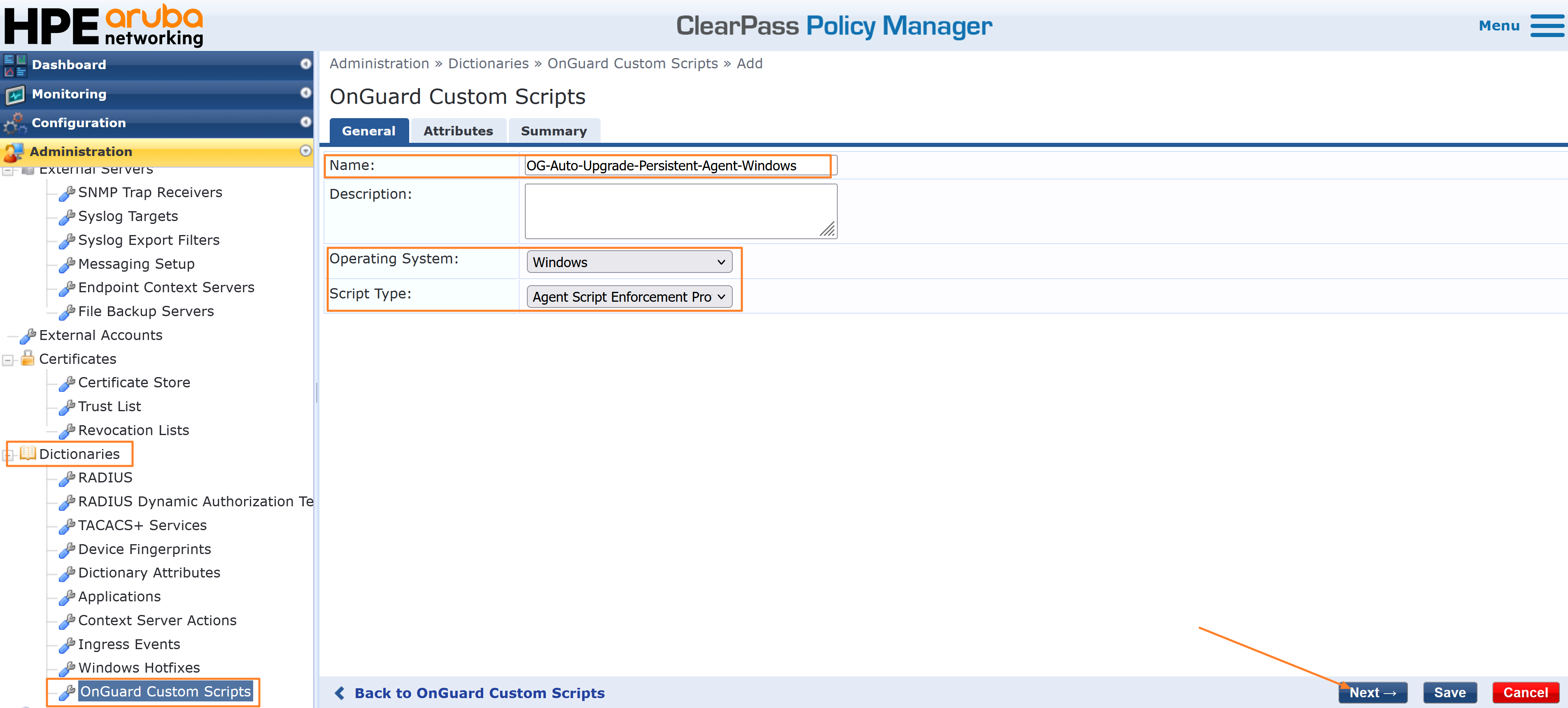
- Set the below attributes with their respective values and click on Save. You can use a SHA checksum calculator tool to determine the SHA-256 checksum for the agent installer and the Download URL can be modified as needed to point to a node in the ClearPass cluster or to an external file server.
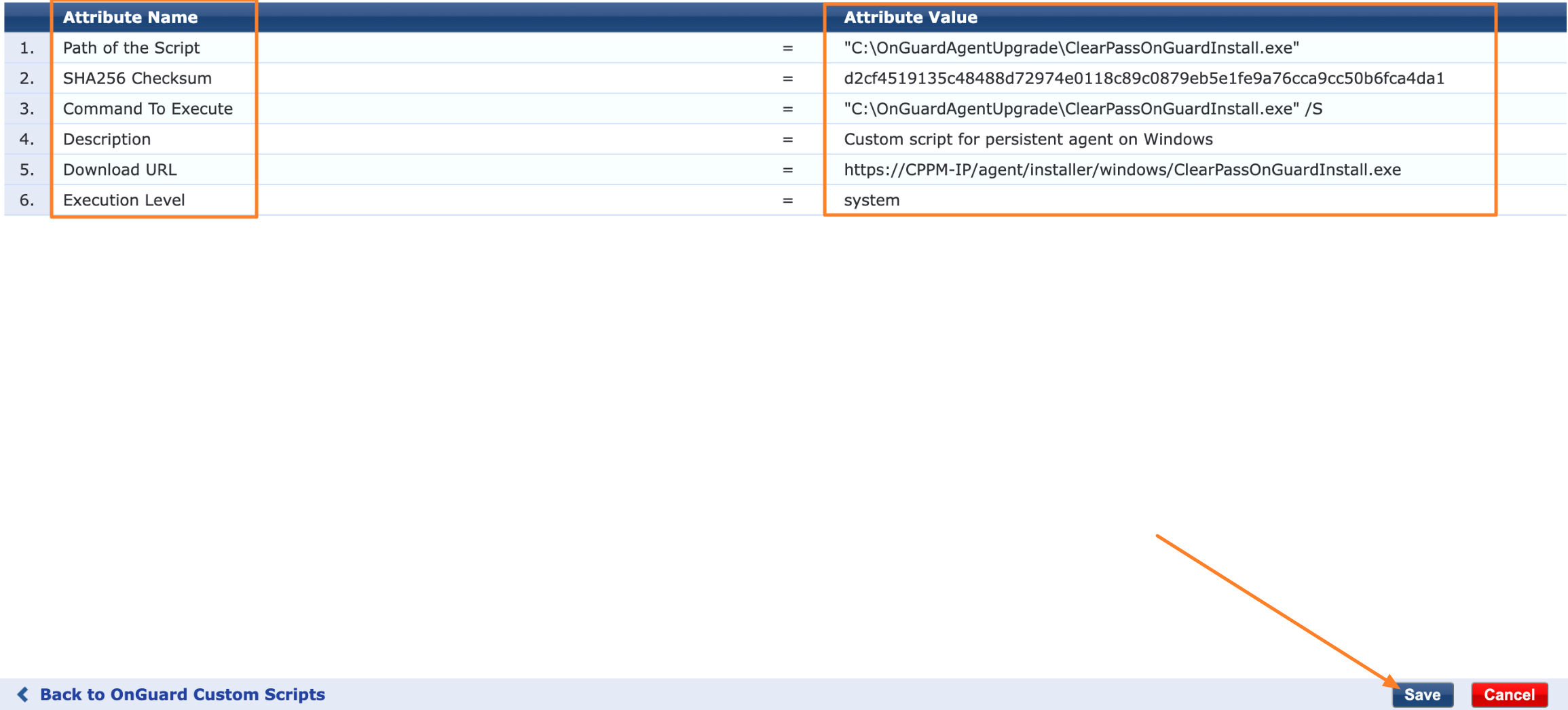
Path of the script: Installer file path on client machine. For example, “C:\OnGuardAgentUpdate\ClearPassOnGuardInstall.exe”
Download URL: Installer URL path on ClearPass or external file server. If you are using ClearPass, The URL can be found under the Installer section of OnGuard Settings.
Execution level: system. The installer requires elevated privileges to install the package on the client machine.
SHA256 Checksum: Checksum of installer file. Use the command below to generate it on Windows.
Get-FileHash ClearPassOnGuardInstall.exe -Algorithm SHA256
Command to Execute: This is the command which would run on the endpoint machine. In this example, this command silently installs the OnGuard agent on the client machine.
C:\OnGuardAgentUpdate\ClearPassOnGuardInstall.exe /S
-
Create an enforcement profile to apply the custom script to OnGuard clients that require an agent upgrade upon authentication with ClearPass. Navigate to Configuration → Enforcement → Profiles → Add to create a new enforcement profile.
-
Select Agent Script Enforcement as the template, provide a profile name, and click Next.
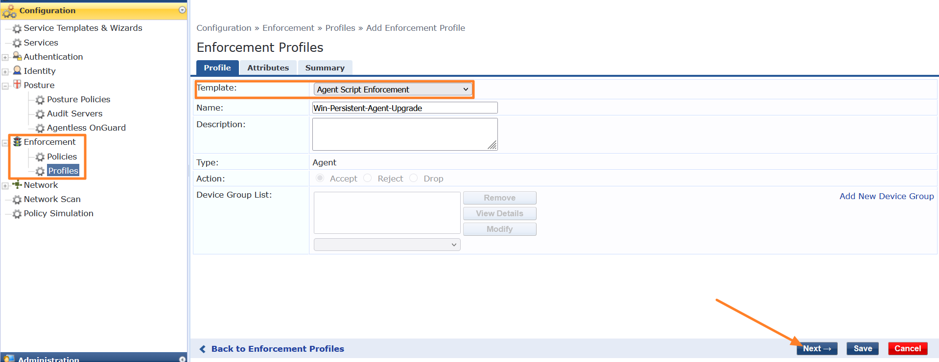
-
Under the Attributes tab, select Custom Script as the Agent Script attribute added to the dictionary in the previous steps, and click Save.
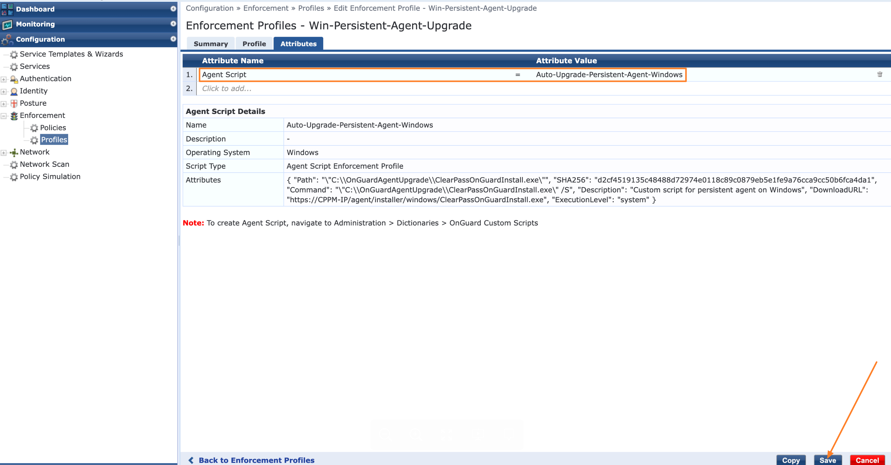
-
The next step is to create an enforcement policy with rules that trigger the enforcement profile upon client authentication with ClearPass. For instance, a rule can be configured to trigger the enforcement profile when the client’s OnGuard Agent version matches 6.11.x. When a client machine that meets this condition authenticates with ClearPass, the enforcement profile is triggered and executes the custom script to download and install the latest OnGuard Agent version on the client machine.
-
To add an enforcement policy, navigate to Configuration → Enforcement → Policies → Add. Provide a name, select WEBAUTH as the enforcement type, and click Next. For the default profile, either create a placeholder profile with no enforcement action or retain the existing value if modifying an existing enforcement policy.
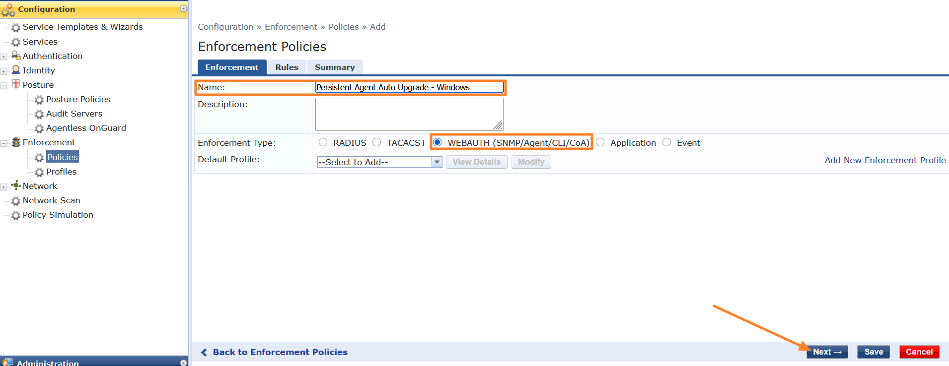
-
Under the Rules tab, add the necessary rules to trigger the enforcement profile containing the custom script. In this example, AgentVersion and OSType are used as conditions. The Host:AgentType attribute is used to match both agent modes — OnGuard as an Agent and OnGuard as a Service — select one or both depending on your deployment settings. Once the conditions are configured, select the enforcement profile with the custom script to be applied when the conditions match. Click Save to complete the enforcement policy configuration.
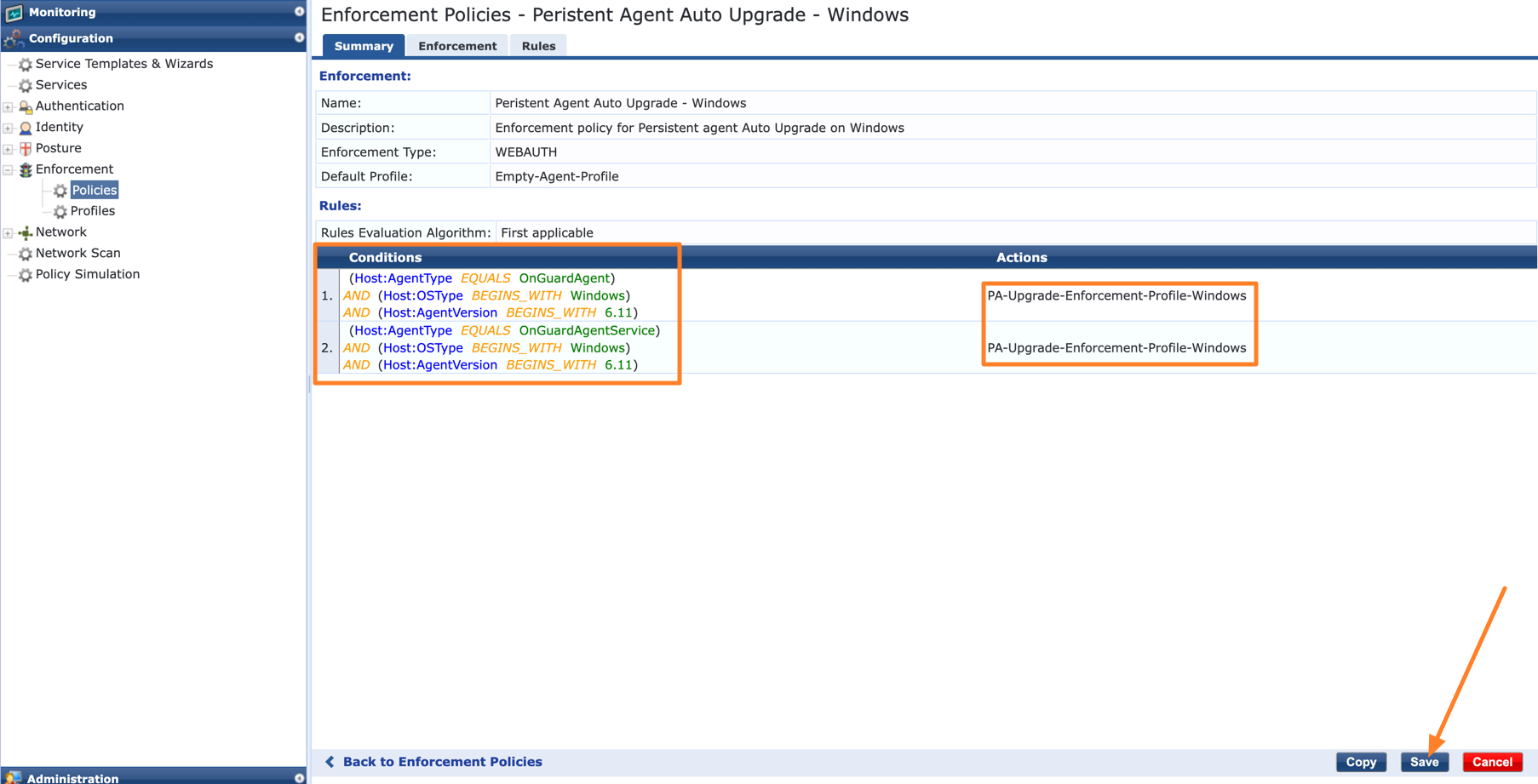
-
The final step is to apply the enforcement policy to the service used for authentication by OnGuard Agents. When a client machine authenticates through that service, the enforcement policy is triggered and, if the conditions match, executes the custom script to download and install the latest OnGuard Agent version on the client machine.
-
Navigate to Configuration → Services and select the target service. If creating a new service, attach the enforcement policy directly. If editing an existing service, update the enforcement policy already mapped to that service by adding the rules, conditions, and enforcement profile containing the custom script for the agent upgrade, as described in the previous steps.
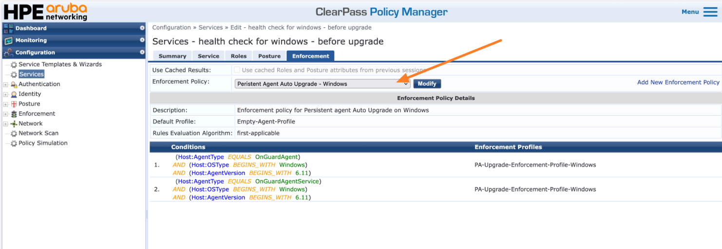
The steps above establish the baseline configuration required for upgrading OnGuard Agents using custom scripts. The following sections outline the modifications needed based on the agent type (Persistent, Agentless, or Dissolvable) and the client operating system.
Agentless OnGuard on Windows
When configuring the Custom Script for Agentless OnGuard, update the following configurations:
Under the General tab, configure the following:
- Operating System: Windows
- Script Type: Agent Script Enforcement Profile
Under the Attributes tab, configure the following:
-
Path of the Script: Installer file path on the client machine. For example,
C:\OnGuardAgentlessUpdate\AgentlessOnGuardWrapper.exe -
Download URL: The URL can be found under the Installer section of OnGuard Settings. For example,
https://<cppm-ip>/agent/AgentlessOnGuard/windows/AgentlessOnGuardWrapper.exe -
Execution Level: system
-
SHA256 Checksum: Checksum of the installer file. The checksum can be found under the Agentless OnGuard section of OnGuard Settings.
-
Command to Execute:
C:\OnGuardAgentlessUpdate\AgentlessOnGuardWrapper.exe
Within the Enforcement Policy, update the following rule condition for Agentless OnGuard on Windows:
- Agent Type: Agentless | OS Type: Windows with operator BEGINS_WITH, mapped to the relevant enforcement profile.
macOS
Persistent Agent on macOS
The following modifications apply to the baseline configuration described above.
Custom Script Changes
When configuring the custom script, apply the following adjustments:
General Tab
- Operating System: macOS
- Script Type: Agent Script Enforcement Profile
Attributes Tab
-
Path of the Script: Installer file path on the client machine. For example,
/var/tmp/OnGuardAgentUpdate/ClearPassOnGuardInstall.dmg -
Download URL: The URL can be found under the Installer section of OnGuard Settings. For example,
https://<cppm-ip>/agent/installer/mac/ClearPassOnGuardInstall.dmg -
Execution Level: system
-
SHA256 Checksum: Checksum of the installer file. Use the following command to generate it on macOS:
shasum -a 256 ClearPassOnGuardInstall.dmg -
Command to Execute: The following command mounts the DMG file and installs the OnGuard Persistent Agent on the client machine:
M=$(hdiutil attach /var/tmp/OnGuardAgentUpdate/ClearPassOnGuardInstall.dmg -nobrowse | awk '/\/Volumes\//{print substr($0,index($0,"/Volumes/"))}' | tail -1); sudo installer -pkg "$(find "$M" -maxdepth 2 -name '*.pkg' -print -quit)" -target / && hdiutil detach "$M"
Enforcement Policy Changes
Under the Rules tab, configure the following conditions:
- Condition 1: Agent Type: OnGuardAgent | OS Type: macOS, mapped to the relevant enforcement profile
- Condition 2: Agent Type: OnGuardAgentService | OS Type: macOS, mapped to the relevant enforcement profile
Agentless OnGuard on macOS
The following modifications apply to the baseline configuration described above.
Custom Script Changes
When configuring the custom script for Agentless OnGuard, apply the following adjustments:
General Tab
- Operating System: macOS
- Script Type: Agent Script Enforcement Profile
Attributes Tab
-
Path of the Script: Installer file path on the client machine. For example,
/var/tmp/OnGuardAgentlessUpdate/AgentlessOnGuardWrapper-mac.tar.gz -
Download URL: The URL can be found under the Installer section of OnGuard Settings. For example,
https://<cppm-ip>/agent/AgentlessOnGuard/mac/AgentlessOnGuardWrapper-mac.tar.gz -
Execution Level: system
-
SHA256 Checksum: Checksum of the installer file. The checksum can be found under the Agentless OnGuard section of OnGuard Settings.
-
Command to Execute: The following command extracts and executes the Agentless OnGuard installer on the client machine:
WP=/var/tmp/OnGuardAgentlessUpdate && tar -zxvf $WP/AgentlessOnGuardWrapper-mac.tar.gz -C $WP && chmod +x $WP/AgentlessOnGuardWrapper && $WP/AgentlessOnGuardWrapper && rm -rf $WP 2>&1
Enforcement Policy Changes
Under the Rules tab, configure the following condition:
- Condition 1: Agent Type: Agentless | OS Type: macOS, mapped to the relevant enforcement profile
Native Dissolvable Agent on macOS
Custom Script Enforcement is not supported for the Native Dissolvable Agent. Manual installation is required for agent upgrades. Follow the steps below:
- Once the user connects to the network, they are redirected to the Guest
web login page.
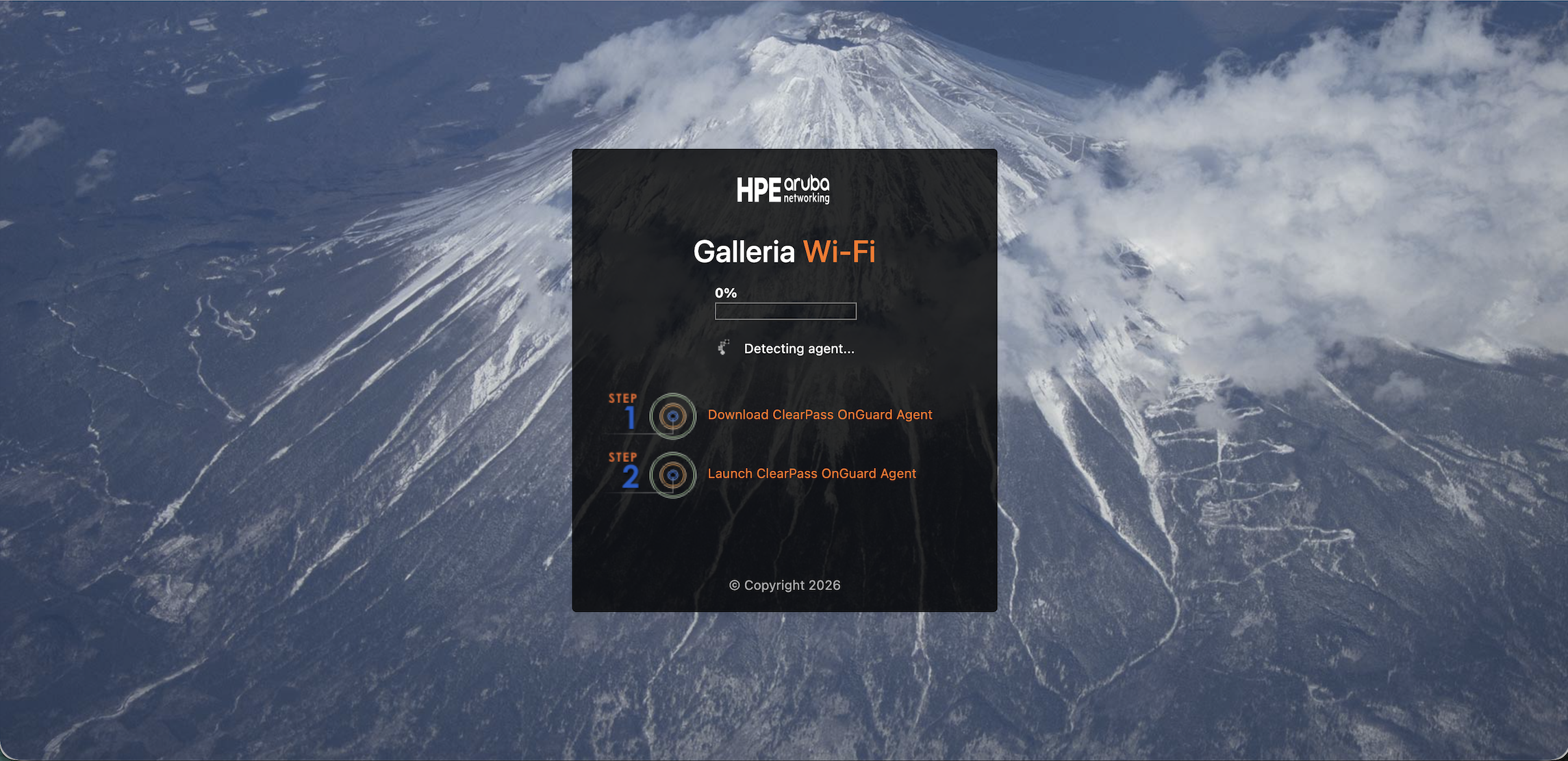
- The Web Agent attempts to upgrade but fails, displaying the following message:
“Installation failed. Please contact your administrator.”
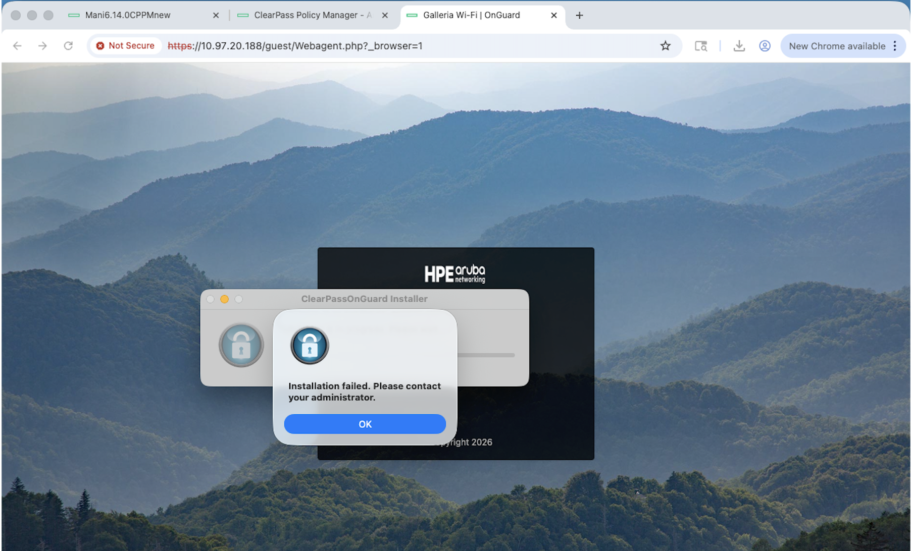
- The Guest web login page remains on:
“Upgrading agent. Please wait…”
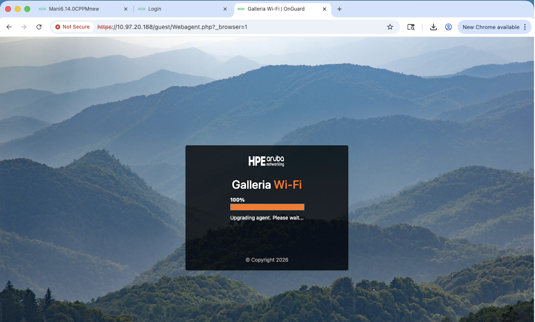
- To upgrade the Web Agent manually, navigate to the login page and download
the agent using the Download ClearPass OnGuard Web Agent Launcher (Mac)
link.

- Once downloaded, install the agent manually to complete the upgrade.
The Download Web Agent link is not displayed by default. One way to make it available to users within the weblogin page is to add the
following custom HTML and script which will provide them download link. If you wish to use this option then go to
Configuration → Pages → Web Logins → Footer HTML to add the custom HTML and script.
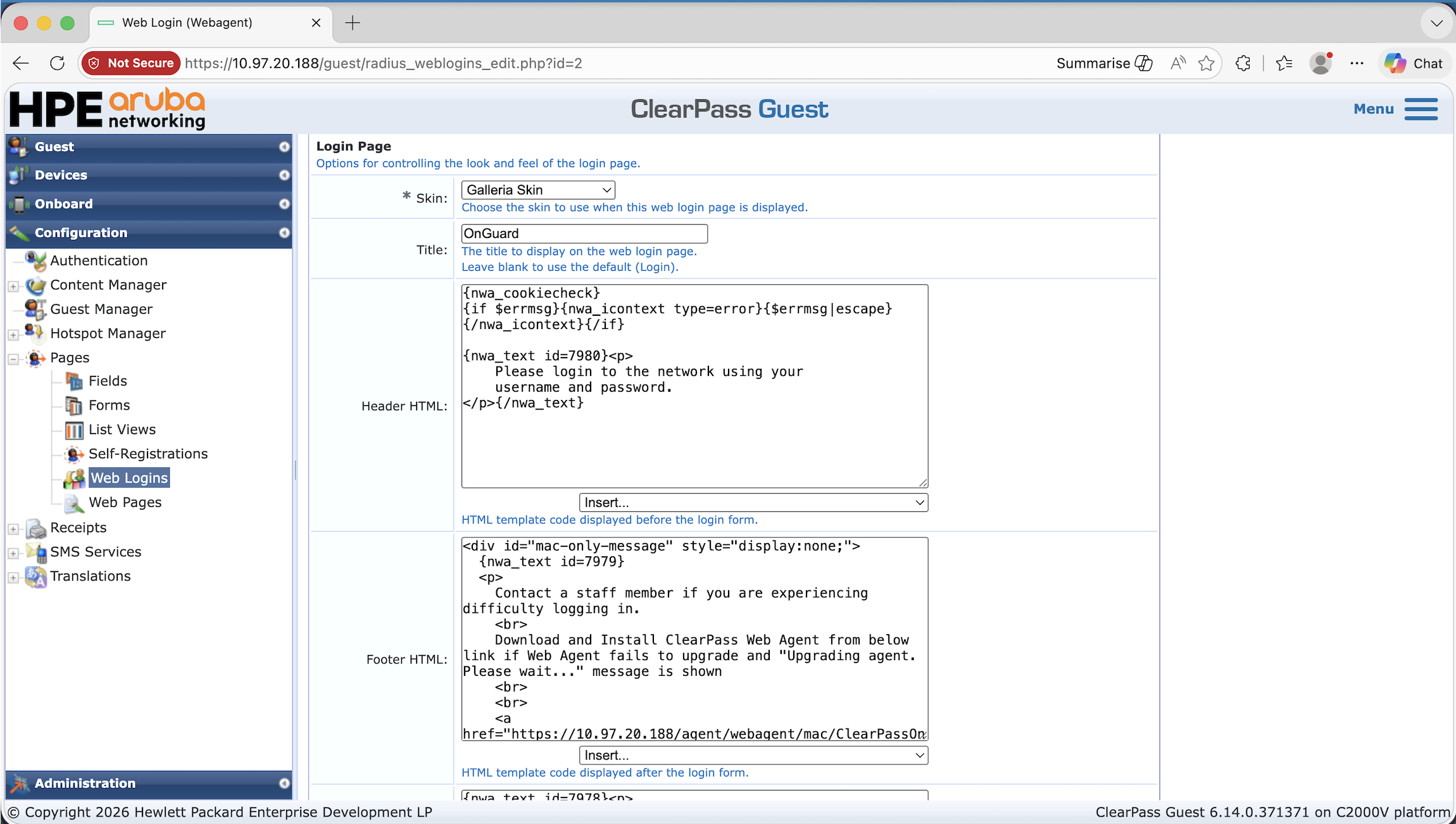
<div id="mac-only-message" style="display:none;">
  {nwa_text id=7979}
  <p>
    Contact a staff member if you are experiencing difficulty logging in.
    <br>
    Download and install the ClearPass Web Agent from the link below if the
    Web Agent fails to upgrade or "Upgrading Agent. Please wait..."
    message is displayed.
    <br><br>
    <a href="https://<cppm-ip>/agent/webagent/mac/ClearPassOnGuardWebAgentLauncher">
      Download ClearPass OnGuard Web Agent Launcher (Mac)
    </a>
    <br>
  </p>
  {/nwa_text}
</div>

{literal}
<script>
(function () {
  var platform = (navigator.userAgentData && navigator.userAgentData.platform)
                 || navigator.platform || "";
  var ua = navigator.userAgent || "";
  var isMac = /Mac/i.test(platform) || /Macintosh|Mac OS X/i.test(ua);

  if (isMac) {
    document.getElementById("mac-only-message").style.display = "block";
  }
})();
</script>
{/literal}
Linux
Persistent Agent on Linux
The following modifications apply to the baseline configuration described above.
Custom Script Changes
When configuring the custom script, apply the following adjustments:
General Tab
- Operating System: Linux
- Script Type: Agent Script Enforcement Profile
Attributes Tab
-
Path of the Script: Installer file path on the client machine. For example,
/var/tmp/onguard-agent-update/ClearPassOnGuardInstall.tar.gz -
Download URL: The URL can be found under the Installer section of OnGuard Settings. For example,
https://<cppm-ip>/agent/installer/ubuntu/ClearPassOnGuardInstall.tar.gz -
Execution Level: system
-
SHA256 Checksum: Checksum of the installer file. Use the following command to generate it on Linux:
shasum -a 256 ClearPassOnGuardInstall.tar.gz -
Command to Execute: The following command extracts and installs the OnGuard Persistent Agent on the client machine:
rm -f /tmp/agent.conf && WP=/var/tmp/onguard-agent-update && tar zxvf $WP/ClearPassOnGuardInstall.tar.gz -C $WP && cd $WP && EXE=$(find $WP -type f -perm -111 | head -n 1) && $EXE --silent --auto-update > /dev/null 2>&1 && rm -rf $WP
Enforcement Policy Changes
Under the Rules tab, configure the following conditions:
- Condition 1: Agent Type: OnGuardAgent | OS Type: Linux, mapped to the relevant enforcement profile
- Condition 2: Agent Type: OnGuardAgentService | OS Type: Linux, mapped to the relevant enforcement profile
Agentless OnGuard on Linux
The following modifications apply to the baseline configuration described above.
Custom Script Changes
When configuring the custom script for Agentless OnGuard, apply the following adjustments:
General Tab
- Operating System: Linux
- Script Type: Agent Script Enforcement Profile
Attributes Tab
-
Path of the Script: Installer file path on the client machine. For example,
/var/tmp/onguard-agentless-update/AgentlessOnGuardWrapper-linux.tar.gz -
Download URL: The URL can be found under the Installer section of OnGuard Settings. For example,
https://<cppm-ip>/agent/AgentlessOnGuard/linux/AgentlessOnGuardWrapper-linux.tar.gz -
Execution Level: system
-
SHA256 Checksum: Checksum of the installer file. The checksum can be found under the Agentless OnGuard section of OnGuard Settings.
-
Command to Execute: The following command extracts and executes the Agentless OnGuard installer on the client machine:
WP=/var/tmp/onguard-agentless-update && tar zxvf $WP/AgentlessOnGuardWrapper-linux.tar.gz -C $WP && EXE=$(find $WP -type f -perm -111 | head -n 1) && $EXE && rm -rf $WP
Enforcement Policy Changes
Under the Rules tab, configure the following condition:
-
Condition 1: Agent Type: Agentless | OS Type: Linux, mapped to the relevant enforcement profile
5 - vMotion with ClearPass
Background
Customers become dependent on solutions and applications to help them run their business. Part of the deployment will typically include planning to ensure that the deployed systems are available and they provide a level of availability in line with the demands of the application and business. For example it’s not as important to plan for the same uptime in an application used to process luncheon-vouchers as that of an enterprise wide identity store providing authentication and authorization for the entire employees of a company, e.g. ClearPass Policy Manager.
Customers plan for availability in multiple ways and generally leverage multiple different hardware and software components. As an example many large enterprise customers will incorporate technology such as multiple Storage Area Networks to consolidate data, for high-availability this may include synchronous or asynchronous replication between them.Typically x86 and x64 environments will have been consolidated onto VMware ESXi. This virtualized technology encompasses multiple features to enable high availability for these virtualized servers. We will discuss the use of vMotion specifically in this Tech Note to assist in providing a layered HA solution.
In the area of availability, CPPM itself utilizes clustering at a software level to provide scale and Availability.
ClearPass High Availability
Multiple CPPM instances can be deployed locally or in a distributed environment to provide scale and to enable High-Availability. We will classify this solution as an active/passive software solution with regard to HA.
In a cluster of CPPM instances a CPPM can be either a Publisher or a Subscriber. Any CPPM instance can process authentications/authorization for clients but a Publisher is required in the cluster as this system is responsible for the configuration of the cluster and for database writes, such as the creation of Guest accounts or the creation of Onboard client certificates. If we lose the Publisher then we can still authenticate users to the network but we are unable to make configuration changes or create new Guest accounts.
In the event of a Publisher failure, CPPM provides for an automatic and a manual solution for this failure, as discussed below.
Manual Solution
A CPPM subscriber instance can be manually promoted to a Publisher via the GUI as shown below. Under Administration > Server Manager > Server Configuration > [select CPPM], then click the Promote to Publisher link, and click Yes to confirm the promotion as shown below.

A CPPM Subscriber can also be manually promoted to a Publisher via the CLI, using the command cluster make-publisher an example is shown below.
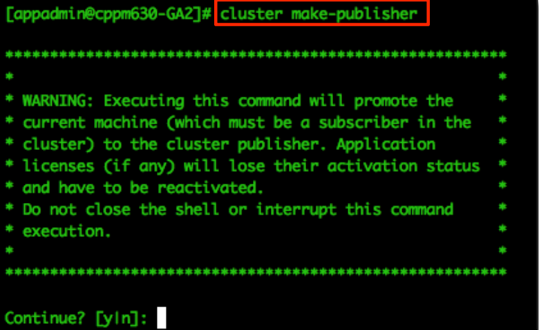
Automatic Solution
CPPM provides for a Subscriber to not only process authentications/authorizations etc. but it can also function in a role as a ‘Standby Publisher’. This provides for the Subscriber to monitoring the health and availability of the active-Publisher, it monitors for the availability of the Publisher DB every 60 seconds. In the event of a failure, i.e. it is not able to connect to the Publishers DB based upon the ‘Failover Wait Time’ it will begin the process of promoting itself to a Publisher. The default Timeout is 10 minutes, with a minimum value of 5 minutes and a maximum of 60 minutes. During this process all the necessary changes to its configuration and databases to allow it to function as a Publisher will be made. Any other Subscribers in the cluster that need to communicate with the Publisher are informed that this system is now the Active-Publisher and it is now responsible for any configuration changes and that they must now replicate changes from this node.
Configuring the automatic fail-over does depend on the fact that the ClearPass servers have previously been configured in a cluster.
Under Administration > Server Manager > Server Configuration > Cluster-Wide Parameters > Standby Publisher > set Enable Publisher Failover to TRUE, and then select the Designated Standby Publisher.

The option to have a CPPM node self-promoting itself to be the Active-Publisher is extremely useful. However there is a delay that could be deemed as too long by some. The time it takes for a system to effectively become the Active-Publisher from the time the Primary-Publisher fails can be as long as 7-8 minutes.
Applications for vMotion
Having discussed at a high-level that we have in our architecture the necessary features to provide for scale and availability in CPPM why would you want to invest in additional hardware/software to enable a more real-time active-active HA solution?
Some Enterprises who offer for example Guest access for Public Venues need to have the ability to constantly create accounts, a failure of 7-8 minutes may not be acceptable. Remember, when creating Guest accounts for users this must be performed on a Publisher.If this has failed or been taken out of service then no new accounts can be created.
Using a solution such as VMware vMotion allows an enterprise to provide an additional level of application availability. For example, if an ESXi host needs to be taken out of service for maintenance or upgrades then the process today to ensure that the availability of a standalone CPPM or the Publisher within a cluster is maintained is not real-time.
VMware vMotion provides the ability to Live Migrate a CPPM VM under load with little (approximately 2-3 seconds) to zero downtime. Most of the delay is dependent on the processing ability of the ESXi host, the amount of Memory in the VM and the underlying network to transport/replicate the memory pages between systems.
Requirements for vMotion
To successfully use vMotion requires a product like vSphere vCenter Server and multiple VMware vSphere Hypervisor (ESXi) hosts. There are many VMware products that include the functionality required to vMotion a VM. Refer to www.vmware.com/products to decide what is right for your environment.
Ensure that hosts that use vMotion are configured to use shared storage. During a migration with vMotion, the migrating VM must be on storage accessible to both the source and target hosts. Shared storage is typically a storage area network (SAN), but can also be implemented using iSCSI and NAS shared storage.
How vMotion works
To say we are moving a VM from one ESXi server to another with vMotion is a bit of a lie, we don’t actually move the data at all, this stays on the shared storage, it’s only the VM’s memory contents that are moved from one ESXi server to another. The VM on the first ESXi server is duplicated on to the second ESXi server and then the original is deleted, during vMotion the first ESXi server creates an initial pre-copy of memory from the running VM into the second ESXi server, during the copy process, a log file is generated to track all changes during the initial copy phase (it is referred to as a memory bitmap). Once the VM’s are practically at the same state, this memory bitmap is transferred to the second ESXi server, before the transfer of the bitmap file the VM on the first ESXi server is put into a quiescent state. This state reduces the amount of activity occurring inside the VM that is being migrated, it allows the bitmap to become so small that it can be transferred very quickly, it also allows for rollback if a network failure occurs, this means that the migration will have to be successful or unsuccessful. When the bitmap has been transferred the users are then switched to the new ESXi server and the original VM is removed from the first ESXi server.
You need the following to perform a vMotion, the below requirements are for both ESXi servers involved
-
Shared storage visibility between the source and destination ESXi servers
-
A VMkernel port group on a vSwitch configured with 1Gbps or faster (10GB ideally)on the vMotion network, it will require a separate IP address.
-
Access to the same network, preferably not going across L3 switches/routers, etc.
-
Consistently labeled vSwitch port groups
-
Compatible CPUs
vMotion Configuration
To configure vMotion on your ESXi hosts there are a few very basic requirements.

You must ensure that vMotion is enabled on your VMkernel management network. If not messages similar to the below will be shown when you try to run a vMotion on a VM.

If you do experience messages similar to the above then configuration changes will be required to the underlying VMware networking interfaces.
Note: We renamed our port to make it a more sensible name/label. We used ‘Mgmt and vMotion’. Click on ‘Properties’ and ensure as shown below that vMotion is enabled on the port on this vSwitch.

If vMotion is not enabled, click ‘Edit’ on the ‘vMotion and IP Storage Port’ and then enable and save as shown on the following screen.

Beyond the basics of configuring the base ESXi system and configuring a standard CPPM VM and ensuring that the vMotion as shown above is configured that is all you need to do.
Using vSphere Web Client to vMotion an active-CPPM VM
There are multiple methods available from within vCenter’s GUI to initiate a vMotion. Below we have shown one option. We have navigated to and we are displaying all the VM’s that are registered and managed by vCenter. Another option would be to view the individual ESXi host and see the VM’s installed on that host as another method.
By right clicking on the VM we have selected (CPPM – Prod VM (10.2.100.225), under ‘All vCenter Actions’ we can see an option to ‘Migrate’ the VM.
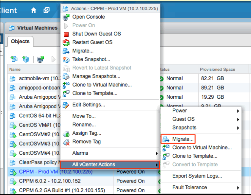
Choose what type of vMotion you want to perform; in our case we will change the hosting ESXi server, the first option.
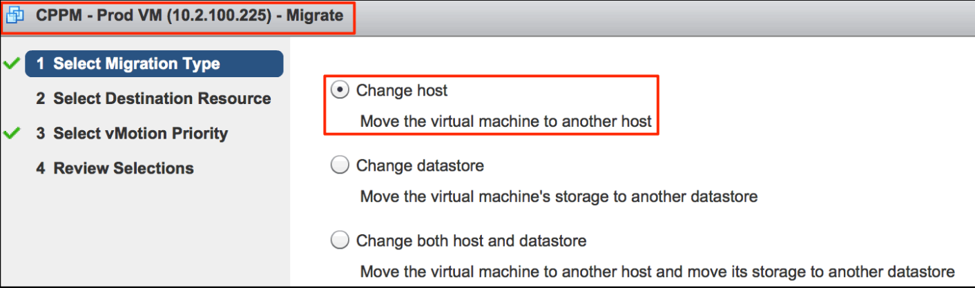
Next select the target ESXi server that will be the destination server for the VM.

Once all your parameters have been selected, confirm and click on the Finish button. vCenter will now move the VM between the source and target ESXi servers.

Monitoring the Move
On the right-hand side of the main vCenter screen you see a visual indication under ‘Recent Tasks’ of the progress of the migration. Once the move is complete a green-tick indicator is displayed as shown below for the previous vMotion we performed. You can see that the current migration is 45% complete and that the previous vMotion completed successfully.

To see additional details about the underlying vMotion process, i.e. the time it took for them to complete you can look under the Monitor then Tasks tab. You can see the start/completion times (2:31:02-2:31:11),to/from ESXi hosts (10.2.100.50-10.2.100.51)
| Related events: | Related events: |
|---|---|
| January 24,2014 at 2:31:11 PM PST January 24,2014 at 2:31:02 PM PST | Migration of virtual machine CPPM-Prod VM (10.2.100.225) from 10.2.100.51, datastore-nas to 10.2,100.50, datastore-nas completed |
| January 24,2014 at 2:31:11 PM PST January 24,2014 at 2:31:02 PM PST | =Migrating CPPM-Prod VM (10.2.100.225) off host 10.2.100.51 in TME-LAB |
| January 24, 2014 at 2:31:02 PM PST | Migrating CPPM -Prod VM (10.2.100.225) from 10.2.100.51, datastore-nas to 10.2.100.50, datastore-nas in TME-LAB |
vMotion Failover Timings
As part of our research we performed multiple timings to understand the expected fail-over performance.
Several factors are directly related to the delay.
• Performance characteristics of the underlying ESXi Server
• Size of the CPPM VM in use
• Workload of the VM – more auth being process = more memory pages changing
• VM-500 (4GB of Memory [default] – minimum recommended size)
• VM-5k (8GB of Memory [default] – minimum recommended size)
• VM-25K (24GB of Memory [default] – minimum recommended size)
• Speed and Utilization of the underlying Network 1GB-Minimum / 10GB-Reccomended
Below is a collection of our timings; we’d expect your performance to be closely inline or better than our findings below. Whilst running the Under-load test we typically did not see any auth failures, we also ran a constant ping to the host with out loss of any packets.
As a rule when ran the vMotion test multiple times. The times below represent what is a $9 5 ^ { t h } +$percentile of the average process time.
| vMotion VM Type (RAM) | 1Gbps Idle | 1Gbps Under load | 10Gbps Idle | 10Gbps Under load |
|---|---|---|---|---|
| VM-500 (4MB) | ~9 seconds | 9 seconds | ||
| VM-5K (8MB) | ~12 seconds | ~14 seconds | ||
| VM-25K (24MB) | ~18 seconds | ~18 seconds |
To expand on the testing we performed. We utilized an in-house testing tool which simulates a number of users performing RADIUS authentication and Guest Users registering through an registration portal, we also ran a constant PING to the VM. Whilst the testing automation was running we performed a vMotion’ed on the active VM, we never experienced a missed PING but did at times experience very minor Guest registration failures. In a live network, the expected user experience is that they might have to re-enter the details into the registration portal again to complete their registration.
Following are copies of our vMotion logs showing the failover times under an idle environment.



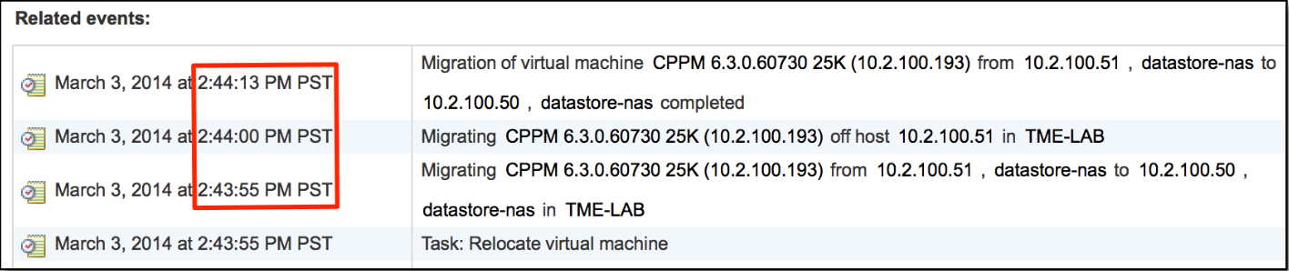
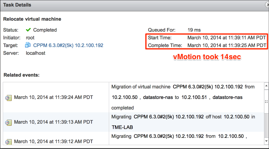
6 - Configuring IPsec tunnels in ClearPass
IPsec Headers
The IPsec protocol defines two headers for authentication and encryption.
Authentication Header (AH)
The Authentication Header authenticates the sender and guarantees the integrity of the message; it does not provide privacy (encryption).

The sender generates a hash of the non-mutable fields in the IP header and the message data. The hash is encrypted with either the sender’s private key for certificate based authentication or the pre-shared key for PSK authentication to generate a digital signature (AH Header).
Encapsulating Security Header (ESP)
The Encapsulating Security Header authenticates the sender, guarantees the integrity of the message and provides privacy by encrypting the message data.

The message data is encrypted by the ESP header, and the ESP Auth Trailer provides the digital signature that authenticates the sender and guarantees the integrity of the data.
Deployment Modes
Site to Site

IPsec gateways encrypt traffic between sites. The IPsec gateways encrypt traffic on behalf of local hosts. In this mode the endpoints of the IPsec connection are the public addresses of the gateways. Local traffic between the host and the IPsec gateway is not encrypted.
Host to Host

In Host to Host mode traffic is encrypted end to end between hosts. The endpoints of the IPsec connection are the IP address of the local hosts.
IPsec Modes
Tunnel Mode
Tunnel mode is most commonly used between gateways, or between an end-station and a gateway, the gateway acts as a proxy for the hosts behind it.

In tunnel mode the ESP Header is placed in front of the original IP Header. The original IP destination and source addresses are encrypted. A new IP header is added to the front of the packet. Typically the new IP addresses are the public addresses of the IPsec gateways. Tunnel mode is typically used for Site to Site deployments.
Transport Mode
In Transport mode the ESP header is placed in front of the massage data. The original IP address of the end stations are exposed.

Transport mode is typically used between end-stations or between an end-station and a gateway where the gateway is being treated as a host. An example might be an encrypted Telnet session from a workstation to a router.
Internet Key Exchange (IKE)
IKE is a protocol that belongs to the IPsec protocols suite. Its responsibility is setting up security associations between two IPsec peers. IKE was introduced in 1998 and was later superseded by version 2 roughly 7 years later.
The primary differences between IKEv1 and IKEv2 are:
-
IKE2 requires fewer messages to establish the Security Association
-
IKEv2 supports EAP authentication as well as pre-shared key and certificate authentication. IKEv1 does not support EAP and can only choose between a pre-shared key and certificate authentication.
-
IKEv2 incorporates NAT traversal. NAT traversal is necessary when a router along the route performs Network Address Translation.
-
IKEv2 includes a check to detect whether the tunnel is still alive or not. If the check fails, IKEv2 will automatically re-establish the connection.
IKEv1 Modes
IKEv1 supports two modes; Main Mode and Aggressive mode. The difference is the number of messages required to establish the Security Association. Main mode requires six packets to establish the SA while Aggressive mode only needs four. Main Mode is considered slightly more secure.
IPsec Algorithms
Key Exchange Algorithms
Diffie-Hellman Key exchange algorithms are used to securely derive a shared secret value between two computers over an unsecured network connection. The computers exchange information that, when processed by the algorithm, produces the shared secret. A third computer listening on the network and intercepting network packets between the first two computers cannot determine the shared secret value. The shared secret value can then be used as a session key, or to generate a session key, to encrypt the rest of the communications used in the IPsec negotiations. Higher group numbers offer increased security but require additional time / computes to derive the shared secret,
Diffie-Hellman Groups
-
1 – Group 1 768 bit group Note: Group 1 is no longer considered secure
-
2 – 1024 bit group
-
5 – 1536 bit group
-
14 – 2048 bit group
-
19 – 256 bit elliptical curve group
-
20 – 384 bit elliptical curve group
Data Integrity Algorithms
Data integrity algorithms ensure that a packet received from a remote computer was not modified in transit. The sending computer calculates a hash value from the data payload of the network packet. This hash is then cryptographically signed and attached to the packet. The receiving computer performs the same calculation on the data payload of the packet and compares it to the hash that was attached by the sender. If the hashes match, then the data has not been modified. If the hash values do not match, then the packet was altered between the source and the destination and the receiving computer drops the packet. Data integrity algorithms do not encrypt the data; encryption protocols must be used for that purpose. Some Integrity Algorithms include:
-
HMAC-SHA
-
HMAC-SHA256
-
HMA-SHA384
-
HMAC-MD5
IKE2 supports the Pseudo Random Function (PRF) variant of the Integrity Algorithms. The HMAC variants support a truncated output while the PRF variant does not.
-
PRF-HMAC-SHA
-
PRF-HMAC-SHA256
-
PRF-HMA-SHA384
-
PRF-HMAC-MD5
Privacy Algorithms
Symmetric Privacy algorithms are used to encrypt message data. The symmetric keys are derived from the Diffie-Hellman Key Exchange algorithms. Longer keys are more secure and require more compute power for encryption and decryption.
-
3DES
-
AES128
-
AES192
-
AES256
ClearPass Configuration
ClearPass supports IPsec connections on both the Management and Data interfaces. Typically the connections are between ClearPass nodes or between ClearPass and controllers or switches.
ClearPass to ClearPass
Typical deployments include providing additional security for nodes in a local ClearPass cluster, between a local ClearPass node and a ClearPass node in the DMZ, or between a local ClearPass node and a ClearPass node at a remote site.

To configure the IPsec tunnel select Administration » Server Manager » Server Configuration – Network
Select Create IPsec Tunnel

The Create IPsec Tunnel screen configures the local Management or Data interface.

The IPsec Mode, IKE Version, IKEv1 Phase 1 mode and Authentication type are not negotiated between the IPsec peers and must match for the local and remote endpoints. If the authentication algorithms and encryption algorithms do not match they can be negotiated between the peers. To be sure the desired algorithms are chosen select the same ones for each peer.
Select the Local and remote IP address for the IPsec peers and select Tunnel or Transport mode.

Since this is a host to host deployment there are no IPsec gateways. If tunnel mode is selected the new IP header (unprotected) will be the same as the IP header (encrypted).
Next select the IKE parameters and Authentication Type

If IKE version 1 is selected choose the phase 1 mode; Main or Aggressive mode. Main mode is more secure but requires more bandwidth. If IKE version 2 is selected there are no phase 1 options.
There are two options for Authentication type; Pre-Shared Key and Certificate

Pre-Shared keys are simpler to configure but are generally considered less secure. The Pre-Shared key (IKE Shared Secret) is used for creating a digital signature (encrypting the authentication hash). The receiver uses the same key to decrypt the hash and if they match the peer is authenticated. Certificate based authentication is similar. The two peers exchange x509 certificates. The certificates contain the peer’s public keys and must be signed by a certificate authority the receiver trusts. The sender encrypts the authentication hash with its private key and the receiver authenticates by decrypting the hash with the public key from the sender’s certificate. Pre-Shared Keys and certificates are not used to encrypt message data
IKE uses Diffie-Hellman key exchange to derive a shared secret for the IPsec peers. The Diffie-Hellman Group selected should reflect the sensitivity of the information being encrypted. Higher group numbers are more secure. Groups 19 and 20 are Suite-B elliptical curve algorithms.
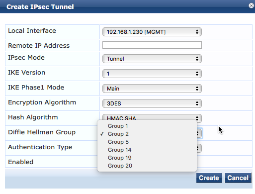
INFO
Group 1 is no longer considered secure and should not be used
If IKE version 1 has been selected the authentication algorithms available are;
Non FIPS Mode FIPS Mode
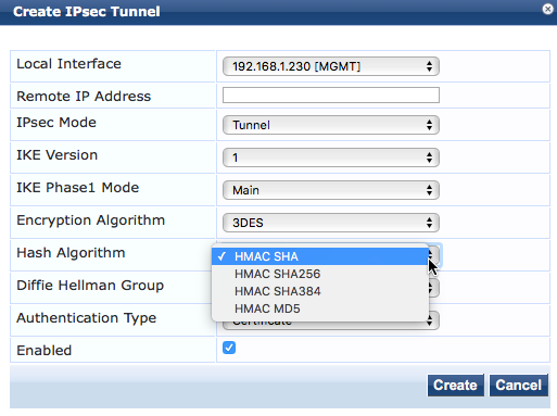
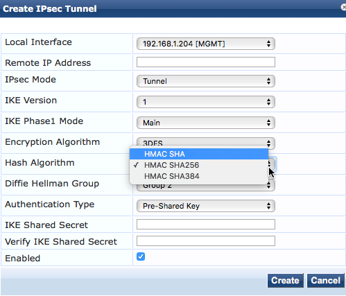
If IKE version 2 was selected the PRF variants are used
Non FIPS Mode FIPS Mode
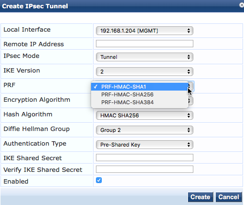
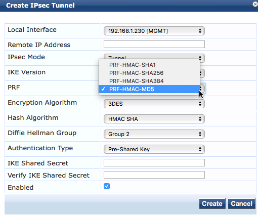
MD5 has been shown to have collision weaknesses; different inputs may produce the same output. This may make it unsuitable for authentication hashing. MD5 hashing is disabled in FIPS mode.
The encryption algorithms available are;

Longer key lengths are more secure but require more compute power to encrypt and decrypt the data. AES (Advanced Encryption Standard) 256 provides the highest level of protection.
Pre-Shared Key Authentication Example
Configure both of the IPsec peers

Once the Security Association is negotiated and the connection established the status can be viewed by clicking on the Action icon

If the connection does not come up

It may be necessary to stop and restart the IP Service on both peers

Certificate Based Authentication Example
In certificate based authentication the IPsec peers exchange X509 certificates during the IKE protocol SA negotiation. The certificate contains the Pubic key of the IPsec peer and must be issued (signed) by a certificate authority the receiving peer trusts. The issuing certificate authority must be in the receiving peer’s “Trust List”
The HTTPS server certificate is used for IPsec connections.

Since the default CPPM server certificate is self signed it will not be trusted by the other IPsec peer. In this example we will use publicly signed certificates.

Configure the IPsec peers
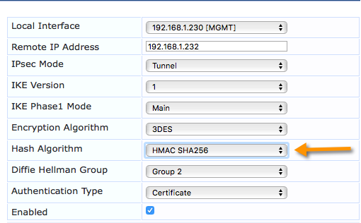
INFO
The Hash Algorithm must match the Signature Algorithm in the Certificate.

Verify that the IPsec connection is established

If certificates issued by a Public Certificate Authority are not available the Onboard CA can be used to issue the certificates.
In Onboard create a new Certificate Authority

Make sure the Digest Algorithm is supported by the IPsec peers
After the CA is created select edit Certificate Authority

Select a Digest Algorithm that the IPsec Peers support.
After the new CA is configured correctly generate a Certificate Signing Request (CSR) on each of the IPsec Peers.

Upload the Certificate Signing Requests to the Certificate Authority.


Select Certificate Type: Trusted Certificate and Issue certificate immediately.
From the Manage Certificate screen select certificate type: Trusted and Export the Certificates for the IPsec peers

These will be uploaded as the HTTPS certificate for each Peer.
Next select Certificate type: Certificate Authority and export the Root and Intermediate (signing) certificates

These will be added to the trust list on each Peer.
Configure the IPsec peers for certificate based authentication

ClearPass to Aruba Controller
The following configuration will establish an IPsec tunnel between the Aruba Controller and the ClearPass Server. Since IPsec is Layer-3, this will work whether the two devices are on the same network or different networks, so long as the networks between the two devices allow IPsec.

Preshared Keys
ClearPass Configuration

Aruba Controller Configuration
The following procedure will describe how to setup the Controller-side of the IPsec tunnel.
-
Log in to the Aruba Controller and go to ‘Configuration > Advanced Services – VPN Services’ and go to the ‘Site-to-Site’ tab
-
Under ‘IPsec Maps’, click ‘Add’
-
Fill in the appropriate information to meet the IPsec settings required. The image below shows both a PSK-based IKEv1 AES256, as well as a PSK-based IKEv2 AES256 IPsec tunnel on the controller. Note that for IKEv2, the destination subnet mask is different than for IKEv1. This may be corrected in a later version of AOS.
-
Once done, click the ‘Done’ button, and then ‘Apply’ at the bottom of the page, and then save the configuration.


ClearPass IPsec Troubleshooting
INFO
For IKEv2, to address a transport-mode issue, the destination subnet mask on the controller for a single host needs to be set at 255.255.255.254’ to work properly. This may be corrected in a later version of AOS.
Verify IPsec Connection – Controller
Log in to the controller’s CLI and run the following commands:
-
Show crypto isakmp sa
-
Show crypto ipsec sa

Troubleshooting
ClearPass
There are three primary logs that provide valuable troubleshooting information
-
PolicyManagerLogs 🡪 Platform-ipsec
-
SystemLogs 🡪 ipsec-conn.txt
-
SystemLogs 🡪 Var 🡪 Log 🡪 messages
Ipsec-conn.txt
This file shows the IPsec Security Associations
Listening IP addresses:
192.168.1.204
Connections:
ipsec-3025: 192.168.1.204…192.168.1.205 IKEv1, dpddelay=30s
ipsec-3025: local: [OU=Domain Control Validated, CN=cp.dpblab.net] uses public key authentication
ipsec-3025: cert: “OU=Domain Control Validated, CN=cp.dpblab.net”
ipsec-3025: remote: uses public key authentication
ipsec-3025: child: dynamic === dynamic TUNNEL, dpdaction=restart
Security Associations (1 up, 0 connecting):
ipsec-3025[5]: ESTABLISHED 54 minutes ago, 192.168.1.204[OU=Domain Control Validated, CN=cp.dpblab.net]…192.168.1.205[OU=Domain Control Validated, CN=cp1.dpblab.net]
It also shows the Certificate used for the connection. In this example the certificate for cp.dpblab.net was issued by the public CA godaddy
List of X.509 End Entity Certificates:
altNames: cp.dpblab.net, www.cp.dpblab.net
subject: “OU=Domain Control Validated, CN=cp.dpblab.net”
issuer: “C=US, ST=Arizona, L=Scottsdale, O=GoDaddy.com, Inc., OU=http://certs.godaddy.com/repository/, CN=Go Daddy Secure Certificate Authority - G2”
serial: e6:a3:7f:bb:ce:4b:1d:68
validity: not before Mar 19 15:38:38 2015, ok
not after Dec 13 11:38:03 2015, ok (expires in 23 hours)
pubkey: RSA 2048 bits, has private key
keyid: 96:2f:67:06:7d:49:9e:15:6a:69:92:f4:b0:e2:3d:34:cd:6b:73:09
subjkey: ef:ca:0f:73:46:14:a5:f6:c9:c5:ab:f2:ce:04:d6:2c:3f:6d:a6:16
authkey: 40:c2:bd:27:8e:cc:34:83:30:a2:33:d7:fb:6c:b3:f0:b4:2c:80:ce
altNames: cp1.dpblab.net, www.cp1.dpblab.net
subject: “OU=Domain Control Validated, CN=cp1.dpblab.net”
issuer: “C=US, ST=Arizona, L=Scottsdale, O=GoDaddy.com, Inc., OU=http://certs.godaddy.com/repository/, CN=Go Daddy Secure Certificate Authority - G2”
serial: ba:a7:70:4d:8e:22:32:cd
validity: not before Oct 08 16:10:38 2015, ok
not after Oct 08 16:10:38 2016, ok
pubkey: RSA 2048 bits
keyid: aa:03:69:ea:a7:bd:c0:84:cb:e0:ac:15:da:75:df:ba:77:a5:99:68
subjkey: d7:26:a0:11:8d:90:88:ac:ec:66:cd:c7:02:2a:6c:c9:be:99:16:70
authkey: 40:c2:bd:27:8e:cc:34:83:30:a2:33:d7:fb:6c:b3:f0:b4:2c:80:ce
The next section is a list of Trusted certificate Authorities; this is from the ClearPass trust list. The CA that signed the IPsec Peers certificate must be in the trust list
List of X.509 CA Certificates:
subject: “C=US, ST=Arizona, L=Scottsdale, O=GoDaddy.com, Inc., OU=http://certs.godaddy.com/repository/, CN=Go Daddy Secure Certificate Authority - G2”
issuer: “C=US, ST=Arizona, L=Scottsdale, O=GoDaddy.com, Inc., CN=Go Daddy Root Certificate Authority - G2”
serial: 07
validity: not before May 03 03:00:00 2011, ok
not after May 03 03:00:00 2031, ok
pubkey: RSA 2048 bits
keyid: b4:55:50:14:83:45:1f:ee:8c:a0:a1:0c:f5:af:de:3a:4c:5e:11:59
subjkey: 40:c2:bd:27:8e:cc:34:83:30:a2:33:d7:fb:6c:b3:f0:b4:2c:80:ce
authkey: 3a:9a:85:07:10:67:28:b6:ef:f6:bd:05:41:6e:20:c1:94:da:0f:de
subject: “C=US, ST=Arizona, L=Scottsdale, O=GoDaddy.com, Inc., CN=Go Daddy Root Certificate Authority - G2”
issuer: “C=US, O=The Go Daddy Group, Inc., OU=Go Daddy Class 2 Certification Authority”
serial: 1b:e7:15
validity: not before Jan 01 02:00:00 2014, ok
not after May 30 03:00:00 2031, ok
pubkey: RSA 2048 bits
keyid: 21:0f:2c:89:f7:c4:cd:5d:1b:82:5e:38:d6:c6:59:3b:a6:93:75:ae
subjkey: 3a:9a:85:07:10:67:28:b6:ef:f6:bd:05:41:6e:20:c1:94:da:0f:de
authkey: d2:c4:b0:d2:91:d4:4c:11:71:b3:61:cb:3d:a1:fe:dd:a8:6a:d4:e3
subject: “C=US, O=The Go Daddy Group, Inc., OU=Go Daddy Class 2 Certification Authority”
issuer: “C=US, O=The Go Daddy Group, Inc., OU=Go Daddy Class 2 Certification Authority”
serial: 00
validity: not before Jun 29 13:06:20 2004, ok
not after Jun 29 13:06:20 2034, ok
pubkey: RSA 2048 bits
keyid: ee:e5:9f:1e:2a:a5:44:c3:cb:25:43:a6:9a:5b:d4:6a:25:bc:bb:8e
subjkey: d2:c4:b0:d2:91:d4:4c:11:71:b3:61:cb:3d:a1:fe:dd:a8:6a:d4:e3
authkey: d2:c4:b0:d2:91:d4:4c:11:71:b3:61:cb:3d:a1:fe:dd:a8:6a:d4:e3
subject: “C=US, ST=California, L=Sunnyvale, O=Aruba Networks, CN=ClearPass Onboard Local Certificate Authority (Signing), E=dab@labnet.com”
issuer: “C=US, ST=California, L=Sunnyvale, O=Aruba Networks, CN=ClearPass Onboard Local Certificate Authority, E=dab@labnet.com”
serial: 0f
validity: not before Oct 13 11:32:54 2015, ok
not after Oct 13 12:02:54 2025, ok
pubkey: RSA 2048 bits
keyid: 69:4d:73:f1:6a:ec:2e:f5:a8:6d:e5:51:08:eb:d8:92:f2:de:14:ac
subjkey: 5d:39:61:4f:eb:3d:18:7d:21:9d:33:2c:53:0b:1b:cc:f6:06:20:8d
authkey: b5:42:f6:ed:db:d5:1f:c0:3a:c3:7f:b0:7d:09:c8:42:46:c4:b4:7d
Platform-ipsec
ipsec-3024[3] to 192.168.1.205
no private key found for ‘CN=cp.dpblab.net’
configuration uses unsupported authentication
tried to check-in and delete nonexisting IKE_SA
establishing connection ‘ipsec-3024’ failed
This shows a mismatch between the authentication algorithm negotiated by the IPsec peers and the authentication (signing) algorithm contained in the certificate
Messages
Dec 12 08:53:10 cp charon: 08[IKE] initiating Main Mode IKE_SA ipsec-3024[2] to 192.168.1.205
Dec 12 08:53:10 cp charon: 08[IKE] IKE_SA ipsec-3024[2] state change: CREATED => CONNECTING
Dec 12 08:53:10 cp charon: 08[IKE] no private key found for ‘CN=cp.dpblab.net’
Dec 12 08:53:10 cp charon: 08[CFG] configuration uses unsupported authentication
Dec 12 08:53:10 cp charon: 08[MGR] tried to check-in and delete nonexisting IKE_SA
This shows a mismatch between the authentication algorithm negotiated by the IPsec peers and the authentication (signing) algorithm contained in the certificate
Dec 10 10:07:29 cp charon: 01[CFG] selected proposal: IKE:AES_CBC_192/HMAC_SHA1_96/PRF_HMAC_SHA1/MODP_1024
Dec 10 10:07:29 cp charon: 01[IKE] reinitiating already active tasks
Dec 10 10:07:29 cp charon: 01[IKE] ISAKMP_VENDOR task
Dec 10 10:07:29 cp charon: 01[IKE] MAIN_MODE task
Dec 10 10:07:29 cp charon: 01[ENC] generating ID_PROT request 0 [ KE No NAT-D NAT-D ]
Dec 10 10:07:29 cp charon: 01[NET] sending packet: from 192.168.1.204[500] to 192.168.1.205[500] (244 bytes)
Dec 10 10:07:29 cp charon: 14[NET] received packet: from 192.168.1.205[500] to 192.168.1.204[500] (244 bytes)
Dec 10 10:07:29 cp charon: 14[ENC] parsed ID_PROT response 0 [ KE No NAT-D NAT-D ]
Dec 10 10:07:29 cp charon: 14[IKE] reinitiating already active tasks
Dec 10 10:07:29 cp charon: 14[IKE] ISAKMP_VENDOR task
Dec 10 10:07:29 cp charon: 14[IKE] MAIN_MODE task
Dec 10 10:07:29 cp charon: 14[ENC] generating ID_PROT request 0 [ ID HASH ]
Dec 10 10:07:29 cp charon: 14[NET] sending packet: from 192.168.1.204[500] to 192.168.1.205[500] (76 bytes)
Dec 10 10:07:29 cp charon: 12[NET] received packet: from 192.168.1.205[500] to 192.168.1.204[500] (76 bytes)
Dec 10 10:07:29 cp charon: 12[ENC] parsed ID_PROT response 0 [ ID HASH ]
Dec 10 10:07:29 cp charon: 12[IKE] IKE_SA ipsec-3022[1] established between 192.168.1.204[192.168.1.204]…192.168.1.205[192.168.1.205]
Dec 10 10:07:29 cp charon: 12[IKE] IKE_SA ipsec-3022[1] state change: CONNECTING => ESTABLISHED
This shows a successful connection
Controller
Turn on debugging
config t
logging level debug security process l2tp
logging level debug security process crypto
logging level debug security subcat vpn
logging level debug security subcat IKE
Show Security Log
Then, while it is connecting, do a “show log security 50”
Jan 22 13:37:50 :103063: <DBUG> |ike| 192.168.1.206:500-> ike_phase_1_send_KE_NONCE 192.168.1.206
Jan 22 13:37:50 :103063: <DBUG> |ike| GetFirstMatchIsakmpPSK: entering
Jan 22 13:37:50 :103063: <DBUG> |ike| mask FFFFFFFF, ip C0A801CE, key_ip C0A801CE
Jan 22 13:37:50 :103060: <DBUG> |ike| ike_auth.c:ike_auth_get_key:603 Found isakmp policy for peer 192.168.1.206 client:no
Jan 22 13:37:50 :103063: <DBUG> |ike| ike_phase_1_post_exchange_KE_NONCE IV len:16
Jan 22 13:37:50 :103063: <DBUG> |ike| ike_phase_1_post_exchange_KE_NONCE done 192.168.1.206 g_x_len:128 skeyid_len:20
Jan 22 13:37:50 :103063: <DBUG> |ike| 192.168.1.206:500-> message_parse_payloads: invalid next payload type <Unknown 113> in payload of type 5
Jan 22 13:37:50 :103060: <DBUG> |ike| 192.168.1.206:500-> message.c:message_drop:2886 Message drop from 192.168.1.206 port 500 due to notification type INVALID_PAYLOAD_TYPE
Jan 22 13:37:50 :103053: <INFO> |ike| Drop message from 192.168.1.206 due to invalid IKE shared-secret
Jan 22 13:37:54 :103063: <DBUG> |ike| 192.168.1.206:500-> message_parse_payloads: invalid next payload type <Unknown 113> in payload of type 5
Jan 22 13:37:54 :103060: <DBUG> |ike| 192.168.1.206:500-> message.c:message_drop:2886 Message drop from 192.168.1.206 port 500 due to notification type INVALID_PAYLOAD_TYPE
Jan 22 13:37:54 :103053: <INFO> |ike| Drop message from 192.168.1.206 due to invalid IKE shared-secret
In this example the Peers shared secret does not match
7 - Updating after License Transfer
Customers who purchased ClearPass Policy Manager prior to 2019 likely will likely see their licenses in HPE Networking Support Portal https://networkingsupport.hpe.com/ as both ClearPass NL and ClearPass Legacy. When they upgraded to ClearPass 6.7 (or later) their licenses followed the conversion process outline in the ClearPass 6.7 License Conversion TechNote https://www.hpe.com/psnow/doc/a00108259en_us As the original purchased appliances reached the End of Support Life (EoSL) milestone they were provided the option to continue to maintain those licenses and transfer them to be independent of the original purchase through the ClearPass Access license transfer process.
When customers purchase one of the associated nine (9) transfer SKUs they are then able to continue to use those converted legacy licenses going forward. This document helps identify the steps required by the customer to correctly update their information in HPE Networking Support Portal to ensure that they do not have service disruptions with functionality or support.
Note that HPE is unable to automatically perform this task in many cases due to the legacy behavior that allowed customers to use the same Subscription ID in multiple ClearPass servers. To ensure that the proper licenses are correctly mapped, this does require customers to validate their records for accuracy.
Upon completing the to acquire transfer licenses, the customer should receive an Email with the electronic software delivery receipt information. An example of this from a customer purchasing the R9R50AAE part would look like the one shown below.

Because the transfer SKU does not issue a new license activation key, the resulting page will only indicate a new License Serian Number (LSN) for the purchase.

This License Serial Number should then be used to re-map the existing licenses that are desired to be used in HPE Networking Support Portal.
Prior to continuing, the customer is recommended to execute the “show license” command on their ClearPass Policy Manager systems that contain Access NL licenses. This is typically the publisher node only.
This will result in an output similar to the following taken from an evaluation system
[appadmin@clearpass1]# show license
Application : Access
License key : —–BEGIN ACCESS LICENSE KEY—–
H4sIAAAAAAACAwAAAv/9A22uXvNDg0MP9RIsoLWdKFv1zeRVqjD25ni/scMwh9VFwMjSuSb4rPo6
J3auJ6XOu8j0c9qBBGVZsr6WcJMnJMEu6cYluKmhWYv8fId1lEzjSb/Td0IPMzl/ryCBgBCOKLQr
mwaaBwC1NAzOEMT+SJ+j6SRLLhaQlvWYajY+ejrfhYSA0Sq90huNG3vPeEE/ZfcQPLTm3MJ57oCn
wiEOypk1hKgcHGh5NGad4X6+sIW1HafbJ2FhtZrCPt5KzxGlSN+GhC7Uj/HftD9vygxbLi3ZnJEc hLk90wDuF/x2+0Hy2cbDh4nRN210dLGacgth2yrMa6xIftqkyGbCSSFGoDRK3ZLq/WTsrYByOZ4r
yeWKaUhDJ+5gyRrupKmoelm641x4PFLCLOIpdvHlSvZokhjmqnt2K6fsc7uO62wgzjb2gjJ6rOT+
mJN2sCuHYidKVEmQhRR7ZvZdkI6CxWyYMVoeNN8CsTZn51PSZNurf++VQeoMUy/WDgZQVZt68p//
Wq/+DDDdsUBHlPLWHlDAUyKBAPAEhe/EEVOy+IjlVGYr9MF7JIgTKLcm+KRYulm/vxPfMT1JONTz
+GrXMAfhUSahHsfFXH/MkxBxUWf8shH+K3Prpb3eFONvA+U5fZ9+Y5AthIQcxFxlA7ACCaref1zT
lZxKsE42OJ5h6qJ8G+AAAAD//w==
—–END ACCESS LICENSE KEY—–
License key type : Permanent
License added on : 2024-03-04 07:34:47
Validity : <not applicable>
Issued for : 100 users
License Support End Date : 2024-09-04 07:34:53
Customer id : XNZE42XN
Licensed features : <not applicable>
Application : ClearPassPlatform
License key : —–BEGIN CLEARPASS PLATFORM LICENSE KEY—–
H4sIAAAAAAACAwAAAv/9nfG4hN7uG+VT032RrF6H0yULFFuAg+VqLXdKh8iwPuGM+V2BkQM6+GWE
rRSx4bCYHuz8YBGABz76lsEorHrzqmlDbqBgVshbj0KndgK7N01pBU+UAZfxcedHeI6ijPtWyRUV
AZb6iOsnXxnTspPAkUngI2ZbeXsRZENQ5a2g/f3726kJVxV92qZf51nmsD2v7pkQeze4AwYFZ1FN
kgzw54sr1F44D416SwyHyeFVCd7SpJuMNizcKZ/80SP2z5F/Yo0JmRqjhLrIKEP6YUMQuxAQLSUX
7Pw/nkD4y+zs+I4dH4XIjrsIuhEB0CpzrQooxDv5juiZJrek5G1LQ+bpHTpO0AyFu0ys48sLKLHf
7mzAaPgcCleSHaIbSYGZIb9QYcggnEUnwgfYd5uiGyA9ER4NwwMcmEs0eTh9xx4xZD6vBQnZq3HJ
yLR5xDUMUJMrjqvca2OGxfpnK3NDSC3LoqhVPZop3bbE+78bNvllKa+Gsqs3BcBXl782NXfyMfQt
/LtmBPV9oJGJrKxK+MIGDCi7/xF7HbK6IowbWl1x9asec1VgLQKrC8WH1vD/jh7ami/OfkFZJuVE
p3+D+gVSS2jhbYOP7klDJjstQgVrdgpCY3Zn6Ct+IuiNMD4lVkh6zfZ7nJrAeUaLpCANizOnSpP3
4Holh4+O6wIBa8/hG5MAAAD//w==
—–END CLEARPASS PLATFORM LICENSE KEY—–
License key type : Permanent
License added on : 2024-03-03 13:29:25
Validity : <not applicable>
License Support End Date : 2024-09-03 13:42:55
Customer id : XNZE42XN
Licensed features : <not applicable>
=======================================================
[appadmin@ clearpass1]#
Open HPE Networking Support Portal and select the License Management System option.

Within the License Management section, select “ClearPass NL”. If the licenses are already known to be matched up correctly this next step may be skipped.
Select the icon to export the list full list of licenses in Excel format in the upper left corner of the table

Use the exported file to then match the licenses in use to the listed license. This is easiest to accomplish through using only a portion of the license output. For example, to search for the above Access NL license it would be fastest to search only for the string “H4sIAAAAAAACAwAAAv/9A22uXvNDg0MP9RIs” (a portion of the top line of the full license). If more than one license is identified, extend the search string to the complete line and repeat. At this point, note the existing License Serial # value that is listed in the Excel file (also seen in the Licenses list).
At this point customers may select the “Replace LSN” button on the right side of the screen.

When the button is clicked, a new window will appear requesting the following information: Source Serial Number, New Serial Number, and SKU

Using the existing License Serial Number (the one currently displayed in the portal) that matches the Activation Key selected, enter the original (old) License Serial Number. The New Serial Number will be the one obtained in the Software Notification Message Receipt previously.
The SKU is a drop down list that provides the nine (9) available options to select from: R9R49AAE, R9R50AAE, R9R51AAE, S0V37AAE, S0V38AAE, S0V38AAE, S0V40AAE, S0V41AAE, or S0V42AAE. When completed, select the “Replace” button to complete the process. Repeat as required for all transferred licenses.
The process will then change the content from the initial state (before):

To then reflect the updated state (after):

This will then ensure that the proper License Serial Number is matched to the actual license in use.
8 - ClearPass MFA Workflows
Multi Factor Authentication (MFA) is a security mechanism that requires users to present two or more verification factors when accessing a network resource (VPN, Wi-Fi, wired network access, login portals, admin consoles, etc.). It goes beyond traditional username/password authentication to reduce the risk of unauthorized access. Password are inherently insecure with people using the same password in multiple places, choosing weak and easily guessed words, and is highly susceptible to social engineering attacks. MFA provides mitigation from brute force attacks, phishing, and exposed login credentials. MFA is also increasingly becoming part of compliance requirements as well.
While MFA does provide more security than just password, it can also lead to poor user experience if not implemented correctly. Certain workflows are more tolerant of the delays when the user has to access a registered device to respond to the MFA prompt.
The different factors that are used to verify identity and authorize access to network or applications are:
Something you know
- Password
- PIN
- Security Question
Something you have
- TOTP (Time based One Time Password) with mobile authenticator apps (Google Authenticator, Microsoft Authenticator, Okta Verify, Duo Mobile, etc.)
- Push notification approval
- Hardware tokens (Yubikey, RSA Secure ID, Smartcards/CAC),FIDO2 / WebAuthn security keys, HOTP, etc.)
- SMS one time passcode
- Email one time passcode
- Device certificates
Something you are
- Fingerprint (TouchID, biometrics readers)
- Facial Recognition (Windows Hello, Face ID)
MFA workflows with ClearPass
With respect to ClearPass implementation, the following workflows are MFA friendly and commonly deployed:
Management login to ClearPass using SAML SSO
ClearPass supports using SAML SSO for logging into different management interfaces like ClearPass Policy Manager admin UI, Insight module and Guest module. This is standard web based authentication and MFA can be embedded into the login flow itself. Identity providers like Google, Okta, and Microsoft Entra all support adding MFA to web-based login workflows.
Operator login to ClearPass Guest
User can log into ClearPass Guest with different personas to create or manage guest accounts, create or manage device registrations, and approve guest accounts as a sponsor. Operator logins can also be enabled with SAML SSO which can be secured with MFA workflows supported by the IDP.
Management login to other applications and network devices
ClearPass can also act as IDP where the credentials are validated against authentication sources like active directory, Okta, Google workspace etc. This allows using ClearPass for logging into web interface of applications like HPE GreenLake and network elements like firewalls, load balancers, cloud management portals, etc. This is useful when you want to leverage a local identity source like Active Directory or LDAP without having to configure SAML on those identity sources.
TACACS+/RADIUS authentication for management login to network devices
Logging into devices whether its the command line interface or the web can also be secured by using MFA. Typically the authentication protocols used are either RADIUS or TACACS+. ClearPass enables MFA for device logins by either making API calls against the MFA provider or by forwarding the auth request to a RADIUS agent. For example, Okta has a RADIUS agent for triggering MFA. Okta RADIUS agent uses API calls to Okta to authenticate the user and evaluate MFA; either by triggering a push notification or evaluating the MFA token within the password attribute. Below is the flow diagram of how the integration with Okta works:

More details about this integration with Okta can be found at:
https://arubanetworking.hpe.com/techdocs/NAC/tech-corner/okta-mfa/
The integration with PingID uses a direct API integration using the PingID extension in ClearPass. Details about this integration can be found at:
Web login using SAML SSO / Cloud Identity
ClearPass allows captive portal login using SAML SSO and also uses OAuth to authenticate users against a list of cloud identity providers. This is useful when employees need to connect to guest network to maybe onboard their device or to perform some recovery or remediation action. The SAML SSO can be combined with different web based MFA to verify the identity of the user. Cloud identity providers also support a wide range of MFA options.
VPN authentication
RADIUS is typically used for VPN authentication and it can be secured by adding MFA in the form of push notification, FIDO2/WebAuthn, OTP, etc. The primary authentication would validate the user credentials and then a range of MFA options like TOTP, Push, Okta Verify, etc. can be used to further secure the VPN authentication. Note that while CHAP / MS-CHAPv2 can be used for primary authentication, it cannot be combined with MFA since the server needs the password in cleartext to trigger MFA.
802.1X authentication
The most common way to implement MFA with 802.1X is using EAP-GTC protocol. It supports MFA factors like push / TOTP, passcode, RSA tokens, Yubikey OTP but does not support interactive MFA factors like WebAuthn/FIDO2 or security questions. The default supplicants on common OS platforms do not support EAP-GTC natively and hence need a custom supplicant which adds to the complexity of the deployment.
INFO
It is generally not recommended to use MFA for 802.1X authentication on a wireless network. This is due to the user having to go through MFA every time the device gets disconnected from the wireless. 802.1X supplicants are also sensitive to overall time taken for authentication and hence adding extra factors to the authentication flow could result in increase in timeouts depending upon the level of interaction needed from the end user.
Another way to approach securing 802.1X authentication is to use EAP-TLS for authentication and use MFA during the device provisioning or onboarding process so that user identity is verified at the time of the certificate provisioning. Alternatively, it is also possible to use a captive portal after 802.1X to force a web based MFA. However the latter approach leads to a sub optimal user experience and is not generally used outside of environments that have very stringent and specific security requirements.
MFA Providers and ClearPass
ClearPass can integrate with MFA providers in different ways:
- RADIUS proxy: Many MFA providers have a RADIUS interface which can be used to trigger MFA. ClearPass in this case would just proxy the authentication request to the RADIUS interface of the MFA provider. The MFA solution would then handle the secondary factor validation like push notification, OTP validation etc. This requires that the user credentials are in cleartext so supported authentication methods are PAP, EAP-TTLS, and EAP-GTC.
There are different ways in ClearPass to proxy requests to an external RADIUS server like:
- Proxy Target Server used with RADIUS Proxy service type
- Authentication Source of type RADIUS / RadSec
- Token Server Authentication Source
Of these methods, the token server authentication source is best suited for MFA use cases since it allows doing an authorization lookup before sending the request to the MFA provider. This means ClearPass can validate that the user exists in identity source and is a valid user before triggering MFA thus preventing the MFA provider from being overwhelmed by invalid requests.
Popular MFA providers that have a RADIUS interface:
- Okta through Okta RADIUS Agent
- Ping ID through Ping Federate RADIUS Proxy
- Cisco Duo through Duo Authentication Proxy
- Microsoft / Entra ID through NPS
- RSA Secure ID
-
API integration: ClearPass extensions provide ability to integrate with third party applications. At present, there is an extension for PingID that allows ClearPass to use API calls to trigger push notification instead of using the RADIUS interface. The modular and flexible design of extensions allow the development of similar integrations with other provider if needed.
-
HTTP Authorization: The HTTP authentication source in ClearPass can be used to trigger REST API calls against external systems like MFA providers. Most of the providers have REST APIs which can be used to trigger MFA workflows. A HTTP authorization workflow can be used to craft a REST API call to MFA provider which results in a 200 OK response if the validation is successful. Note that each provider has different set of REST APIs and processes to trigger MFA which will not be covered in this document. Please refer to vendor API documentation for more information.
Popular MFA providers that have REST API to trigger push notifications are:
- Okta
- Ping ID
- Cisco Duo
- OneLogin
INFO
Microsoft Graph APIs do not support triggering MFA using API calls so the only way to work with Microsoft Entra for MFA is to proxy the request to a NPS server and have the NPS extension interface with Entra to validate the secondary factors.
https://learn.microsoft.com/en-us/entra/identity/authentication/howto-mfa-nps-extension
ClearPass MFA Matrix
Note that this table lists some MFA providers which are known to work but this is not a comprehensive list. The RADIUS based MFA options can be used with any MFA provider that has a RADIUS interface and the HTTP / API based MFA options can be used with any provider that has REST APIs to trigger MFA.
Most MFA / Identity providers support SAML and OAuth based workflows so that should work with any of the third party providers
