AOS-8 Campus to AOS-10 Tunnel: Configuration and Staging
This guide covers the creation of all HPE Aruba Networking Central configuration objects required to support the reference customer, OWL’s Barcelona_1 site’s AOS-8 campus mode to AOS-10 tunnel mode migration, prior to moving any production devices. It will be configured with the use of two greenfield pilot Mobility Gateways and one access point. The goal is to ensure that Central is fully configured and validated so that device onboarding during the Production Cutover phase produces a predictable, tested result.
Table of contents
All configuration in this guide is derived directly from the discovery outputs and design decisions documented in the Discovery chapter. The following documented settings are authoritative inputs for every subsequent step that follows:
- Device inventory
- WLAN and Other System Configuration
- AOS-8 Mobility Conductor Hierarchy and Configuration Commit Locations
- Central Hierarchy Design
About This Chapter
This guide follows steps defined by the HPE Aruba Networking Central AOS-10 wireless deployment guide.
Configuration will consist of Central configuration element profiles created in the Library and assigned to the scopes required to migrate OWL’s Barcelona_1 site.
The final outcome of this guide is a Central environment that includes the profiles, gateway cluster, authentication servers, and WLAN objects necessary to support three tunneled SSIDs:
- CorpNet (802.1X/Enterprise)
- OpsNet (PSK/Personal)
- GuestNet (Enhanced Open/Central NAC Captive Portal)
Audience
This guide is written for network engineers responsible for staging the Central configuration in advance of an AOS-8 to AOS-10 site migration. Readers are expected to be familiar with:
- HPE Aruba Networking Central navigation and profile management
- Central’s new configuration scope model (Global, Site Collections, Sites, Device Groups, Devices)
- The discovery outputs produced in the preceding Discovery phase
Prerequisites
The following conditions must be satisfied before beginning any configuration steps in this guide.
Design and Discovery
- The Discovery and Design phase is complete, and all discovery deliverables have been reviewed and approved.
- The Central hierarchy, including the Barcelona_HQ site collection, Barcelona_1 site, and all relevant device groups, has been defined and approved.
Network Reachability
- APs and mobility gateways must be able to reach Central. Refer to the Domain Names and Supported Protocols page of the new Central guide for details.
- RADIUS servers at
172.16.23.43and172.16.23.44are reachable from the gateway management network (VLAN 23,172.16.23.0/24). - The default gateway at
172.16.23.1is reachable from the management VLAN. - NTP servers are reachable.
Administrative Access
- Administrator access to HPE Aruba Networking Central
- GreenLake administrator permissions
- Certificate management permissions (if using custom certificates)
System Requirements
- Controllers running 8.10.0.12, 8.12.0.1, or later before upgrading to AOS-10. More details can be found in the Controller-based APs section of the AOS-10 guide
- Gateways upgraded to AOS 10.7 or later
- Internet access for gateways and APs
- Pilot Devices are onboarded and have valid Central subscriptions assigned in GreenLake
Reference Pilot Device Inventory
The following devices will be deployed in this chapter to enable and test configuration of new Central prior to the first production site cutover.
| Hostname | Serial Number | MAC Address | Role |
|---|---|---|---|
| HQ-BAR1-GW01 | MCAXD9FDC | 00:0c:11:9d:9f:e6 | Mobility Gateway |
| HQ-BAR1-GW02 | MCLD2F3B0 | 00:0c:11:02:f3:ba | Mobility Gateway |
| HQ-BAR1-AP01 | VNLBK9T8PQ | d0:d3:aa:c0:8d:a8 | Campus AP |
How to Use This Guide
This chapter is split into four parts plus a command reference. The parts must be completed in order, because objects created in earlier parts are referenced by objects created in later parts. Most notably, the gateway cluster created in Part 3 is a required input to all three WLAN profiles in Part 4, and the VLAN, named VLAN, and authentication server group objects must exist before WLAN profile creation can be completed. Skipping or reordering steps will result in unresolvable dependencies at profile creation time.
Each part ends with exit criteria that confirm the objects created are correctly assigned and visible at the expected scope before proceeding to the next part. Use the Back and Next links at the bottom of each page to move through the sequence.
| Part | Page | Phases | Produces |
|---|---|---|---|
| 1 | Pre-Onboarding: Scopes and Base Profiles | 1 and 2 | Site collections, sites, and device groups as empty containers, plus the pre-onboard profiles a device receives on first contact with Central: NTP, DNS, AP system, VLAN, and named VLAN |
| 2 | Device Onboarding | 3 | Gateways and APs onboarded, placed in a device group and a site, with reverse-translated local profiles (including Gateway System) reviewed |
| 3 | Gateway Cluster and Infrastructure Profiles | 4 | The post-onboard profiles that require a device to exist: user administration, gateway cluster with CoA and VRRP, SNMP, RF, and the RADIUS server and server group profiles |
| 4 | WLAN Profiles | 5 | The CorpNet, OpsNet, and GuestNet WLAN profiles, including the GuestNet Central NAC captive portal |
| Reference | Migration Command Reference | All | AOS-8 and AOS-10 verification commands and device-level Central paths for every profile in this chapter |
Configuration Sequence
Central configuration for a tunnel mode WLAN is not a single list of settings. It is one ordered sequence with two preparation tracks that must be complete before the sequence can reach device provisioning. Visualizing a sequence before reading the individual procedures is the fastest way to build an accurate mental model of what a Central tunnel mode WLAN deployment actually involves.
Preparation tracks
These two top hardware onboarding tracks run in parallel with the early configuration phases and are entirely independent of Central profile work. Both must be complete before Provision Devices in Central can begin.
| Track | Covers | Blocks |
|---|---|---|
| Acquire hardware and software | Gateways and access points are on site, cabled, and running a supported AOS-10 version | Device provisioning |
| Onboard to HPE GreenLake | Gateways and access points are in the device inventory with Central subscriptions and the Central application assigned | Device provisioning |
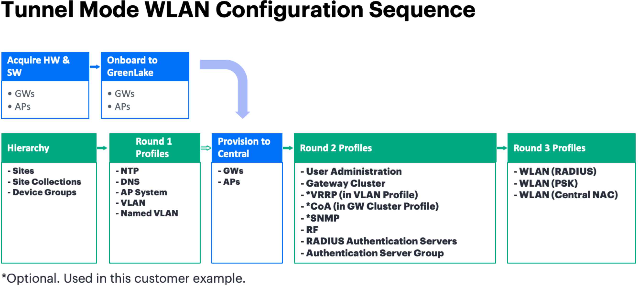
Main sequence
| Phase | Section | Produces |
|---|---|---|
| 1 | Configure Hierarchy Scopes | Site collections, sites, and device groups as empty containers |
| 2 | Configure Profiles - Round 1 | The pre-onboard profiles a device must receive on first contact with Central: NTP, DNS, AP system, VLAN, and named VLAN |
| 3 | Provision Devices in Central | Gateways and APs onboarded, placed in a device group and a site, with reverse-translated local profiles reviewed |
| 4 | Configure Profiles - Round 2 | The post-onboard infrastructure profiles that require a device to exist: gateway cluster, user administration, SNMP, RF, and RADIUS authentication |
| 5 | Configure Profiles - Round 3 | The WLAN profiles themselves, which consume everything built in phases 2 and 4. |
Why the order is what it is
Three dependencies drive the entire sequence and are worth stating plainly before the procedures begin:
- A device cannot be provisioned into Central until a device group and a site exist to hold it, which is why hierarchy comes first.
- A gateway cluster profile can only list gateways that Central already sees in its device inventory, which is why device provisioning has to precede Round 2.
- A tunnel mode WLAN profile requires a gateway cluster, a named VLAN, a user role, and an authentication server group to all exist and be scoped before the WLAN creation wizard can be completed, which is why WLAN profiles are last.
Note: Round 1, Round 2, and Round 3 are not Central features. They are a documentation convention used in this chapter to group profiles by when they can be created relative to device onboarding. Round 1 profiles are created before any device is onboarded, Round 2 profiles require an onboarded device, and Round 3 profiles require the objects built in Rounds 1 and 2.
Key Values
The following OWL values are used throughout the four parts of this chapter. Keep this table open in a separate tab while working through the parts.
| Item | OWL Value |
|---|---|
| Site collection | Barcelona_HQ |
| Site | Barcelona_1 |
| Gateway device group | OWL_GW_BAR1 |
| AP device groups (WLAN and RF assignments) | OWL_HD_APs, OWL_UHD_APs |
| Pilot gateways (management IP) | HQ-BAR1-GW01 (172.16.23.31), HQ-BAR1-GW02 (172.16.23.32) |
| Management VLAN and default gateway | VLAN 23 (OWL-VLAN-23-MGMT / OWL-MGMT), 172.16.23.1 |
| Client named VLANs | OWL-EMPLOYEE (2), OWL-EMPLOYEE_OPS (3), OWL-GUEST (100), OWL-IOT (192) |
| NTP and DNS profiles | OWL-BAR-NTP, OWL-BAR-DNS (10.10.10.10, 10.10.10.11) |
| Gateway cluster | OWL-BAR1-GW_CLUSTER, VRRP VIPs 172.16.23.33 and 172.16.23.34 |
| RADIUS servers and server group | OWL-BAR-RADIUS-01 (172.16.23.43), OWL-BAR-RADIUS-02 (172.16.23.44), OWL-BAR-RADIUS-SVG |
| WLAN profiles | CorpNet-BAR1, OpsNet-BAR1, GuestNet-BAR1 |
Exit Criteria
The Configuration and Staging phase is complete when the following conditions are met:
- The checkpoints and exit criteria on all four part pages are confirmed.
- The gateway cluster is formed, both members are connected, and Dynamic Authorization is enabled with a working VRRP VLAN.
- All three WLAN profiles are visible in the Library, set to Tunnel forwarding mode, and assigned to the correct AP device groups.
- A real client has connected to each SSID and received the expected role and VLAN, and CoA has been demonstrated on a live session where it is a project requirement.
- Every staged profile has been verified at the device level on each pilot gateway and AP, using the Migration Command Reference where needed.
- No unresolved configuration conflicts or missing profile assignments exist in the Central audit trail.
Summary
This phase built the complete target configuration in new Central before any production traffic moves. The hierarchy scopes are in place, the shared profiles are defined once in the Library and assigned at the right scope, the pilot gateways are onboarded with their local overrides reconciled, the gateway cluster is formed with Dynamic Authorization, and all three WLANs are tunneled to the cluster and validated with real clients.
Because the configuration is already staged and verified, the production cutover becomes primarily a device conversion exercise rather than a configuration exercise. That shortens maintenance windows and limits the number of variables in play if something needs to be rolled back. Keep the Migration Command Reference handy during cutover, since the same commands and device-level paths apply when validating each production gateway and AP.
Once the exit criteria are satisfied, proceed to Production Cutover, where the remaining production gateways complete onboarding, production APs are converted and validated against the staged profiles, and production traffic is migrated.