This is the multi-page printable view of this section. Click here to print.
HPE Aruba Networking
- 1: AOS 10
- 1.1: Components
- 1.1.1: Overview
- 1.2: Design fundamentals and concepts
- 1.2.1: Access point deployments
- 1.2.2: Gateway deployments
- 1.2.3: Gateway serviceability
- 1.2.4: Clusters
- 1.2.4.1: Clusters
- 1.2.4.2: Types of clusters
- 1.2.4.3: Cluster roles
- 1.2.4.4: Automatic and manual modes
- 1.2.4.5: Cluster formation process
- 1.2.4.6: Cluster features
- 1.2.4.7: Dynamic authorization in a cluster
- 1.2.4.8: Cluster failover
- 1.2.4.9: Planning a gateway cluster
- 1.2.5: Forwarding modes of operation
- 1.2.6: Access point port usage
- 1.2.7: User VLANs
- 1.2.8: Roles
- 1.2.8.1: Fundamentals
- 1.2.8.2: Management and configuration
- 1.2.8.3: Bridge forwarding
- 1.2.8.4: Tunnel forwarding
- 1.2.8.5: User-Based Tunneling
- 1.2.9: Broadcast and multicast optimization
- 1.2.9.1: Broadcast and multicast optimization
- 1.2.9.2: Transmit data rates
- 1.2.9.3: Broadcast filtering
- 1.2.9.4: ARP unicast conversion
- 1.2.9.5: Router advertisement unicast conversion
- 1.2.9.6: Multicast transmission optimization
- 1.2.9.7: Dynamic multicast optimization
- 1.2.9.8: AirGroup
- 1.2.9.9: Broadcast multicast optimization
- 1.3: Migrating to AOS 10
- 1.3.1: Migrating to AOS 10
- 1.3.2: Preparing Central for AOS 10 migration
- 1.3.3: Access Points
- 1.3.3.1: Configuration retained or migrated
- 1.3.3.2: Migrating Aruba Central managed Instant APs to AOS 10
- 1.3.3.3: Migrating locally managed Instant APs to AOS 10
- 1.3.3.4: Migrating AirWave managed Instant APs to AOS 10
- 1.3.3.5: Migrating controller managed APs to AOS 10
- 1.3.4: Upgrading mobility controllers to gateways
- 1.3.5: FAQ - migrating to AOS 10
- 1.4: Services
- 1.4.1: AirGroup
- 1.4.1.1: AirGroup
- 1.4.1.2: Architecture of the AirGroup technology
- 1.4.1.3: Configuration of AirGroup for an AOS 10 environment
- 1.4.1.4: Personal AirGroup
- 1.4.1.5: Survivability
- 1.4.2: Roaming and the key management service
- 1.4.3: IoT operations
- 1.4.4: Tunnel orchestrator
- 1.4.5: Live upgrade
- 1.4.6: RAPIDS
- 1.4.7: AirMatch
- 1.4.8: ClientMatch
- 1.5: Survivability
- 2: Wi-Fi design and deployment
- 2.1: Wi-Fi design guides
- 2.1.1: Warehouse
- 2.1.2: Large public venue
- 2.1.2.1: Large public venue
- 2.1.2.2: Network design fundamentals and criteria for large public venues
- 2.1.2.3: Radio frequency planning and channel optimization
- 2.1.2.4: Bandwidth planning and capacity calculations
- 2.1.2.5: Security practices and network protection for LPV
- 2.1.2.6: LPV calculator instructions
- 2.2: Wi-Fi generations
- 2.2.1: Wi-Fi generations
- 2.2.2: Wi-Fi 6
- 2.2.3: Wi-Fi 6E
- 2.2.3.1: Wi-Fi 6E
- 2.2.3.2: Features and benefits
- 2.2.3.3: Planning and deployment
- 2.2.4: Wi-Fi 7
- 2.2.4.1: Wi-Fi 7
- 2.2.4.2: Features and benefits
- 2.2.4.3: Planning and deployment
- 2.3: Wi-Fi security
- 2.3.1: Security modes
- 2.3.1.1: Security modes
- 2.3.1.2: WPA3-Enterprise
- 2.3.1.3: WPA3-Personal
- 2.3.1.4: Enhanced Open
- 2.3.1.5: Troubleshooting
- 2.3.2: Security features
- 2.3.2.1: Protected management frames
- 2.3.3: Wireless Intrusion Detection & Protection
- 2.3.3.1: Wireless Intrusion Detection & Protection
- 2.3.3.2: Use cases
- 2.3.3.3: RF scanning methods
- 2.3.3.4: Detection
- 2.3.3.4.1: Detection
- 2.3.3.4.2: Infrastructure event detection levels and signature descriptions
- 2.3.3.4.3: Client event detection levels and signature descriptions
- 2.3.3.5: Classification
- 2.3.3.6: Protection
- 2.3.3.7: Configuring, Monitoring and Reporting WIDS
- 2.3.4: Client authentication options and operations
- 2.3.4.1: RADIUS accounting
- 2.4: Network operations
- 2.4.1: DHCP for APs
- 2.4.1.1: DHCP for APs
- 2.4.1.2: Option implementation
- 2.4.1.2.1: Option implementation
- 2.4.1.2.2: AOS-10
- 2.4.1.2.3: AOS-8 unified
- 2.4.1.2.4: AOS-8 campus
- 2.4.1.2.5: AOS-8 instant
- 2.4.1.3: Server configuration
- 2.4.1.4: Reference
- 3: Location services
- 3.1: Central location services deployment guide
- 3.1.1: Overview
- 3.1.2: Wi-Fi analytics solutions
- 3.1.3: Architecture
- 3.1.4: Design and deployment considerations
- 3.1.5: Partner integration
- 3.1.6: Troubleshooting
- 3.2: Open Locate deployment guide
- 3.2.1: Overview
- 3.2.2: Getting started
- 3.2.3: AP testing and verification
- 3.2.4: Partner integration
- 3.2.5: FAQ
- 4: Private 5G
- 4.1: Solution
- 4.1.1: Overview
- 4.1.2: Components
- 4.1.3: Design
1 - AOS 10
1.1 - Components
1.1.1 - Overview
An introduction to AOS 10 components covering deployment environments, hardware, software, licensing, and personas.
HPE GreenLake
The HPE GreenLake edge-to-cloud platform is a secure, cloud-based platform that allows you to view and control your hybrid cloud estate. The platform unifies and simplifies IT operations by providing an intuitive, self-service dashboard where you can deploy and run cloud services used to provision and manage networking, compute, and storage infrastructure and perform day to day operations.
The HPE GreenLake platform provides the following:
-
Workspaces – Create, manage, and monitor workspaces that contain devices, applications, and services.
-
User Management – Manage users, roles, and access permissions to workspaces.
-
Applications – Deploy and access applications used to configure, manage, and monitor your infrastructure and operations.
-
Subscriptions – Manage device and service subscriptions for each workspace.
-
Devices – Manage device inventory and subscription assignments.
Whereas Aruba Activate and Aruba Central used to be independent cloud services, both are fully integrated into the HPE GreenLake platform. To support an AOS 10 deployment, each organization requires one workspace with a Central application deployed for your specific region. For large organizations, a workspace can support multiple Central applications each within a different region if required.

HPE Greenlake Platform
APs and Gateways are automatically or manually added to a workspace. When new APs and Gateways are purchased and a workspace for your organization exists, the APs and Gateways will automatically be added to your inventory for your workspace. This is similar to how devices were added to Activate in the past. Each AP and Gateway is assigned to a Central application and a subscription is automatically or manually assigned.
When a new or provisioned AP or Gateway boots, it will automatically communicate with device.arubanetworks.com which re-directs the device to the HPE GreenLake platform. Based on the application and subscription assignment, the device is redirected to the Central application it is assigned. Devices with no Central application or subscription assignment will not be managed by Central.
For existing customers that utilize Activate folders and provisioning rules for on-premises provisioning, the Activate folders and provisioning rules are now managed within a workspace as part of HPE GreenLake platform. For additional details, please visit https://common.cloud.hpe.com/manage-account/activate/activate-documentation.
Aruba Central
HPE Aruba Networking Central is an application under the HPE GreenLake platform that simplifies the deployment, management, and optimization of WLAN, LAN, VPN, and SD-WAN. The Central application is deployed within a workspace in the HPE GreenLake platform. Each AOS 10 deployment requires one instance of the Central application to be deployed. Workspaces for larger organizations may include multiple Central applications if required where each Central application instance supports devices deployed within a specific geographical region such as North America and EMEA.
Aruba Central eliminates the time-consuming manual process of moving information from one management platform to another or trying to correlate troubleshooting information across multiple views. The use of integrated AI-based ML, IoT device profiling for security, and Unified Infrastructure management accelerates the edge-to-cloud transformation for today’s Intelligent Edge.
Aruba Central is a cloud-native microservices-based platform that provides the scalability and resilience needed for critical environments. Compared to an on-premise solution, Central is more adaptive, predictable, and horizontally scalable with built-in redundancy. Central also provides seamless access to Aruba ClearPass Device Insight, Aruba User Experience Insight (UXI), and Aruba Meridian to furnish significant capabilities to leverage AI/ML and location-based services for network visibility and insight.
Aruba Central has the following key features:
-
Cloud-native enterprise campus WLAN software
-
AI Insights for WLAN, switching, and SD-WAN
-
Advanced IPS/IDS threat defense management
-
Mobile application-based network installation
-
Unified management for access and WAN edge
-
Live chat and an AI-based search engine
-
Cloud, on-premises and as-a-Service (aaS) options
ArubaOS 10
ArubaOS 10 (AOS 10) is the distributed network operating system working with Aruba Central that controls Aruba Access Points (APs) and Gateways. With its flexible architecture, network teams can deliver reliable and secure wired and wireless connectivity for small offices, mid-sized branches, campuses, and remote workers. Working in tandem with cloud-native Aruba Central, AOS 10 provides the management and control to deliver greater scalability, enhanced security, AI-powered optimizations for faster problem resolution and unified management of all APs and gateways.
AOS 10 is different from AOS 8 in many ways. As the AOS 10 operating system is now unified, the same firmware version can now be implemented for all AP and Gateway deployment types. IT organizations no longer have to manage and maintain different AOS 8 versions and device modes to support campus, SD-Branch and Microbranch deployments. APs and Gateways running AOS 10 can support multiple personas.
The following is a summary of key architectural differences in AOS 10 from previous AOS releases:
-
The management / control plane for APs and Gateways resides within the cloud platform. APs no longer rely on Controllers for management, configuration, and operation.
-
Gateways for WLAN deployments are completely optional. AOS 10 APs can locally bridge user traffic, or tunnel user traffic to resilient Gateway cluster based on business and scaling needs.
-
The AOS version and AP mode no-longer determines the forwarding architecture. For each WLAN profile, customers can select the forwarding mode.
-
Merges SD-Branch and Microbranch functionality into a single release.
-
APs and Gateways may implement different AOS 10 versions (multi version support).
AOS 10 is designed to support networks of all sizes and can easily scale to accommodate growing network requirements. It helps streamline operations, device, user, or application policy enforcement, and AI-powered troubleshooting and optimization. As part of Aruba’s Edge Services Platform (ESP) architecture, Aruba Central along with AOS 10 delivers cloud-native management and control services across wired and Wireless Local Area Network (WLAN), and WAN through a single console. AOS 10 offers a fully cloud managed SD-WAN solution. Organizations can adopt the benefits of SD-WAN capabilities, coupled with identity-based and role-based traffic segmentation, enforced with a built-in firewall, and supported by IDS or IPS and other security functions.

AOS 10 Architecture
Supported devices
AOS 10 is supported on specific models of APs and Gateways for new deployments or migrations. As the list of supported AP and Gateway models for each AOS 10 release will evolve over time, the current list of supported APs and Gateways can be referenced at the HPE Aruba Networking Documentation Center.
All AP models ship with either AOS 8 or AOS 10 that supports connectivity to the cloud. All models of Gateways currently ship with a version of AOS 8 that can communicate with the cloud platform, with the exception being the 9114 and the 9106 models that ship with AOS 10. A new Gateway that is deployed using one touch provisioning (OTP), zero touch provisioning (ZTP) or full setup that is assigned to a Central instance and is licensed will be automatically upgraded to a SD-WAN image by the cloud platform. The Gateway can then be automatically upgraded to AOS 10 using the version compliance feature in Central.
Deployments with supported APs and Gateways running AOS 8 can also be migrated to AOS 10. The exact migration procedure that you follow to upgrade your APs and Gateways to AOS 10 will vary by deployment and is covered in the AOS 10 Adoption guide.
Additional details and recommendations related to migrating to AOS 10 is provided in a later chapter of this guide.
Network roles
APs and Gateways running AOS 10 can adopt network roles based on the Central configuration group they are assigned. The network role that is assigned to a configuration group determines the configuration and monitoring options that are exposed for devices within each configuration group. For example, APs assigned to a configuration group with a Campus / Branch network role will have different configuration and monitoring options exposed than APs assigned to a configuration group with a Microbranch network role.
A configuration group can contain APs only, Gateways only or both depending on the assigned network roles. Not all network roles are compatible and require dedicated configuration groups. For example, AP configuration groups with a Microbranch network role do not support Gateways and Gateway configuration groups with a VPN Concentrator network role do not support APs.
| AP Network Role | Gateway Network Role | Can be Mixed |
|---|---|---|
| Campus / Branch | Mobility | Yes |
| Branch | Yes | |
| VPN Concentrator | No | |
| Microbranch | Mobility | No |
| Branch | No | |
| VPN Concentrator | No |
Each configuration group can support one network role for APs and Gateways. The number of configuration groups you deploy will vary based on preference for how your configuration is organized, the type of AP and Gateway network roles that are required and the complexity of your deployment. As a general rule of thumb, a configuration group is required for each group of devices that share the same network role and common configuration.
When a configuration group is created for APs or Gateways, a network role must be selected. The network role cannot be changed once the configuration group has been created and saved. If an AP or Gateway network role needs to be changed, the device must be moved to a new configuration group with the new network role. An example of a network role assignment for APs and Gateways is depicted below.
Existing configuration groups can also be edited, and a new device type assigned. The device type and network role that can be added will be dependent on the AP or Gateway network role configured in the group. For example, you may edit an existing mobility Gateway configuration group and add APs with a campus / branch network role or vice versa.
Access points
The configuration of AOS 10 APs is determined by the configuration group they are assigned. The network role assigned to a configuration group is selected based on how the AP will be used and influences the configuration and monitoring options that are exposed. For example, configuration groups for Microbranch APs include additional configuration and monitoring options that are not applicable or exposed in configuration groups supporting campus / branch APs.
The following network roles can be assigned to a configuration group supporting AOS 10 APs:
-
Campus / Branch – Used to configure groups of APs deployed in a campus or branches that are connected via uplink ports to a local area network. APs can bridge or tunnel user traffic and may also be deployed as Mesh Portals or Mesh Points.
-
Microbranch – Used to configure individual APs deployed in remote small offices or home offices that securely connect to a private network over the public internet. Microbranch APs can support a number of different forwarding modes, support routing and may also connect to multiple Internet services.
Configuration groups with a Campus / Branch network role include Gateways with a Mobility or Branch network role. Configuration groups with a Microbranch network role cannot include Gateways but may include switches.

AP Network Roles
Gateways
The configuration of AOS 10 Gateways is determined by the configuration group they are assigned. The network role assigned to a configuration group is selected based on how the Gateways will be used and influences the configuration and monitoring options that are exposed. For example, configuration groups for branch Gateways and VPN concentrators include additional VPN, WAN and routing configuration which are not applicable or exposed for configuration groups supporting mobility Gateways.
The following network roles can be assigned to a configuration group supporting AOS 10 Gateways:
-
Mobility – Used to configure Gateways that terminates tunneled user traffic from APs and/or UBT switches in large offices and campuses.
-
Branch – Used to configure Gateways deployed in remote branch offices. Branch Gateways support mobility functions and can terminate tunneled user traffic from APs and/or UBT switches. Branch Gateways also offer advanced routing, WAN connectivity and WAN path optimization and can be deployed at the edge of a branch network in place of a traditional WAN router or firewall.
-
VPN Concentrator – Used to configure Gateways that terminate secure orchestrated overlay tunnels established from branch Gateways and/or microbranch APs.
Configuration groups with a Mobility or Branch network role may include APs with a Campus / Branch network role and optionally switches but not APs with a Microbranch network role. Configuration groups with a VPN Concentrator role cannot include APs but may optionally include switches.

Gateway Group Network Roles
1.2 - Design fundamentals and concepts
1.2.1 - Access point deployments
Access Points are the underpinning of the Campus wireless architecture. To provide maximum flexibility, an ArubaOS 10 AP can support WLANs configured to either bridge or tunnel user traffic. A special WLAN is also supported that can offer both forwarding types. One important feature of the AOS 10 architecture is that APs are no longer dependent on Gateways. Customers are free to deploy APs with or without Gateways depending on their traffic forwarding needs, feature requirements, and size of the network.
An AOS 10 AP-only deployment consists only of APs, and no Gateways. The APs are strategically deployed in one or more buildings to establish RF coverage areas. Since no Gateways are used, the APs publish WLANs that are configured to bridge the user traffic directly onto the wired network at the access layer.

AP Only Topology
An AP-only deployment can be considered for any environment where must provide Wi-Fi access to client devices, but do not require tunneling or other advanced features offered by Gateways. This includes:
- Small offices and branches
- Regional branches or headquarters
- Warehouses
- Campuses
There are some environments where AP-only deployments might not be suitable. For example, large hospitals and medical centers where high scale and seamless roaming are key requirements for specific medical applications and real-time communications.
Roaming domains
A roaming domain is the population of APs in a common RF coverage area that share VLAN IDs and broadcast domains (IP networks). The coverage area may be contained within a single physical location such as a building / floor or if scaling and the LAN architecture permits may be extended between physical locations such as co-located buildings in a campus environment.
As the WLANs bridge the user traffic directly into the access layer, VLANs must be created and extended between the APs. A typical AP-only deployment utilizes a single AP management VLAN and two or more wireless user VLANs. There is no hard requirement for using a single AP management VLAN, and a customer may implement multiple AP management VLANs, if required. The only requirement is that the AP management VLANs are dedicated for management and not shared with client devices.
The number of wireless user VLANs varies based on deployment size, broadcast domain tolerance, and customer segmentation requirements. These VLANs are extended between the APs within a given RF coverage area. This is needed so that the wireless client devices can seamlessly roam between the APs and maintain their VLAN membership and IP addressing.

Seamless Roaming in AP Only Deployments
The AP management and wireless user VLANs are terminated on a multilayer switch that resides in the core or aggregation layers. This may vary based on the customer environment and LAN architecture. The multilayer switch is the default Gateway for the AP-management and wireless user VLANs, and includes IP helper addresses to facilitate DHCP addressing.
Roaming domain scaling
Each roaming domain can scale to support a maximum number of APs and client devices. As the AP management and user VLANs are extended between the APs in a roaming domain, any broadcast/multicast frames forwarded over the AP or wireless user VLANs will be received and processed by all the APs in the roaming domain. Broadcast/multicast frames are normal and are used by both APs and clients for various functions. As a general rule of thumb, the more APs and clients you deploy in a roaming domain, the more broadcast/multicast frames will be transmitted and processed by all connected hosts in each VLAN.
The frequency of broadcast/multicast frames that are flooded over the AP and wireless user VLANs are the main limiting factor for scaling as CPUs on APs can only process so many of these frames before other software services are impacted. Aruba has validated that a single individual roaming domain can support a maximum of:
- 500 x APs
- 5,000 x clients
These are the maximum limits that have been tested and verified by Aruba with APs connected to a single management VLAN and wireless clients connected to a single wireless user VLAN. Broadcast/multicast traffic was also generated to ensure correct operation in heavier broadcast/multicast environments. These limits also apply when multiple AP management and user VLANs are deployed. The aggregate number of APs and clients should not exceed the verified limits across all the VLANs. For example, if a customer configures four user VLANs, we recommend that you do not exceed a total of 5,000 clients across all the user VLANs.
Multiple roaming domains
An AP-only deployment can include as many roaming domains of up to 500 APs / 5,000 clients as needed as long as the AP management and wireless user VLANs for each roaming domain are separated at layer 3 (that is, reside on separate IP networks / broadcast domains).
For example, a 10-building campus design can include up to 500 APs per building, with each building supporting a maximum of 5,000 clients. The campus in this example would include 5,000 APs supporting a maximum of 50,000 clients across the campus. The AP management and wireless user VLANs in each building will be assigned unique IP subnets resulting in unique broadcast domains for each building. Larger buildings requiring higher scaling may implement multiple roaming domains as needed.

Multiple Roaming Domains in AP Only Deployments
Consider deploying multiple roaming domains for the following scenarios:
- Scaling—You have a coverage area such as a large building or co-located buildings that must support more than 500 APs and/or 5,000 clients. Additional roaming domains will be incorporated into the design to accommodate the additional APs and/or wireless client devices.
- LAN Architecture—The AP-management and wireless-user VLANs cannot be extended between access layer switches either between floors within a building or between buildings. If the LAN switches cannot be reconfigured to extend the needed VLANs, separate roaming domains will be required.
Overlapping RF coverage
If the RF coverage areas between buildings or floors do not overlap, there is no expectation of network connectivity as you move between areas. But if the RF coverage areas overlap, you may expect continuous network connectivity as you move between buildings or floors. However, the IP network membership for client devices moving between two roaming domains will not be seamless. The client devices must obtain new IP addressing after the roam.
While the roam itself can be a fast roam, since the wireless-user VLANs in each roaming domain map to different broadcast domains, the client device must re-DHCP to obtain a new host address and default Gateway before it can continue to communicate over the intermediate IP network. The user VLAN ID can be consistent between roaming domains for simplified operations and management, but for scaling, the IP networks assigned to each roaming domain must be unique.
Deployments requiring multiple roaming domains with overlapping RF coverage therefore require careful planning and consideration:
-
User Experience—Do you expect uninterrupted network connectivity when moving between roaming domains? For example, between buildings or floors?
-
RF Design—Can the design accommodate or implement RF boundaries to minimize the hard roaming points between adjacent roaming domains to provide the best user experience?
-
Client Devices—Do you have any specialized or custom client devices deployed? Test to validate that they can tolerate and support hard roaming. Modern Apple, Android, and Microsoft operating systems will issue a DHCP discover and re-ARP after each roam.
-
Applications—What applications do you have deployed and can they tolerate hosts changing IP addresses? While some applications such as Teams and Zoom can automatically recover after host readdressing, others cannot.
A decision would need to be made on whether users, client devices, and applications can tolerate hard roaming in the environment before considering co-located roaming domains. If not, then Gateways and tunneling can be considered.
Types of roaming
A client device can experience two types of roams in an AOS 10 deployment—hard roams and seamless roams. This section provides additional details for each roaming type and clarification on when we provide seamless and hard roaming in non-tunneled environments (i.e. AP only networks).
Hard roaming
In a multiple roaming domain environment, client devices obtain new IP addressing and a default Gateway when transitioning between APs in separate roaming domains. Client devices may retain the same VLAN ID assignment depending on the LAN environment. While the user VLAN IDs may be common or unique between roaming domains, IP subnets or broadcast domains are always unique.
When a client device transitions between roaming domains, the following actions take place before the client device can continue to communicate over the intermediate IP network:
-
The client device issues a DHCP discover to obtain new addressing. A full DHCP exchange occurs and new host addressing and options are assigned. As the DHCP discover is a broadcast frame, it also populates the MAC address tables on all the layer-2 switches where the new user VLAN extends.
-
The client device sends an ARP for the default Gateway. This permits the client device to communicate with hosts on other IP networks.
-
All running applications on the client device re-establish their sessions. This may occur automatically or require user intervention.
Seamless roaming
In a single roaming domain, client devices experience a seamless roam since all the APs in the RF coverage share user VLANs and broadcast domains. Client devices can maintain their user VLAN ID, IP addressing, and default Gateway after each roam. The roaming time will vary based on the WLAN type, its configuration, and the fast-roaming capabilities of the client.
After a successful roam, the client device’s MAC address or port-bindings are updated on all the layer-2 switches where the user VLAN extends. There are two ways in which this happens:
-
The client device sends a broadcast frame such as an ARP or DHCP-discover, which is flooded over the user VLAN.
-
The new AP sends a Gratuitous ARP, if proxy ARP is enabled, which is flooded over the user VLAN.
FAQ
- Do ArubaOS 10 APs support layer-3 mobility?
-
No. We do not have plans to support this. Gateways provide a scalable and resilient option if layer-3 mobility is required.
- Does Aruba Central have limits on how many instances of 500 APs or 5,000 clients can be deployed? Are there any Aruba Central group or site limits?
-
There are no Aruba Central group or site restrictions.
- Do the AP-management and wireless-user VLANs must be dedicated or can they be shared with other hosts?
-
Our best practice recommendation is to use dedicated VLANs for AP management and wireless users, especially in larger environments where large amount of broadcast or multicast traffic is expected.
- Is there anything I can do additionally to prevent unwanted broadcast or multicast frames from impacting the APs?
-
In addition to implementing dedicated management and user VLANs, it is strongly recommended that you remove any unwanted VLANs on the AP switchports, on the access layer switches. These switchports should be explicitly configured to untag the AP-management VLAN and only tag the user VLANs. No other VLANs should be extended to the APs. This will ensure that any broadcast or multicast frames from other VLANs are not received by the APs.
- Can APs in a roaming domain be connected to different management VLANs?
-
The APs may be distributed between multiple VLANs as long as you do not exceed 500 APs in the roaming domain. However, since DTLS tunnels are established between APs for session state synchronization and clean-up, the APs must be able to reach each other over same IP.
- Can I deploy a single wireless-user VLAN supporting up to 5,000 clients in a roaming domain?
-
A single user VLAN is supported, however most real-world deployments will include two or more user VLANs that naturally establish smaller broadcast domains.
- Can I exceed 500 APs or 5,000 clients if I deploy additional VLANs?
-
No. These recommended limits apply per roaming domain regardless of the number of AP management and user VLANs.
- When do I need to consider Gateways for my customers’ deployment?
-
Please refer to the Gateway Use Cases section.
- Can APs with foundation and advanced licenses be mixed in a roaming domain? What will happen if they are mixed?
-
While you may mix APs with different licenses, it is not recommended. Certain features such as Live Upgrade, HPE Aruba Networking AirGroup (custom services), Air Slice, UCC, and Multizone require an advanced license. Mixing APs with different license tiers in a building or floor will result in feature discrepancies and an operationally challenging environment.
- What happens if the total number of APs or clients in a roaming domain exceeds 500 APs or 5,000 clients?
-
These are soft limits which are not enforced and have been provided as a recommended best practice. If either limit is exceeded, AP and client performance may degrade, especially in high traffic environments.
- Can I deploy APs and tunneled WLANs across a WAN?
-
Not all WANs are created equally.
-
Public Internet including VPNs: Not supported
-
Private WANs (MPLS, TDM etc.): These types of deployments are not tested and are therefore, not supported without additional validation. Please contact your HPE Aruba Networking sales team to discuss these requirements further.
-
Metropolitan Ethernet Services or Ethernet extensions between sites: These are supported since they would not be much different from dark fiber implementations. However, we do require the service to support standard 1,518 byte or larger Ethernet frames. Gigabit Ethernet speeds or higher are also recommended.
-
- Are APs and bridged WLANs supported with EVPN-VXLAN?
-
APs using bridge forwarding are now supported on the NetConductor solution, with the limitation of no role-to-role group-based policies. Support for 3rd party EVPN-VXLAN environments will vary depending on the vendor’s ability to support rapid MAC address moves. Please reference the validated solutions guide (VSG) for more information.
1.2.2 - Gateway deployments
Gateways are high-performance appliances that have evolved to support a wide range of use cases and can act as (1) the wireless control plane for greater security and scalability or (2) SD-Branch device with intelligent routing and tunnel orchestration software. Gateways are not a refresh of wireless controllers; they are expressly designed to be both cloud and IoT ready.
Use cases
While Gateways are optional, they offer certain features and capabilities that are not available in AP-only deployments. There are deployment scenarios when Gateways should be considered to provide a better end-user experience, simplify operations, or take advantage of advanced features. There are also scenarios where Gateways are mandatory and required.
The following are some common features and use cases for Gateway deployments:
-
LAN Architecture — The LAN architecture does not permit management and user VLANs to be extended between the APs, and seamless roaming is required.
-
Roaming Domain Scaling — Gateways and tunneled WLANs are required to establish roaming domains that exceed 500 APs and 5,000 clients.
-
Layer-3 Mobility — Gateways and tunneled WLANs are required to centralize wireless-user VLANs and permit client devices to seamlessly roam between APs, across layer 3 network boundaries.
-
RADIUS Proxy - One does not want to configure large numbers of APs as clients on their RADIUS server. If Gateways are deployed, RADIUS messages can be proxied through the Gateway cluster.
-
Security & Policy - For policy and compliance, user traffic needs to be segmented and/or terminated in different zones within the network where user VLANs are deemed insufficient. Newer Gateways could also help in enhancing the security further by enabling IDS/IPS. The IDS/IPS engine performs deep packet inspection to monitor network traffic for malware and suspicious activity. When either of the two is detected, the IDS function alerts network administrators, while the Intrusion Prevention System (IPS) takes immediate action to block threats.
-
Traffic Optimization - For high broadcast or multicast environments, Gateways offer more granular controls that can be enabled per VLAN to prevent unwanted broadcast or multicast frames and/or datagrams from reaching the APs.
-
Data Plane Termination - Gateways are required to terminate tunnels from Aruba devices. This includes APs, Gateways and Switches.
-
Solutions - Gateways are required for Aruba SD-Branch, Microbranch and VIA deployments.
-
MultiZone - Two or more clusters of Gateways are required to deploy MultiZone when separate tunneled WLANs are terminated on different Gateway clusters within the network.
-
Datacenter Redundancy - If layer 3 mobility and failover between datacenters is required.
-
Dynamic Segmentation - Dynamic Segmentation unifies role‑based access and policy enforcement across wired, wireless, and WAN networks with centralized policy definition and dedicated enforcement points, ensuring that users and devices can only communicate with destinations consistent with their role. Gateways play an essential role in policy enforcement – keeping traffic secure and segregated.
Personas
An AOS 10 Gateway can operate in one of the three personas i.e., a Mobility, Branch or VPN Concentrator. These personas could be set while creating a new group in Aruba Central. Setting a group type to any of the personas essentially dictates what configuration options would be exposed in the group settings. For example, if the group type is set to Mobility, then only WLAN related configuration options are available in that group whereas if the type is set to Branch, then in addition to the WLAN configuration options, other SD-Branch specific Branch Gateway options are also available for configuration.
The Mobility persona is used for WLAN deployments whereas the Branch and VPN Concentrator personas are used for SD-Branch deployments.

Gateway Personas
- Mobility
-
The Mobility persona configures a Gateway to support wireless (WLAN) and wired (LAN) functionalities in a campus network. When a Mobility Gateway is used in a WLAN deployment, all APs will form Internet Protocol security (IPsec) and Generic Routing Encapsulation (GRE) tunnels to the Gateways when a tunneled or a mixed mode WLAN is created.
Gateways in this mode do not provide any WAN capabilities.
- Branch
-
The Branch persona sets a Gateway to operate as an SD-Branch Gateway, supporting the optimization and control of WAN, LAN, WLAN, and cloud security services. The Branch Gateway provides features such as routing, firewall, security, Uniform Resource Locator (URL) filtering, and compression. With support for multiple WAN connection types, the Branch Gateway routes traffic over the most efficient link based on availability, application, user-role, and link health. This allows organizations to take advantage of high-speed, lower-cost broadband links to supplement or replace traditional WAN links such as MPLS.
In addition to providing Branch functionalities, Branch Gateways also support all of the WLAN functionalities of a Mobility Gateway.
- VPN Concentrator
-
The VPN Concentrator persona sets a Gateway to act as a headend Gateway, or Virtual Private Network Concentrator (VPNC) for all branch offices. Branch Gateways establish IPsec tunnels to one or more headend Gateways over the Internet or other untrusted networks. High Availability options support either multiple headend Gateways deployed at a single site or headend Gateways deployed in pairs at multiple sites for the highest availability. The most widely deployed topology is the dual hub-and-spoke where branches are multi-homed to a primary and backup data center. Any of the headend Gateways can perform the function of VPNC at the hub site. These devices offer high-performance and support a large number of tunnels to aggregate data traffic from hundreds to thousands of branches.
VPNCs can act as headend Gateways for Branch Gateways and Microbranch APs.
Role matrix
Some Gateways do not support all available personas and this restriction should be taken into account when choosing a Gateway model.
| Platform | Mobility | VPNC | Branch |
|---|---|---|---|
| 7000 Series | |||
| 7005 | Yes | No | Yes |
| 7008 | Yes | No | Yes |
| 7010 | Yes | Yes | Yes |
| 7024 | Yes | Yes | Yes |
| 7030 | Yes | Yes | Yes |
| 7200 Series | |||
| 7205 | Yes | Yes | Yes |
| 7210 | Yes | Yes | Yes |
| 7220 | Yes | Yes | Yes |
| 7240XM | Yes | Yes | Yes |
| 7280 | Yes | Yes | Yes |
| 9000 Series | |||
| 9004 | Yes | Yes | Yes |
| 9004-LTE | No | Yes | Yes |
| 9012 | Yes | Yes | Yes |
| 9100 Series | |||
| 9106 | Yes | Yes | Yes |
| 9114 | Yes | Yes | Yes |
| 9200 Series | |||
| 9240 | Yes | Yes | Yes |
Roaming with gateways
An AOS 10 deployment with Gateways supports the ability to configure WLAN profiles to tunnel the user traffic to a cluster of Gateways where the user VLANs reside. Client devices are statically or dynamically assigned to a user VLAN that is extended between all the Gateway nodes in the cluster. The user VLANs either terminate on the core switching layer or a dedicated aggregation switching layer that is also the default Gateway for the Gateway management and user VLANs.
For more details on Gateway clustering, refer to the Clusters topic.
With a centralized forwarding architecture, client devices can seamlessly roam between APs that are tunneling user traffic to a common Gateway cluster. The client devices can maintain their VLAN membership, IP addressing, and default Gateway since the user VLANs and broadcast domains are common between the cluster members. With the clustering architecture, the client’s MAC address is also set to a single cluster member irrespective of the AP that the client device is attached to. The client MAC address will only move in the event of a cluster node upgrade or outage.
Hard roaming is required in AP-Gateway deployments if a client device transitions between APs that tunnel the user traffic to separate Gateway clusters. While the user VLAN IDs may be common between clusters, the IP subnets or broadcast domains must be unique per cluster. Any client device that moves between Gateway clusters must obtain a new IP address and default Gateway after the roam.

AP-Gateway Roaming
Gateway scaling with AOS 10
Scaling numbers related to clients, AOS 10 devices, tunnels and cluster sizes for various Gateway models can be accessed in the Capacity Planning section of the Validated Solution Guide.
Gateway cluster scaling calculator
This calculator is used to determine the number of gateways required for AOS 10 tunneled WLAN and user based tunneling (UBT) deployments.
The calculator can be accessed in the Capacity Planning section of the Validated Solution Guide.
1.2.3 - Gateway serviceability
To ensure continuous reachability to gateways, the HPE Aruba Networking Central management platform facilitates essential operations such as configuration, monitoring, debugging, and general management.
Upon initial boot, HPE Aruba Networking AOS-10 gateways in factory default state establish a WebSocket connection with Central through provisioning data obtained via zero-touch provisioning or manual setup.
show configuration setup-dialog can be used to verify configuration applied during setup.
Subsequent connectivity disruptions might arise from user-initiated configuration errors, network anomalies, or device malfunctions. To mitigate these disruptions, robust device-side recovery mechanisms are supported.
If the automatic recovery methods are not sufficient to return a gateway to service, manual intervention may be required.
Automatic recovery
Auto rollback
The following configuration errors, including but not limited to those listed, can all disrupt communication between the gateway and HPE Aruba Networking Central:
- Incorrect uplink VLAN settings
- Uplink port misconfiguration
- Bandwidth contract policy restrictions
- Access control list conflicts
For example, these errors could stem from simple typographical mistakes, rendering corrective actions impossible once connectivity is lost.
Example output for the show switches command showing a configuration state of rollback:

To address this, AOS-10 gateways implement automatic rollback to the last known good configuration upon detection of connectivity loss due to configuration service updates.
Furthermore, the gateway will communicate the rollback event to the Central configuration service, enabling user visibility and diagnostic capabilities.
Auto re-provisioning
HPE Aruba Networking Central provides an automated solution for connectivity loss detection and restoration, minimizing user intervention to the correction of erroneous configurations.
In scenarios where the initial connection to Central fails due to inaccurate provisioning parameters (e.g., incorrect management URL), or where automatic rollback is unsuccessful (e.g., expired certificates), gateways support self-reprovisioning from the Activate service. Upon user modification of provisioning data, the gateway will initiate a reset and reconnect to Central using the provided information.
1.2.4 - Clusters
1.2.4.1 - Clusters
A cluster is a group of HPE Aruba Networking Gateways operating as a single entity to provide high availability and service continuity for tunneled clients in a network. Gateway clusters provide redundancy for HPE Aruba Networking APs with mixed or tunneled WLANs, HPE Aruba Networking switches configured for user-based tunneling (UBT), and tunneled clients in the event of maintenance or failure.
Clustering provides the following features and benefits:
-
Stateful Client Failover – When a Gateway is taken down for maintenance or fails, APs, UBT switches and clients continue to receive service from another Gateway in the cluster without any disruption to applications.
-
Load Balancing – Device and client sessions are automatically distributed and shared between the Gateways in the cluster. This distributes the workload between the cluster nodes, minimizes the impact of maintenance and failure events and provides a better connection experience for clients.
-
Seamless Roaming – When a client roams between APs, the clients remain anchored to the same Gateway in the cluster to provide a seamless roaming experience. Clients maintain their VLAN membership and IP addressing as they roam.
-
Ease of Deployment – A Gateway cluster is automatically formed when assigned to a group or site in Central without any manual configuration.
-
Live Upgrades – Allows customers to perform in-service cluster upgrades of Gateways while the network remains fully operational. The Live Upgrade feature allows upgrades to be completely automated. This is a key feature for customers with mission-critical networks that must remain operational 24/7.

Reference diagram of a typical cluster in AOS 10.
AOS 10 APs are no longer dependent on Gateways for management, control, or configuration and can be upgraded independently from the Gateways. AOS 10 also allows different firmware versions to operate on the APs and Gateways allowing organizations to upgrade to new releases over time.
1.2.4.2 - Types of clusters
A resilient cluster consists of two or more Gateways that service clients and devices. A cluster that consists of Gateways of the same model is referred to as homogeneous cluster while a cluster that consists of Gateways of different models is referred to as a heterogeneous cluster. As a best practice, HPE Aruba Networking recommends deploying homogeneous clusters whenever possible.
Homogeneous clusters
A homogeneous cluster is a cluster built with Gateways of the same model. The primary benefit of a homogeneous cluster is that each node provides equal client, device, and forwarding capacity along with common port configurations. This makes homogeneous clusters much easier to plan, design, and configure than heterogeneous clusters.

Example cluster consisting of gateways of same series and model.
The maximum number of nodes you can deploy in a homogeneous cluster will vary by series. The 7000 or 9000 series Gateways can support a maximum of four nodes, the 7200 series can support a maximum of twelve nodes, and the 9100 or 9200 series Gateways can support a maximum of six nodes.
| Gateway Series | Maximum Gateways per Cluster |
|---|---|
| 7000 | 4 |
| 7200 | 12 |
| 9000 | 4 |
| 9100 | 6 |
| 9200 | 6 |
Heterogeneous clusters
A heterogeneous cluster is a cluster built with Gateways of different models. Heterogeneous cluster support is primarily provided to help customers migrate existing clusters using older Gateways to newer models. For example, migrating an existing cluster of 7005 series Gateways to 9004 series Gateways or 7200 series Gateways to 9200 series Gateways.

Example cluster consisting of gateways of differing series and models.
The primary benefit of a heterogeneous cluster is that multiple Gateways models can co-exist within a cluster during a migration, however this comes with some considerations:
-
The maximum cluster size will be limited by the lowest common denominator Gateway series. For example, a heterogeneous cluster of 7200 series and 9200 series Gateways will be limited to a maximum of six nodes.
-
Base and failover capacities are extremely difficult to calculate. Active and standby client and device sessions will be unevenly distributed between the available nodes based on the capacity of each node. Careful planning must be performed to ensure that the loss of a high-capacity node does not impact clients or devices.
-
Forwarding performance, scaling and uplink capacities will vary between the nodes.
-
Configuration in Central may require device level overrides to accommodate uplink port differences between Gateway models.
While heterogeneous clusters are supported, they are not recommended for long-term production use. Heterogeneous clusters should only be implemented when migrating Gateways in existing clusters to a new model. If a heterogeneous cluster must be implemented, the cluster should be limited to two models of Gateways. While more than two Gateway models can be supported, troubleshooting and debugging will be more complicated if technical issues occur.
| Gateway series | Maximum gateways per cluster |
|---|---|
| 7000 and 9000 7000 and 7200 9000 and 7200 |
4 |
| 7200 and 9100 7200 and 9200 9100 and 9200 |
6 |
1.2.4.3 - Cluster roles
Gateways in a cluster are assigned various roles to distribute client and device sessions between the available nodes. For each cluster, one gateway is elected a cluster leader which is responsible for device session assignment, bucket map computation and node list distribution. In addition to a cluster leader role, a gateway may assume one or more of the following roles:
-
Device Designated Gateway (DDG) or Standby Device Designated Gateway (S-DDG)
-
Switch Designated Gateway (SDG) or Standby Switch Designated Gateway (S-SDG)
-
User Designated Gateway (UDG) or Standby User Designated Gateway (S-UDG)
-
VLAN Designated Gateway (VDG) or Standby VLAN Designated Gateway (S-VDG)
The roles that are assigned to gateways within a cluster will be dependent on the number of cluster nodes, persona of the gateways, and the types of devices that are tunneling client traffic to the cluster. The UDG/S-UDG roles are assigned to gateways for tunneled clients, DDG/S-DDG roles are assigned to gateways for APs, and SDG/S-SDG roles are assigned to gateways for UBT switches. VDG/S-VDG roles are assigned to Branch Gateways configured for Default Gateway mode that terminate user VLANs.
A cluster can consist of a single gateway or multiple gateways. A single gateway is still considered a cluster as the cluster name must be selected for profiles configured for mixed and tunnel forwarding. When a cluster consists of a single gateway, no standby sessions are assigned as there are no gateways available to assume the standby roles. Standalone gateways will assume the cluster leader and designated role for client and device sessions. When a cluster consists of two or more gateways, designated and standby roles are distributed between the available cluster nodes.
Bucket maps
The cluster leader is responsible for computing a bucket map for the cluster which is published to both APs and UBT switches by their assigned DDGs. Unlike AOS-8 where a bucket map was published per ESSID, in AOS-10 one bucket map is published per cluster. APs and UBT switches tunneling to multiple clusters will have a published bucket map for each cluster.
Bucket maps are used by APs and UBT switches to determine the UDG and S-UDG session assignments for each tunneled client. Each tunneled client is assigned a UDG to anchor north / south traffic. To determine the active and standby UDG role assignments, the last 3 bytes of each client’s MAC address is XORed to derive a decimal value (0-255) which is used as an index in the bucket map table to determine the UDG and S-UDG assignments. Each AP and switch that is tunneling to a cluster will be provided with the same bucket map. If multizone is deployed, each AP and UBT switch will receive separate bucket maps for each cluster.
The following illustration provides an example bucket map published by a two-node homogeneous cluster. Each gateway in the UDG list is assigned a numerical value (0 and 1 in this case) that have an equal number of active and standby assignments. Each client MAC address is hashed to provide a numerical index value (0-255) that determines each client’s active and standby UDG assignment. In this example, the hashed index value 32 will assign node 0 as the UDG and node 1 as the S-UDG while the index value 15 will assign node 1 as the UDG and node 0 as the S-UDG.

Bucket map output from a gateway cluster.
Roles and tunnels
Each AP and UBT switch that is tunneling clients to a cluster will establish tunnels to each gateway node within the cluster:
-
Campus AP – Establishes IPsec and GRE tunnels to each cluster node, this operation is orchestrated by Central.
-
EdgeConnect Microbranch AP - Establishes IPsec tunnels to each VPN Concentrator in a cluster, this operation is orchestrated by Central. When using centralized layer 2 (CL2) forwarding, GRE tunnels are encapsulated in the IPsec tunnels.
-
UBT Switches – Establish GRE tunnels to each cluster node based on switch configuration.
The role of each gateway within a cluster determines which cluster node is responsible for exchanging signaling messages to APs and UBT switches in addition to the forwarding of broadcast (BC), multicast (MC), and unicast traffic destined to tunneled clients.
| Device | Tunnel Type | Traffic Type | Gateway Role |
|---|---|---|---|
| Campus AP | IPsec | Device Signaling & BC/MC to Clients | DDG |
| GRE | Unicast to / from Clients & BC/MC from Clients | UDG | |
| EdgeConnect Microbranch AP (CL2) | IPsec | Device Signaling & BC/MC to Clients | DDG |
| GRE in IPsec | Unicast to / from Clients & BC/MC from Clients | UDG | |
| UBT Switch | GRE | Device Signaling & BC/MC to Clients (UBT 1.0) | SDG |
| GRE | Unicast to / from Clients BC/MC from clients (UBT 1.0) BC/MC to and from Clients (UBT 2.0) |
UDG |
If Multizone is enabled, APs will establish IPsec and GRE tunnels to gateways in all clusters.
Device designated gateway
Each AP is assigned a Device Designated Gateway (DDG) which is responsible for publishing the bucket map to the AP. The bucket map is used for UDG/S-UDG assignments for each tunneled client. One bucket map is published per cluster.
For each AP, the cluster leader selects a DDG and S-DDG as part of the initial orchestration and messaging. The assignments are performed in a round-robin fashion based on each cluster node’s device capacity and load. The resulting distribution will be even for homogeneous clusters and uneven for heterogeneous clusters as gateways will have uneven device capacities. Higher capacity nodes will have more DDG/S-DDG assignments than lower capacity nodes.
Gateways with a DDG role are responsible for the following functions:
-
Bucket map distribution
-
Forwarding of north / south broadcast and multicast traffic destined to wireless clients
-
Forwarding IGMP/MLD group membership reports for IP multicast
The S-DDG assumes the role of publishing the bucket map and other forwarding functions if the DDG is taken down for maintenance or fails. New DDG/S-DDG role assignments are event driven as nodes are added and removed from the cluster. There is no periodic load-balancing. If a failover occurs, the S-DDG assumes the DDG role and a new bucket map is published. Impacted devices from failover are assigned a new S-DDG node.
A cluster can accommodate multiple node failures and assign DDG and S-DDG roles until the cluster’s maximum device capacity has been reached. Once a cluster’s device capacity has been reached and additional nodes are lost, impacted APs will become orphaned as there is no remaining device capacity available in the cluster to accommodate new DDG role assignments.
DDG and S-DDG assignments are performed by the cluster leader and done in a round-robin fashion.

A depiction of the DDG and S-DDG assignments for a four-node heterogeneous cluster.
Switch designated gateway
Each UBT switch is assigned a Switch Designated Gateway (SDG) which, like the DDG role, is responsible for publishing the bucket map to the switches. Unlike APs, where the cluster leader dynamically determines each AP’s DDG and S-DDG role assignment, a UBT switch’s initial SDG assignment is determined by the explicit configuration of the primary and backup gateways as part of the UBT configuration:
-
AOS-S – The gateway’s IP address specified as the controller-ip or backup-controller-ip
-
AOS-CX – The gateway’s IP address specified as the primary-controller-ip or backup-controller-ip
The primary-controller-ip and backup-controller-ip addresses that are configured on the UBT switches must point to cluster nodes that reside in separate clusters and not the same cluster. The backup-controller-ip should only be configured for deployments when failover between two clusters is required.
The switches initial SDG assignment is based on the controller-ip or primary-controller-ip defined as part of the switch configuration. The switches S-SDG assignment is automatic and is distributed between the cluster members based on capacity and load.
When a UBT switch first initializes, an attempt will be made to establish a PAPI session to the primary gateway IP address specified in the configuration. If the primary gateway IP does not respond, the secondary gateway IP is used. Once a connection is established, an S-SDG role is assigned by the gateway cluster leader.
Gateways with an SDG role are responsible for the following functions:
-
Bucket map distribution
-
Forwarding of broadcast and multicast traffic destined to UBT version 1.0 clients
-
Forwarding IGMP/MLD group membership reports for IP multicast (UBT version 1.0)
The S-SDG assumes the role of publishing the bucket map and other forwarding functions if the SDG is taken down for maintenance or fails. If a failover occurs, the S-SDG assumes the SDG role and a new bucket map is published. Impacted devices from failover are assigned a new S-SDG node.
The initial SDG assignments are based on the switch configuration while the S-SDG assignments are performed by the gateway cluster leader in a round-robin manner.

A depiction of the SDG and S-SDG assignments for a four-node heterogeneous cluster.
As the AOS-S / AOS-CX switch configuration influences the SDG role assignments, HPE Aruba Networking recommends assigning different primary and backup IP addresses to groups of switches to provide an even distribution of SDG roles between the available cluster nodes. The distribution must be performed manually by the switch admin when defining the golden configuration for each group of access layer switches.
An equal distribution of SDG roles between the available cluster nodes is especially important for UBT version 1.0 deployments as each cluster node with an SDG role for a group of UBT switches is responsible for replication and forwarding of broadcast and multicast traffic destined to UBT clients. Distributing the SDG role ensures that broadcast and multicast traffic replication and forwarding is distributed between all the available cluster nodes.
An example distribution of primary IP addresses for a four-node cluster is provided in the table below:
| Switch Group | Primary IP |
|---|---|
| 1 | GW-A |
| 2 | GW-B |
| 3 | GW-C |
| 4 | GW-D |
When failover between clusters is required, both the primary-controller-ip and secondary-controller-ip addresses are configured on each group of UBT switches where the primary IP points to a cluster node residing in the primary cluster and the secondary IP points to a cluster node residing in the backup cluster. As with a single cluster deployment, the SDG roles should be evenly distributed between the avilable cluster nodes in each cluster. This will ensure even SDG role distribution regardless of the cluster that is servicing the UBT switches.
An example distribution of primary and secondary IP addresses for failover between a primary and secondary cluster for four-node clusters is provided in the table below:
| Switch Group | Primary IP | Secondary IP |
|---|---|---|
| 1 | GW-DC1-A | GW-DC2-A |
| 2 | GW-DC1-B | GW-DC2-B |
| 3 | GW-DC1-C | GW-DC2-C |
| 4 | GW-DC1-D | GW-DC2-D |
User designated gateway
Each tunneled client is assigned a User Designated Gateway (UDG) to anchor north / south traffic. Each client’s unique MAC address is assigned a UDG and S-UDG via the bucket map that is published by the cluster leader for each cluster.
The bucket indexes used for UDG and S-UDG assignments are allocated in a round-robin fashion based on each cluster node’s client capacity. For homogeneous clusters, each gateway in the cluster will be allocated equal buckets while for heterogeneous clusters higher capacity nodes will be allocated more buckets than lower capacity nodes. Client MAC address hashing is utilized to ensure good session distribution but also ensures that each client is anchored to the same gateway while roaming.
Gateways with a UDG role are responsible for the following functions:
-
Forwarding broadcast and multicast traffic received from clients.
-
Forwarding of IP multicast traffic destined to UBT 2.0 clients.
-
Forwarding of unicast traffic (bi-directional).
The S-UDG assumes the role of forwarding functions if the UDG is removed from the cluster through maintenance or failure. A new bucket map is published by the cluster leader when nodes are added or removed from the cluster and is event driven. With AOS 10 there is no periodic load-balancing. If a failover occurs, the S-UDG assumes the UDG role and a new bucket map is published. Impacted clients from failover are assigned a new S-UDG node.
A cluster can accommodate multiple node failures and assign UDG and S-UDG roles until the cluster’s maximum client capacity has been reached. Once a cluster’s client capacity has been reached and additional nodes are lost, impacted clients will become orphaned as there is no remaining client capacity available in the cluster to accommodate new UDG role assignments.
UDG/S-UDG role assignments are determined using the published bucket map for the cluster by hashing each client’s MAC address to determine an index value (0-255).

In this example the hashing results in Client 1 being assigned GW-A for UDG and GW-B for S-UDG while Client 2 is assigned GW-C for UDG and GW-D for S-UDG.
Branch high availability
When high availability (HA) is required for branch office deployments, a pair of Branch gateways are deployed to terminate the WAN uplinks and VLANs within the branches and provide resiliency. Each gateway is configured with an IP interface on the management and user VLANs, and Virtual Router Redundancy Protocol (VRRP) is automatically orchestrated to provide first-hop router redundancy and failover for clients and devices. Dynamic Host Control Protocol (DHCP) services may also be enabled to provide host addressing which will also operate in HA mode.
With the convergence of clustering and branch HA, role assignments are further optimized to prevent client traffic from taking multiple hops within the cluster. Branch HA is enabled on pairs of gateways using auto-site clustering and requires the default gateway mode to be enabled within the Central configuration group. A peer connection is established between the gateways at each site where a preferred leader is configured by the admin or is automatically elected.
The cluster leader performs the following roles within the cluster during normal operation:
-
VLAN designated gateway (VDG) and VRRP active role for the management and user VLANs
-
DDG role for each AP
-
SDG role for each UBT switch
-
UDG role for each tunneled client
The leader is responsible for routing and forwarding of all branch management and client traffic during normal operation. The forwarding of WAN traffic is distributed between the gateways and may traverse the virtual peer link. The assignment of all the active roles to the preferred gateway ensures that all client traffic is anchored to the preferred gateway during normal operation, preventing unnecessary east-west traffic. The VDG and VRRP state for the management and user VLANs is synchronized and pinned to the active gateway. The secondary gateway operates in a standby mode and assumes all the standby roles. The only client traffic that is forwarded by a standby gateway is WAN traffic for any WAN uplinks it terminates.
If the active gateway is taken down for maintenance or fails, the standby gateway will take over all the active roles within the cluster along with all routing and forwarding functions. As multiple layers of convergence are required, failover is not seamless and will temporarily impact user traffic.

The DDG, SDG, UDG and VDG role assignments for a branch HA cluster.
If UBT is deployed with Branch HA, HPE Aruba Networking recommends setting the primary IP address in the UBT configuration to the preferred leader node. This ensures that the SDG role is pinned to the preferred leader during normal operation.
1.2.4.4 - Automatic and manual modes
Cluster modes
AOS 10 supports automatic and manual clustering modes to support Gateways that are deployed for wireless access, User Based Tunneling (UBT) or VPN Concentrators (VPNCs). A cluster can be automatically or manually established between Gateways that are assigned to the same configuration group. A cluster cannot be formed between Gateways that are assigned to separate configuration groups.
When the clustering mode for a configuration group is set auto group or auto site clustering modes, a cluster will be automatically established between the Gateways within the group with no additional configuration being required. A unique cluster name is automatically generated by Central, and the cluster configuration and establishment is automatically orchestrated by Central. When the clustering mode is set to manual, the admin must select the cluster members and specify a cluster name.
Additional cluster configuration options are available for both automatic and manual clustering modes based on the Mobility, Branch or VPN Concentrator role assigned to the Gateway configuration group. These additional options are available when the Manual Cluster configuration option is enabled within the configuration group. Different options are available for Mobility, Branch and VPN Concentrator roles.
The cluster mode is defined per configuration group and each configuration group may support Gateways using both automatic and manual clustering modes. The following cluster combinations are supported per group:
-
One auto group cluster and one or more manual clusters
-
One or more auto site clusters and one or more manual clusters
-
Multiple manual clusters
The only limitation is that a configuration group cannot support multiple auto group clusters or an auto group and auto site cluster.
Auto group clustering
Auto group clustering mode is the default clustering mode for Mobility and VPN Concentrator Gateway configuration groups. Gateways within the configuration group with shared configuration will automatically form a cluster amongst themselves.
Gateways in configuration groups with auto group clustering enabled are assigned a unique cluster name using the auto_group_XXX format where XXX is the unique numerical ID of the configuration group. This applies to configuration groups with a single Gateway or multiple Gateways. Only one auto group cluster is permitted for each configuration group. Campus deployments with multiple clusters will implement one configuration group for each cluster. This is demonstrated in the following graphic where three configuration groups with auto group clustering are used to configure Gateways in two data centers and a DMZ:

Auto Group Clustering Mode
When auto group clusters are present in Central, they can be assigned to WLAN and wired-port profiles configured for tunnel or mixed forwarding modes. The APs can reside in the same configuration group as the Gateways or a separate configuration group. The auto group cluster you assign each profile determines where client traffic is tunneled to. You can assign one auto group cluster as a Primary Gateway Cluster and one auto group cluster as a Secondary Gateway Cluster. If present, you may assign other cluster types as a Secondary Gateway Cluster. Once the profile configuration has been saved, Central will automatically orchestrate the IPsec and GRE tunnels from the APs to the Gateway cluster nodes selected for each profile.
The following graphic demonstrates the auto group cluster options that are presented for a WLAN profile when the Tunnel forwarding mode is selected:

Auto Group cluster profile assignment
Auto site clustering
Auto site clustering mode is the default clustering mode for Branch Gateway configuration groups. Auto site clusters simplify operation and configuration for branch office deployments by allowing APs to automatically tunnel to Gateways in their site. The Gateways must reside in the same configuration group and site for a cluster to form. Only Gateways in the same configuration group and site will automatically form a cluster amongst themselves.
Gateways with auto site clustering enabled are assigned a unique cluster name using the auto_site_XX_YYY format where XX is the unique numerical ID of the site and YYY is unique numerical ID of the configuration group. A unique cluster name is generated for sites with standalone Gateways or multiple Gateways. Only one auto group cluster is permitted per site.
Branch office deployments will often include Branch Gateways of different models deployed in standalone or HA configurations depending on the size and needs of each branch site. One configuration group with auto site clustering is created for each Gateway model and variation. This demonstrated below where two configuration groups are used for 9004 series Gateways deployed in standalone and HA pairs. Each standalone and HA pair of Gateways are assigned to their respective sites and are automatically assigned a unique cluster name:

Auto Site clustering mode
When auto site clusters are present in Central, they can be assigned to WLAN and wired-port profiles configured for tunnel or mixed forwarding modes. The APs may reside in the same configuration group as the Gateways or a separate configuration group. If separate configuration groups are deployed, one AP configuration group will be required for each Gateway configuration group.
Unlike auto group clusters where profiles are configured to tunnel traffic to specific cluster, auto site allows the admin to select an auto site group. The dropdown for the Primary Gateway Cluster lists each Gateway configuration group with auto site clustering enabled. Once the profile configuration has been saved, Central will automatically orchestrate the IPsec and GRE tunnels from the APs to the Gateway cluster nodes in their site.
The following graphic demonstrates the auto site cluster options that are presented for a WLAN profile when the Tunnel forwarding mode is selected. In this example four configuration groups configured for auto site clustering for 9004 and 9012 series Gateways in standalone and HA pairs are presented:

Auto Group cluster profile assignment
A site may also include a second auto site cluster if additional failover is required. As only one auto site cluster can be established between Gateways in the same configuration group and site, a second configuration group is required for the additional auto site cluster to be established. The Gateways in the second auto site cluster are assigned to the same site as the Gateways in the primary auto site cluster. The second auto site configuration group can then be assigned as a Secondary Gateway Cluster within the profile. This is demonstrated below where a primary and secondary auto site cluster is assigned:

Auto group cluster failover
Manual clustering
Manual clustering mode is optional for Branch Gateway, Mobility and VPN Concentrator Gateway configuration groups. When automatic clustering is disabled, clusters can be manually created and named by the admin. When automatic clustering mode in a configuration group is disabled, existing auto group or auto site clusters are not removed. Existing automatic clusters can either be retailed as-is or they can be removed and re-created manually.
Each manual cluster requires a unique cluster name and one or more Gateways in the group to be assigned. Each configuration group can support multiple manual mode clusters if required. Gateways within a configuration group can only be assigned to one automatic or one manual cluster at a time. Gateways can only form a manual cluster with other Gateways in the same configuration group.
Manual mode clusters are useful for situations where user defined cluster names are required, members need to be deterministically assigned or multiple clusters need to be formed between Gateways within the same configuration group. This is demonstrated as follows where a two configuration groups are used to configure and manage Mobility Gateways in two data centers. As VLANs and other configuration is shared, manual mode clustering is used to establish two clusters in each configuration group. This simplifies configuration and operation as two configuration groups can be used instead of four configuration groups using auto group clustering mode.

Manual clustering mode
When manual clusters are present in Central, they can be assigned to WLAN and wired-port profiles configured for tunnel or mixed forwarding modes. The APs can reside in the same configuration group as the Gateways or a separate configuration group. The clusters you assign each profile determines where client traffic is tunneled to. You can assign one manual cluster as a Primary Gateway Cluster and one manual cluster as a Secondary Gateway Cluster. Once the profile configuration has been saved, Central will automatically orchestrate the IPsec and GRE tunnels from the APs to the Gateway cluster nodes selected for each profile.
The following graphic demonstrates the manual cluster options that are presented for a WLAN profile when the Tunnel forwarding mode is selected:

Manual cluster profile assignment
1.2.4.5 - Cluster formation process
Cluster formation between Gateways is determined by the cluster configuration within each configuration group. When an automatic cluster mode is enabled, Central orchestrates the cluster name and configuration for each cluster node:
-
Auto group – A cluster is orchestrated between active Gateways within the same configuration group.
-
Auto site – A cluster is orchestrated between active Gateways within the same configuration group and site.
When manual cluster mode is enabled, the admin defines the cluster name and cluster members. The admin configuration initiates the cluster formation between the active Gateways.
Handshake process
The first step of cluster formation involves a handshake process where messages are exchanged between all potential cluster members over the management VLAN between the Gateways system IP addresses. The handshake process occurs using PAPI hello messages that are exchanged between nodes to verify reachability between all cluster members. Information relevant to clustering is exchanged through these hello messages which includes platform type, MAC address, system IP address and version. After all members have exchanged hello messages, they establish IKEv2 IPsec tunnels with each other in a fully meshed configuration.
What follows is a depiction of cluster members engaging in the hello message exchange process as part of the handshake prior to cluster formation:

Handshake Process / Hello Messages
One enhancement in AOS 10 is multi-version cluster support. The version information shared in the PAPI hello messages are no-longer enforced. This permits clusters members to run different AOS 10 versions for short periods of time during cluster upgrades and migrations.* |
Cluster leader election
For each cluster one Gateway will be selected as the cluster leader. Depending on the persona of the Gateways, the cluster leader has multiple responsibilities including:
-
Active and standby VLAN designated Gateway (VDG) assignment
-
Active and standby device designated Gateway (DDG) assignment
-
Active and standby user designated Gateway (UDG) assignment
-
Standby switch designated Gateway (S-SDG) assignment
The cluster election takes place after the initial handshake as a parallel thread to VLAN probing and the heartbeat process.
WLAN gateways
The cluster leader is elected as the result of the hello message exchange which includes each platform’s information, priority, and MAC address. The leader election process considers the following (in order):
-
Largest Platform
-
Configured Priority
-
Highest MAC Address
For homogeneous clusters, the Gateway with the highest configured priority or MAC address will be elected as the cluster leader. For heterogeneous clusters, the largest Gateway with the highest configured priority or MAC address will be elected as the cluster leader. The MAC address being the tiebreaker when equal capacity nodes with the same priority are evaluated.
The following graphic depicts a cluster leader election for a four-node 7240XM heterogeneous cluster. In this example DC-GW2 has the highest MAC address and is elected as the cluster leader. All other nodes become members:

WLAN cluster leader election
Branch HA gateways
When branch HA is configured on two branch Gateways, the leader can be either automatically elected or manually selected by the admin. When a preferred leader is manually selected, no automatic election occurs, and the selected node becomes the leader.
When no preferred leader is configured, the leader election process considers the following (in order):
-
Number of Active WAN Uplinks (Uplink Tracking)
-
Largest Platform
-
Highest MAC Address
Most branch Gateway deployments will implement a pair of Gateways of the same series and model forming a homogeneous cluster. When uplink tracking is disabled, the branch Gateway with the highest MAC address will be elected as the cluster leader. The MAC address being the tiebreaker when equal capacity nodes with the same priority are evaluated.
When uplink tracking is enabled, the number of active WAN uplinks are evaluated and the Gateway with the highest number of active WAN uplinks will be elected as the cluster leader. Inactive, virtual, and backup WAN uplinks are not considered.
VLAN probes
Gateways in a configuration group share the same VLAN configuration and port assignments. The management and user VLANs are common between the Gateways in a cluster and must therefore be extended between the Gateways by the respective core / aggregation layer switches. A missing or isolated VLAN on one or more Gateways can result in blackholed clients.
VLAN probes are used by Gateways in a cluster to detect isolated or missing VLANs on each cluster node. Each cluster node transmits unicast EtherType 0x88b5 frames out each VLAN destined to other cluster node. For a cluster consisting of four nodes, each node may transmit a VLAN probe per VLAN to three peers. To prevent unnecessary or duplicate probes, each Gateway keeps track of probe requests and responses to each cluster peer for each VLAN. If a Gateway responds to a probe for a given VLAN from a peer, the Gateway marks the VLAN as successful and will skip transmitting a probe to that peer for that VLAN.
VLANs that are present on each node that receive a response and are marked as successful while VLANs that do not receive a response are marked as failed and displayed as failed in Central. Prior to 10.6, Gateways will probe configured VLANs including VLAN 1. As there is no configuration to exclude explicit VLANs, VLAN 1 will often show in Central as being failed.
In 10.6 and above, VLAN probing has been enhanced to be more intelligent where only VLANs with assigned clients are probed. While the gateways management VLAN is always probed as its required for cluster establishment, only user VLANs with active tunneled clients will be probed. VLANs with no tunneled clients are no longer automatically probed preventing unused VLANs from being displayed as being failed in Central. Only user VLANs that have not been extended will be displayed.
VLANs that have failed probes are listed in the cluster detail’s view in Central. This is demonstrated below where VLANs 100 and 101 have not been extended to one Gateway node in a cluster and are both listed as failed for that node. Note that in this example the Gateways are running 10.5, as such VLAN 1 is also listed as being failed for each node:

Cluster polling failed VLANs
By design VLAN 1 is present on all Gateways and cannot be removed. Per industry best practices VLAN 1 is not used for deployments and therefore will not be extended between Gateways. It is therefore expected that probes for VLAN 1 will fail and be excluded. In 10.6 and above, only the management and user VLANs with active clients will be probed thus preventing VLAN 1 from being listed as failed.* |
Heartbeats
Cluster nodes exchange PAPI heartbeat messages to cluster peers at regular intervals in parallel to the leader election and VLAN probing messages. These heartbeat messages are bidirectional and serve as the primary detection mechanism for cluster node failures. A round trip delay (RTD) is computed for every request and response. Heartbeats are integral to the process the cluster leader uses to determine the role of each cluster node and detect node failures.
Failure detection and failover time is determined by the cluster heartbeat threshold configuration for the cluster. The recommended detection time for a port-channel is 2000ms while the default value of 900ms is recommended for a single uplink. Failure detection is based on no response for the configured heartbeat threshold which is configurable between 500ms > 2000ms.
Connectivity and verification
The Gateway Cluster dashboard displays a list of Gateway clusters provisioned and managed by Central. This can be accessed in Central by selecting Devices > Gateways > Clusters then selecting a specific cluster name. This view can be accessed with a global context filter or by selecting a specific configuration group or site.
The Summary view for a cluster provides important cluster information such leader version, capacity and number of node failures that can occur. The graphic below provides an example summary for a two node 7220 cluster. Note that the summary view provides color coded client capacity over time for each node which is useful for determining client distribution during normal and peak times. In this example each nodes client capacity is below 40% for the past 3 hours:

Cluster summary and capacity
The Gateways view provides a list of cluster nodes, operational status, per node capacity, model, and role information. The following graphic demonstrates the status view for the above production cluster. This below view shows that each cluster node is UP and SJQAOS10-GW11 has been elected as the cluster leader. Note that the number of current active and standby client sessions for each node is also provided. Clients are distributed between the available nodes based on published bucket map for the cluster:

Cluster gateway status
The Gateways view also provides additional heartbeat and VLAN probe information for each peer. You can view the peer details for each member of the cluster using the dropdown. This demonstrated below where the peer details for SJQAOS10-GW11 is shown. In this example the peer Gateways has a member role and is connected. Note that all VLANs (including 1) have been correctly extended between the Gateways, therefore no VLANs have failed probes:

Cluster peer status
1.2.4.6 - Cluster features
Seamless roaming
The advantage of introducing the concept of the UDG is that it significantly enhances the experience for client roaming within a cluster. Once a client associates to an AP, it hashes the client’s MAC address and assigns it a UDG using the bucket map published for the cluster. Each client’s traffic is always anchored to its UDG which remains the same regardless of which AP the clients roams to. As each AP maintains GRE tunnels to each cluster node, any AP the client roams to will automatically forward the traffic to the UDG upon association and authentication.
A visual representation of the roaming process within a cluster is displayed below. In this example, GW-B is the assigned UDG for the client:

Seamless client roaming
Stateful failover
Stateful failover is a critical aspect of cluster operations that safeguards clients from any impacts associated with a Gateway failure event. When multiple Gateways are present in a cluster, each client’s state is fully synchronized between the UDG and the S-UDG meaning that information such as the station table, the user table, layer 2 user state, layer 3 user state, will all be shared between both Gateways.
In addition, high value sessions such as FTP and DPI-qualified sessions are also synced to the S-UDG. Synchronizing client state and high value session information enables the S-UDG to assume the role as the client’s new UDG if the client’s current UDG fails. This permits stateful failover with no client de-authentication when clients move from their UDG to their S-UDG.
Event driven load balancing
Client and device distribution is greatly simplified in AOS 10. One major change is that load balancing is no longer periodically performed during run-time and is now event driven as Gateways are added or removed from the cluster. Client distribution between cluster nodes is performed using the published bucket map for the cluster while device distribution is performed by the cluster leader based on each Gateways device capacity.
The goal of load balancing during a node addition or removal is to avoid disruption to clients and devices. When a Gateway in a cluster is taken down for maintenance or fails, impacted UDG, DDG and S-DDG sessions seamlessly transition to their standby nodes with little or no impact to traffic:
-
The cluster leader recomputes a new bucket map which is published to all devices. The bucket map is not immediately republished to provide sufficient time to activate standby client entries. The new bucket map includes the new S-UDG assignments for the clients.
-
The cluster leader reassigns the S-DDG/S-SDG sessions which are immediately published.
If the cluster leader is taken down for maintenance or fails, a new cluster leader is elected, and a role change notification is sent to all devices. The new cluster leader is responsible for recomputing and distributing the new bucket map for the cluster and performing DDG/SDG reassignments.
When a Gateway is added to a cluster, the cluster leader recomputes UDG and S-UDG assignments to avoid disruption to clients. The new bucket map from the first pass is published after 120 seconds while the bucket map for the second pass is published after 165 seconds.
DDG assignments are also recomputed when Gateways are added to a cluster. If the cluster is operating with a single node, S-DDG assignments are made for all devices that don’t have an S-DDG assignment. The cluster leader also performs load-balancing and re-assigns DDG and S-DDG sessions based on each Gateways capacity.
Live upgrades
In AOS 10 Gateways are configured, managed, and upgraded independently from APs. AOS 10 APs and Gateways can run different AOS 10 software versions and can both be independently upgraded with zero network downtime as maintenance windows allow.
The live upgrade feature for Gateways allows cluster nodes to be upgraded with minimal or no impact to clients. When a live upgrade is initiated, the new firmware version is downloaded to all the Gateways in the cluster to the specified partition. Once the new firmware version has been downloaded and validated, Gateways are upgraded then sequentially rebooted to ensure all tunneled sessions are synchronized as UDGs, DDGs and SDGs are rebooted.
When a live upgrade is initiated for a cluster, the upgrade status of each node is displayed. Each node will first download the specified firmware image from the cloud and will upgrade the target partition. Once upgraded, the nodes are sequentially rebooted to minimize the impact to clients and devices:

Example of Live Upgrade
Live upgrades can be performed on-demand or be scheduled. Scheduled upgrades can be scheduled for any time within 1 week of the current date and time. A time zone, date and start time in hours and minutes must be specified. Scheduled live upgrades can be cancelled any time prior to the scheduled event. Here’s an example of a live upgrade being scheduled for an individual cluster where new firmware will be downloaded and installed on the Gateways’ primary partitions. The time zone is set to UTC and date and time is specified.

Live Upgrade scheduling
1.2.4.7 - Dynamic authorization in a cluster
Change of Authorization
Change of Authorization (CoA) is a feature which extends the capabilities of the Remote Authentication Dial-In User Service (RADIUS) protocol and is defined in RFC 5176. CoA request messages are usually sent by a RADIUS server to a Network Access Server (NAS) device for dynamic modification of authorization attributes for an existing session. If the NAS device is able to successfully implement the requested authorization changes for the client, it will respond to the RADIUS server with a CoA acknowledgement also referred to as a CoA-ACK. Conversely, if the change is unsuccessful, the NAS will respond with a CoA negative acknowledgement or CoA-NAK.
For tunneled clients, CoA requests are sent to the target client’s user designated Gateway (UDG). The UDG will then return an acknowledgement to the RADIUS server upon the successful implementation of the changes or a NAK if the implementation was unsuccessful. However, a clients UDG may change during normal cluster operations due to reasons such as maintenance or failures. These scenarios can cause CoA requests to be dropped as the intended client would no longer be associated with the Gateway that received the CoA request. HPE Aruba Networking has implemented cluster redundancy features to prevent the scenario.
Cluster CoA Support
The primary protocol used to provide CoA support for clusters in AOS 10 is Virtual Router Redundancy Protocol (VRRP). In every cluster there are the same number of VRRP instances as there are nodes and each Gateway serves as the conductor of an instance. For example, a cluster with four Gateways would have four instances of VRRP and four virtual IP addresses (VIPs). The VRRP conductor receives messages intended for the VIP of its instance while the remaining Gateways in the cluster are backups for all other instances where they are not acting as the conductor. This configuration ensures that each cluster is protected by a fault-tolerant and fully redundant design.
This section describes the process of Dynamic Authorization to RADIUS as described in RFC 5176 and how RADIUS communicates with Gateways in a cluster. The Change of Authorization process was selected as a representation of that communication sequence.
AOS 10 reserves VRRP instance IDs in the 220-255 range. When the conductor of each instance sends RADIUS requests to the RADIUS server, it injects the VIP of its instance into the message as the NAS-IP by default. This ensures that CoA requests from the RADIUS server will always be forwarded correctly regardless of which Gateway is the acting conductor for each instance. For example, the RADIUS server sends CoA requests to the current conductor of a VRRP instance and not to an individual station. From the perspective of the RADIUS server, it is sending the request to the current holder of the VIP address of the instance. Here’s a depiction of sample architecture that will be used for the duration of the CoA section:

Example CoA implementation
This sample network consists of a four-node cluster with four instances of VRRP. The assigned VRRP ID range falls between 220 and 255, therefore the four instances in this cluster are assigned the VRRP IDs of 220, 221, 222, and 223. The priorities for the Gateways in each instance are dynamically assigned where the conductor of the instance is assigned a priority of 255, the first backup is assigned a priority of 235, the second backup is assigned a priority of 215 and the third backup is assigned a priority of 195.
| VRRP Instance | Virtual IP | GW-A Priority | GW-B Priority | GW-C Priority | GW-D Priority |
|---|---|---|---|---|---|
| 220 | VIP 1 | 255 | 235 | 215 | 195 |
| 221 | VIP 2 | 195 | 255 | 235 | 215 |
| 222 | VIP 3 | 215 | 195 | 255 | 235 |
| 223 | VIP 4 | 235 | 215 | 195 | 255 |
GW-A is the conductor of instance 220 with a priority of 255, GW-B is the first backup with a priority of 235, GW-C is the second backup with a priority of 215 and GW-D is the third backup with a priority 195. Similarly, GW-B is the conductor for instance 221 due to having the highest priority of 255, GW-C the first backup with a priority of 235, GW-D is the second backup with a priority of 215 and GW-A is the third backup with a priority of 192. Instances 222 and 223 follow the same pattern as instances 220 and 221.
CoA with gateway failure
The failure of a cluster node can adversely impact CoA operations if the network doesn’t have the appropriate level of fault tolerance. If a user’s anchor Gateway fails, the RADIUS server will push the CoA request to their UDG with the assumption that it will enforce the change and respond with an ACK. However, if a redundancy mechanism such as VRRP hasn’t been implemented then the request will go unanswered and will not result in a successful change. In such a scenario, the users associated with the failed node will failover to their standby UDG as usual. However, the UDG will never receive the change request from the RADIUS server since the server is not aware of the cluster operations. VRRP instances must be implemented for each node to prevent such an occurrence and maintain CoA operations in the cluster.
In the figure below, GW-A is the master of instance 220 with GW-B serving as the first backup, GW-C serving as the second backup and GW-D serving as the third backup. A client associated to GW-A has been fully authenticated using 802.1X with GW-D acting as the client’s standby UDG. When communicating with ClearPass, GW-A automatically inserts the VIP for instance 220 as the NAS-IP. From the perspective of ClearPass, it is sending CoA requests to the current conductor of VRRP instance 220.

Client authentication against ClearPass
If GW-A fails, the client session will failover to GW-D. The client’s session moves over to GW-D as it’s the standby UDG. GW-D then assumes the role of UDG for the client. Since GW-B has a higher priority than GW-C or GW-D, it will assume the role of conductor and take ownership of the VIP.

GW-A failure
Any CoA requests sent by ClearPass for client 1 will be addressed to the VIP for instance 220. From the perspective of ClearPass, the VIP of instance 220 is the correct address for any CoA request intended for the client in the example. As GW-A has failed, GW-B is now the conductor of VRRP instance 200 and owns the VIP. When ClearPass sends a CoA request for the client, GW-B will receive it and then forward it to all nodes in the cluster. In this case GW-B forwards the request to GW-C and GW-D.

CoA message forwarded to GW-B
After the change in the CoA request has been successfully implemented, GW-D will send a CoA acknowledgement message back to ClearPass.

CoA ACK from GW-D
1.2.4.8 - Cluster failover
Cluster failover is a new feature in AOS 10 which permits APs servicing mixed or tunneled profiles to failover between datacenters in the event that all the cluster nodes in the primary datacenter fail or become unreachable. Cluster failover is enabled by selecting a secondary Gateway cluster when defining a new mixed or tunnel profile. Unlike failover within a cluster which is non-impacting to clients and applications, failover between clusters is not hitless.
When a secondary cluster is selected in a profile, APs servicing the profile will tunnel the client traffic to the primary cluster during normal operation. IPsec and GRE tunnels are established from the APs to cluster nodes in both the primary and secondary cluster. Failover to the secondary cluster is initiated once all the tunnels to the cluster nodes in the primary cluster go down and at least one cluster node in the secondary cluster is reachable. A primary and secondary cluster selection within a WLAN profile is depicted below.

Configuring for primary and secondary cluster.
A primary cluster failure detection typically occurs within 60 seconds. When a primary cluster failure is detected, the profiles are disabled for a further 60 seconds to bounce the tunneled clients to permit broadcast domain changes when moving between datacenters. Once re-enabled, the tunneled clients obtain new IP addressing and are able to resume communications across the network through the secondary cluster. AP and client sessions are distributed between the secondary cluster nodes in the same way as the primary cluster. Each AP is assigned a DDG & S-DDG session based on each node’s capacity and load while each client is assigned a UDG & S-UDG session based on bucket map assignment.
Failover between clusters can be enabled with or without preemption. When preemption is enabled, APs can automatically fail-back to the primary cluster when one or more nodes in the primary cluster become available. When preemption is triggered, the APs include a default 5-minute hold-timer to prevent flapping. The primary cluster must be up and operational for 5 minutes (non-configurable) before fail-back to the primary cluster can occur. As with failover from the primary to secondary cluster, the profiles are disabled for 60 seconds to accommodate broadcast domain changes.
When considering deploying cluster failover, careful planning is required to ensure that the Gateways in the secondary cluster have adequate client and device capacity to accommodate a failover. Capacity of the secondary cluster should be equal or greater than the capacity in the primary cluster.
In addition to capacity planning, VLAN assignments must also be considered. While the IP networks can be unique within each datacenter, any static or dynamically assigned VLANs must be present in both datacenters and configured in both clusters. This will ensure that tunneled clients are assigned the same static or dynamically assigned VLAN during a failover. If VLAN pools are implemented, the hashing algorithm will ensure that the tunneled clients are assigned the same VLAN in each cluster.
Cluster failover can be implemented and leveraged in different ways. Your profiles can all be configured to prefer a cluster in the primary datacenter and only failover to a cluster residing in the secondary datacenter during a primary datacenter outage. All the traffic workload in this example being anchored to the primary datacenter during normal operation. A primary-secondary datacenter failover model is depicted below.

Datacenter workload failover
Alternatively, your WLAN profiles in different configuration groups can be configured to distribute the primary and secondary cluster assignments between the datacenters. For example, half the APs in a campus can be configured to prefer the primary datacenter and failover to the secondary datacenter while the other half of the APs in the campus can be configured to prefer the secondary datacenter and failover to the primary datacenter. With this model the traffic workload would be evenly distributed between both datacenters. This is sometimes referred to as salt-and-peppering as depicted below.

Datacenter workload distribution
1.2.4.9 - Planning a gateway cluster
Each cluster can support a specific number of tunneled clients and tunneling devices. The Gateway series, model, and number of cluster nodes determines each cluster’s capacity. When planning a cluster, the primary consideration is the number of Gateways that are required to meet the base client, device, and tunnel capacity needs in addition to how many Gateways are required for redundancy.

Total cluster capacity factors in the base and redundancy requirements.
Cluster capacity
A cluster’s capacity is the maximum number of tunneled clients and tunneling devices each cluster can serve. This includes each AP and UBT switch/stack that establishes tunnels to a cluster and each wired or wireless client device that is tunneled to the cluster.
For each Gateway series, HPE Aruba Networking publishes the maximum number of clients and devices supported per Gateway and per cluster. The maximum number of cluster nodes that can be deployed per Gateway series is also provided. This information and other considerations such as uplink types and uplink bandwidth are used to select a Gateway model and the number of cluster nodes that are required to meet the base capacity needs.
Once your base capacity needs are met, you can then determine the number of additional nodes that are needed to provide redundant capacity to accommodate maintenance events and failures. The additional nodes added for redundancy are not dormant during normal operation and will carry user traffic. Additional nodes can be added as needed up to the maximum supported cluster size for the platform.
7000 / 9000 series - gateway scaling
| Scaling | 7005 | 7008 | 7010 | 7024 | 7030 | 9004 | 9012 |
|---|---|---|---|---|---|---|---|
| Max Clients / Gateway | 1,024 | 1,024 | 2,048 | 2,048 | 4,096 | 2,048 | 2,048 |
| Max Clients / Cluster | 4,096 | 4,096 | 8,192 | 8,192 | 16,384 | 8,192 | 8,192 |
| Max Devices / Gateway | 64 | 64 | 128 | 128 | 256 | 128 | 512 |
| Max Devices / Cluster | 256 | 256 | 512 | 512 | 1,024 | 512 | 1,024 |
| Max Tunnels / Gateway | 5,120 | 5,120 | 5,120 | 5,120 | 10,240 | 5,120 | 5,120 |
| Max Cluster Size | 4 Nodes | 4 Nodes | 4 Nodes | 4 Nodes | 4 Nodes | 4 Nodes | 4 Nodes |
7200 series – gateway scaling
| Scaling | 7205 | 7210 | 7220 | 7240XM | 7280 |
|---|---|---|---|---|---|
| Max Clients / Gateway | 8,192 | 16,384 | 24,576 | 32,768 | 32,768 |
| Max Clients / Cluster | 98,304 | 98,304 | 98,304 | 98,304 | 98,304 |
| Max Devices / Gateway | 1,024 | 2,048 | 4,096 | 8,192 | 8,192 |
| Max Devices / Cluster | 2,048 | 4,096 | 8,192 | 16,384 | 16,384 |
| Max Tunnels / Gateway | 12,288 | 24,576 | 49,152 | 98,304 | 98,304 |
| Max Cluster Size | 12 Nodes | 12 Nodes | 12 Nodes | 12 Nodes | 12 Nodes |
9100 / 9200 series – gateway scaling
| Scaling | 9114 | 9240 Base | 9240 Silver | 9240 Gold |
|---|---|---|---|---|
| Max Clients / Gateway | 10,000 | 32,000 | 48,000 | 64,000 |
| Max Clients / Cluster | 60,000 | 128,000 | 192,000 | 256,000 |
| Max Devices / Gateway | 4,000 | 4,000 | 8,000 | 16,000 |
| Max Devices / Cluster | 8,000 | 8,000 | 16,000 | 32,000 |
| Max Tunnels / Gateway | 40,000 | 40,000 | 80,000 | 160,000 |
| Max Cluster Size | 6 Nodes | 6 Nodes | 6 Nodes | 6 Nodes |
Maximum cluster capacity
Each cluster can support a maximum number of clients and devices that cannot be exceeded. The number of cluster nodes required to reach a cluster’s maximum client or device capacity will vary by Gateway series and model. In some cases the maximum number of clients and devices for a cluster can only be reached by ignoring any high availability requirements and running with no redundancy.
| Gateway series | Gateway model | Max cluster client capacity |
|---|---|---|
| 7000 | All | 4 Nodes |
| 9000 | All | 4 Nodes |
| 7200 | 7205 | 12 Nodes |
| 7210 | 6 Nodes | |
| 7220 | 4 Nodes | |
| 7240XM / 7280 | 3 Nodes | |
| 9100 | All | 6 Nodes |
| 9200 | All | 4 Nodes |
| Gateway series | Gateway model | Max cluster device capacity |
|---|---|---|
| 7000 | All | 4 Nodes |
| 9000 | All | 4 Nodes |
| 7200 | All | 2 Nodes |
| 9100 | All | 2 Nodes |
| 9200 | All | 2 Nodes |
When a cluster’s client or device maximum capacity has been reached, the addition of more cluster nodes will not provide any additional client or device capacity. A cluster cannot support more clients or devices than the stated maximum for the Gateway series or model. Once the maximum client or device capacity has been reached for a cluster, each additional node will add forwarding and uplink capacity for client traffic in addition to client and device capacity for failover.
What consumes capacity
Each tunneled client and tunneling device consumes resources within a cluster. Each Gateway model can support a specific number of clients and devices that directly correlates to the available processing, memory resources and forwarding capacity for each platform. HPE Aruba Networking tests and validates each platform at scale to determine these limits.
With AOS 10 the Gateway scaling capacity has changed from what was set with AOS 8. These new capacities should be considered when evaluating a Gateway model or series for deployment with AOS 10. As AP management and control is no longer provided by Gateways, the number of supported devices and tunnels has been increased.
Client capacity
Each tunneled client device (unique MAC) consumes one client resource within a cluster and counts against the cluster’s published client capacity. For each Gateway series and model, HPE Aruba Networking provides the maximum number of clients that can be supported per Gateway and per homogeneous cluster. Each Gateway model and cluster cannot support more clients than the stated maximum.
When determining client capacity needs for a cluster, consider all tunneled clients that are connected to Campus APs, Microbranch APs, and UBT switches. Each tunneled client consumes one client resource within the cluster. Clients that need to be considered include:
-
WLAN clients connected to Campus APs.
-
WLAN clients connected to Microbranch APs implementing Centralized Layer 2 (CL2) forwarding.
-
Wired clients connected to tunneled downlink ports on APs.
-
Wired clients connected to UBT ports.
{: .note } Only tunneled clients that terminate in a cluster need to be considered. WLAN and wired clients connected to Campus APs, Microbranch APs or UBT ports that are bridged by the devices are excluded. WLAN and wired clients connected to Microbranch APs implementing Distributed Layer 3 (DL3) forwarding may also be excluded.
Each AP and active UBT port establish GRE tunnels to each cluster node. The bucket map published by the cluster leader determines each tunneled client’s UDG and S-UDG assignment. A client’s UDG assignment determines which GRE tunnel the AP or UBT switch uses to forward the client’s traffic. If the client’s UDG fails, the client’s traffic is transitioned to the GRE tunnel associated with the client’s assigned S-UDG.
The number of tunneled clients does not influence the number of GRE tunnels that APs or UBT switches establish to the cluster nodes. Each AP and active UBT port will establish one GRE tunnel to each cluster node regardless of the number of tunneled client devices the WLAN or UBT port is servicing. The number of WLAN and wired port profiles also does not influence the number of GRE tunnels. The GRE tunnels are shared by all the profiles that terminate within a cluster.
The figure below depicts the client resource consumption for a 4 node 7240XM cluster supporting 60K tunneled clients. A four node 7240XM cluster can support a maximum of 98K clients and each node can support a maximum of 32K clients. In this example each client is assigned a UDG and S-UDG using the published bucket map for the cluster that is distributed between the four cluster nodes. Each cluster node in this example is allocated 15K UDG sessions and 15K S-UDG sessions during normal operation.

An example showing how a four node cluster of 7240XM Gateways supporting 60K tunneled clients will consume the available client capacity on each node within the cluster.
Device capacity
Each tunneling device consumes one device resource within a cluster and counts against the cluster’s published device capacity. For each Gateway series and model, HPE Aruba Networking provides the maximum number of devices that can be supported per Gateway and per homogeneous cluster. Each Gateway model and cluster cannot support more devices than the stated maximum.
When determining device capacity for a cluster, you need to consider all devices that are tunneling client traffic to the cluster. Each device that is tunneling client traffic to a cluster consumes a device resource within the cluster. Devices that need to be considered include:
-
Campus APs
-
Microbranch APs
-
UBT Switches
Each AP and UBT switch that is tunneling client traffic to a cluster establishes IPsec tunnels to each cluster node for signaling, messaging and bucket map distribution. The cluster leader determines each AP’s DDG and S-DDG assignment which are load balanced based on each cluster nodes capacity and load. For UBT switches, the admin configuration determines each UBT switch’s SDG assignment while the cluster leader determines the S-SDG assignment. UBT switches implement a PAPI control-channel to the SDG node for signaling, messaging and bucket map distribution.
The figure below depicts the device resource consumption for a 4 node 7240XM cluster supporting 8K APs. A four node 7240XM cluster can support a maximum of 16K devices and each node can support a maximum of 8K devices. In this example each AP is assigned a DDG and S-DDG by the cluster leader that are distributed between the four cluster nodes. Each cluster node in this example is allocated 2K DDG sessions and 2K S-DDG sessions during normal operation.

An example showing how a four node cluster of 7240XM Gateways supporting 8K APs will consume the available device capacity on each node within the cluster.
Tunnel capacity
APs and UBT switches establish IPsec and/or GRE tunnels to each cluster node. APs will only establish tunnels to a cluster when a WLAN or wired-port profile is configured for mixed or tunnel forwarding, and a cluster is selected as the primary or secondary cluster. UBT switches will only tunnel to the cluster that is configured as the primary or secondary IP as part of the switch configuration.
The following types of tunnels will be established:
-
Campus APs – IPsec and GRE tunnels
-
Microbranch APs (CL2) – IPsec and GRE tunnels. GRE tunnels are encapsulated in IPsec.
-
UBT Switches – GRE Tunnels
The tunnels from Campus APs and Microbranch APs are orchestrated by Central while the GRE tunnels from UBT switches are initiated based on admin configuration. Each tunnel from an AP or UBT switch consumes tunnel resources on each Gateway within a cluster. Unlike client and device capacity that is evaluated per cluster, tunnel capacity is evaluated per Gateway.
The number of tunnels that a device can establish to each Gateway in a cluster will vary by device. During normal operation, APs will establish 2 x IPsec tunnels (SPI-in and SPI-out) per Gateway for DDG sessions and 1 x GRE tunnel per Gateway for UDG sessions. The number of IPsec tunnels will periodically increase to 4 x IPsec tunnels per Gateway during re-keying (5 total). Microbranch APs configured for CL2 forwarding consume the same number of tunnels as Campus APs. The main difference being that each GRE tunnel is encapsulated in the IPsec tunnel.
Tunnel consumption for a Campus AP is depicted in the figure below. In this example the AP has established 2 x IPsec tunnels and 1 x GRE tunnel to each Gateway in the cluster. The 2 additional IPsec tunnels that are periodically established to each Gateway for re-keying are also shown. Worst case, each AP will establish a total of 5 tunnels to each Gateway in the cluster during re-keying.

An AP will potentially have five individual tunnels operational to each cluster node, each AP will reserve tunnel capacity appropriately.
For WLAN only deployments, the need for calculating the tunnel consumption per Gateway is not required as the maximum number of devices supported per Gateway already factors in the worst-case maximum of 5 tunnels per AP. As the maximum number of devices per Gateway is a hard limit, there will never be more tunnels established by APs than a Gateway can support.
The number of GRE tunnels established to each cluster node per UBT switch or stack is variable based on UBT version and number of UBT ports. For both UBT versions, 1 x GRE tunnel is established per UBT port to each Gateway in the cluster which are used for UDG sessions. The total number of UBT ports will therefore influence the total number of GRE tunnels that are established to each cluster node.
When UBT version 1.0 is deployed, two additional GRE tunnels are established from each UBT switch or stack to their SDG/S-SDG cluster nodes. These additional GRE tunnels are used to forward broadcast and multicast traffic destined to clients similar to how DDG tunnels are used on APs. Each UBT switch or stack configured for UBT version 1.0 will therefore consume two additional GRE tunnels per cluster.
Tunnel consumption for a UBT switch with two active UBT ports is depicted in the figure below. In this example the UBT switch is configured for UBT version 1.0 and has established 1 x GRE tunnel to its SDG/S-SDG Gateways for broadcast / multicast traffic destined to clients. Additionally, each active UBT port has established 1 x GRE tunnel to each Gateway for UDG sessions. If all 48-ports were active in this example, a total of 49 x GRE tunnels would be established per Gateway. Note that the number of clients per UBT port does not influence GRE tunnel count but would count against the cluster’s client capacity.

Example of how a switch will build GRE tunnels to a gateway when configured with support for UBT.
As the tunnel consumption for UBT deployments is variable, it is therefore, important to understand the UBT version that will be implemented, the total number of UBT switches or stacks and total number of UBT ports. For UBT version 1.0, each switch / stack will consume 2 x GRE tunnels per cluster and each UBT port will consume 1 x GRE tunnel per Gateway in the cluster for UDG sessions. For UBT version 2.0, each UBT port will consume 1 x GRE tunnel per Gateway in the cluster for UDG sessions.
For mixed WLAN and UBT switch deployments, the number of tunnels that can be consumed by both the APs and UBT switches may potentially exceed the Gateways tunnel capacity. As such it is important to calculate the total number of tunnels needed to support your deployment as each Gateway in the cluster will be terminating tunnels from both APs and UBT switches.
Determining capacity
To successfully determine a cluster’s base capacity requirements, a good understanding of the environment is needed. Each Gateway model is designed to support a specific number of clients, devices and tunnels, and can forward a specific amount of encrypted and unencrypted traffic. The number of cluster nodes you deploy in a cluster will determine the total number of clients and devices that can be supported during normal operation and during maintenance or failure events.
Base capacity
A successful cluster design starts by gathering requirements which will influence the Gateway model and number of cluster nodes you deploy. Once the base capacity has been determined, additional nodes can then be added to the base cluster as redundant capacity.
To determine a clusters base capacity requirements, the following information needs to be gathered:
-
Total Tunneled Clients – The total number of client devices that will be tunneled to the cluster. This includes wireless clients, clients connected to wired AP ports and wired clients connected to UBT ports. Each unique client MAC address counts as one client.
-
Total Tunneling Devices – The total number of devices that are establishing tunnels to the cluster. This will include Campus APs, Microbranch APs and UBT switches. Each AP, UBT switch / stack counts as one device.
-
Total UBT Ports – If UBT is deployed, the total number of UBT ports across all switches and stacks must be known.
-
UBT Version – The UBT version determines if additional GRE tunnels are established to the cluster from each UBT switch or stack for broadcast / multicast traffic destined to clients. This can be significant if the total number of UBT switches or stacks are high.
-
Traffic Forwarding – The minimum aggregate amount of user traffic that will need to be forwarded by the cluster. This will help with Gateway model selection.
-
Uplink Ports – The types of Ethernet ports needed to connect each Gateway to their respective switching layer and the number of uplink ports that need to be implemented.
Determining the number of clients and devices that need to be supported by a cluster is a straightforward process. Each tunneled client (wired and wireless) will consume one client resource within the cluster. Each AP and UBT switch or stack that is tunneling client traffic to a cluster will consume one device resource within that cluster. A Gateway model and number of nodes can then be selected to meet the client and device capacity needs. The primary goal is to deploy the minimum number of cluster nodes required to meet your base client and device capacity needs.
When evaluating client and device capacities to select a Gateway, the best practice is to use 80% of published Gateway and cluster scaling numbers to ensure that your base cluster design will include 20% additional capacity to accommodate future expansion. Designing a cluster at 100% scale is not recommended as there will be no additional capacity to support additional clients or devices after the initial deployments.
To help with selecting a Gateway model and determining the number of cluster nodes to meet your capacity requirements, a web-based calculator has been provided here: AOS 10 Cluster Scale Calculator. This tool allows you to specify the number of clients and devices and select a Gateway model and number of nodes. The tool will visually indicate if the Gateway model and number of nodes will meet your base capacity requirements.
The general philosophy used to select a Gateway model and determine the minimum number of nodes required to meet the base capacity needs starts with referencing the tables below. These tables provide the maximum number of clients and devices supported per Gateway and per cluster and can aid by narrowing the choice of Gateways to a specific series or model.
For example, if your base cluster needs to support 50,000 clients and 5,000 APs, the 7000 and 9000 series Gateways can be quickly eliminated as can the 7205 and 7210 series Gateways. The remaining Gateway options are reduced to the 7220, 7240XM, 7280 and 9240 base models.
Using 80% scaling numbers, the minimum number of nodes required to meet the client and device capacity requirements for each Gateway model can be calculated and evaluated. For each model the maximum clients and devices supported per platform are captured and 80% numbers determined. The number of nodes required to meet the client and device requirements for each platform can then be determined. The minimum number of nodes required to meet your client and device capacity will likely differ. For example, a specific model of Gateway may require 2 nodes to meet client capacity needs and 1 node to meet device capacity needs.
This is demonstrated below where the 80% client and device capacities for each Gateway model is captured and listed under Per Node. This value multiplied to determine how many nodes are required to meet the 50,000 client and 5,000 AP requirement. Using the 7220 as an example, a minimum of 3 nodes is required to meet the client capacity requirements (19,660 x 3 = 58,980) while a minimum of 2 nodes are required to meet the device capacity requirements (3,277 x 2 = 6,554).
Other Gateway models require a minimum of 1 or 2 nodes to meet the above client and device capacity requirements. As such the 7220 can be excluded from consideration as 3 nodes are required to meet the capacity needs vs. 2 nodes for other models.
| Model | 80% client cap per node | Min Nodes | Cluster | 80% device cap per node | Min Nodes | Cluster |
|---|---|---|---|---|---|---|
| 7220 | 19,660 | 3 | 58,980 | 3,277 | 2 | 6,554 |
| 7240XM | 26,214 | 2 | 52,428 | 6,554 | 1 | 6,554 |
| 7280 | 26,214 | 2 | 52,428 | 6,554 | 1 | 6,554 |
| 9240 Base | 25,600 | 2 | 51,200 | 3,200 | 2 | 6,400 |
The next step is to evaluate the number of uplink ports and port types needed to connect the Gateways to their respective core / aggregation layer switches. As a best practice, each Gateway should connect to a redundant switching layer using a minimum of two ports in a LACP configuration. Each Gateway model is available with different Ethernet port configurations supporting different speeds. Gateways models are available with copper, SFP, SFP+, SFP28+ and QSFP+ interfaces which are provided in the datasheets.
In the above example, the 7240XM, 7280 and 9240 base models all support a minimum of four SFP+ ports and either can be selected if 10Gbps uplinks are required. If higher speed uplinks such as 25Gbps or 40Gbps are needed, the 7240XM can be excluded.
In parallel, the forwarding performance of each Gateway model needs to be considered. The maximum amount of traffic that each Gateway model can forward is provided in the published datasheets. Each Gateway model can forward a specific amount of user traffic and the number of nodes in the cluster determines the aggregate throughput of the cluster. For example, a 9240 base Gateway can provide up to 20Gbps of forwarding capacity. A 2-node 9240 base cluster will offer an aggregate forwarding capacity of 40Gbps (2 x 20Gbps).
If more aggregate forwarding capacity is required, a different Gateway model and uplink type might be selected. For example, a 7280 series Gateway that is connected using QSFP+ interfaces can provide up to 80Gbps of forwarding capacity per Gateway. A 2 node 7280 cluster offering an aggregate forwarding capacity of 160Gbps (2 x 80Gbps).
In the above example, both the 9240 base and 7280 series Gateways meet the base capacity requirements with a 2-node cluster. The ultimate decision as to which Gateway model to use will likely come down to uplink port preference based on the port types that are available on the switching layer and aggregate forwarding capacity requirements. Additional nodes can be added to the base cluster design if more uplink and aggregate forwarding capacity is required.
The above example captured the methodology used to select a Gateway model and determine the minimum cluster size for a wireless LAN only deployment and did not evaluate tunnel capacity. As a Gateway cannot support more APs than its maximum device capacity, a Gateways tunnel capacity cannot be exceeded for a wireless LAN only deployment.
When UBT is deployed, the number of clients and devices will influence your base cluster client and device capacity requirements while the UBT version and total number of UBT ports will influence tunnel capacity requirements. As the total number of UBT switches or stacks and UBT ports are variable, additional validation will be required to ensure that tunnel capacity on a selected Gateway model is not exceeded:
-
UBT version 1.0 – Each UBT switch or stack will consume 2 x GRE tunnels to the cluster for broadcast / multicast traffic destined to clients. Additionally, each UBT port will consume 1 x GRE tunnel too each Gateway in the cluster.
-
UBT version 2.0 – Each UBT port will consume 1 x GRE tunnel to each Gateway in the cluster.
Expanding on the previous example, let’s assume the base cluster needs to support 50,000 clients, 4,500 APs, 512 UBT switches / stacks and 12,288 UBT ports and UBT version 2.0 will be implemented. The total number of clients and devices remains the same, but we have now introduced additional GRE tunnels to support the UBT ports.
We have already determined that a 2-node cluster using a 7240XM, 7280 or 9240 base series Gateways can meet the base client and device capacity needs. The next step is to calculate tunnel consumption. Each AP will establish 5 tunnels, each UBT port will establish 1 tunnel. With simple multiplication and addition, we can easily determine to total number of tunnels that are required:
-
AP Tunnels / Gateway: 5 x 4500 = 22,500
-
UBT Port Tunnels / Gateway: 12,288
For this example, a total of 34,788 tunnels per Gateway is required. We can determine the maximum tunnel capacity for each Gateway model and calculate the 80% tunnel scaling number. The number of required tunnels is then subtracted to determine the remaining number of tunnels for each model.
This is demonstrated in the table below that shows that our tunnel capacity requirements can be met by both the 7240XM and 7280 series Gateways but not the 9240 base series Gateway. The 9240 base Gateway would not be a good choice for this mixed wireless LAN / UBT deployment unless a separate cluster is deployed.
| Model | Capacity (80%) | Required | Remaining |
|---|---|---|---|
| 7240XM | 76,800 | 34,788 | 42,012 |
| 7280 | 76,800 | 34,788 | 42,012 |
| 9240 Base | 32,000 | 34,788 | -2,788 |
If UBT version 1.0 was deployed in the above example, two additional GRE tunnels would be consumed per UBT switch or stack to the cluster. In this example 1,024 additional GRE tunnels would be established from the 512 UBT switches to different Gateways within the cluster based on the SDG/S-SDG assignments. To calculate the additional per Gateway tunnel capacity for UBT version 1.0, the total number of tunnels is divided by the number of base cluster nodes. For a 2-node base cluster, 512 additional tunnels would be consumed per Gateway.
Redundant capacity
Once a base cluster design has been determined, additional nodes can be added to provide redundant capacity. Each additional node added to a base cluster will provide additional forwarding capacity, uplink capacity and redundant client and device capacity to accommodate maintenance and failure events. It’s important to note that each additional node added to your base cluster are not dormant and will support client and device sessions and provide forwarding during normal operation.
The number of additional nodes that you add to your base cluster for redundant capacity will be influenced by your tolerance for how many cluster nodes can be lost before client or device capacity is impacted. Your cluster design may include as many redundant nodes as the maximum cluster size for the Gateway series supports.
Minimum redundancy is provided by adding one redundant node to the base cluster. This is referred to as N+1 redundancy where the cluster can sustain the loss of a single node without impacting clients or devices. An N+1 redundancy model is typically employed for base clusters consisting of a single node but may also be used to provide redundancy for base clusters with multiple nodes. The following is an example of a N+1 redundancy model where one additional node is added to each base cluster:

N+1 redundancy in a cluster is achieved by adding a gateway to a cluster, allowing for single node failure without interruptions.
The maximum number of redundant nodes that you add to your base cluster will typically be less than or equal to the number of nodes in the base cluster. The only limitation is the maximum number of cluster nodes the Gateway series can support.
When the number of redundant nodes equals the number of base cluster nodes, maximum redundancy is provided. This is referred to as 2N redundancy (also known as N+N redundancy) where the cluster can sustain the loss of half its nodes without impacting clients or devices. 2N redundancy is typically employed in mission critical environments where continuous operation is required. The cluster nodes may reside within the same datacenter or be distributed between datacenters when bandwidth and latency permits. The 2N redundancy model is depicted below where three redundant nodes are added to a three-node base cluster design:

2N Redundancy
Most cluster designs will not include more redundant nodes than the base cluster unless additional forwarding, uplink or firewall capacity is required. Your cluster design may include a single node for redundancy for N+1 redundancy, twice as many nodes for 2N redundancy or something in between.
MultiZone
One main architectural change in AOS 10 is that WLAN and wired-port profiles in an AP configuration group can terminate on different clusters. This capability is referred to as MultiZone and is supported by Campus APs using profiles configured for mixed or tunnel forwarding and Microbranch APs with profiles configured for Centralized Layer 2 (CL2) forwarding.
MultiZone has various applications within an enterprise network. The most common use is segmentation where different classes of traffic are tunneled to different points within the network. For example, trusted traffic from an employee WLAN is tunneled to a cluster located in the datacenter while untrusted traffic from a guest/visitor WLAN is tunneled to a cluster located in a DMZ behind a firewall. Other common uses include departmental access and multi-tenancy.
When planning for capacity for a MultiZone deployment, the following considerations need to be made:
-
Each AP will consume a device resource on each cluster it is tunneling client traffic to.
-
Each AP will establish IPsec and GRE tunnels to each cluster node for each cluster it is tunneling client traffic to.
-
Each tunneled client will consume a client resource on the cluster it is tunneled to.
-
Each AP can tunnel to a maximum of twelve Gateways across all clusters.
MultiZone is enabled when WLAN or wired-port profiles configured for mixed, or tunnel forwarding are provisioned that terminate on separate clusters within the Central instance. When enabled, APs will establish IPsec and GRE tunnels to each cluster node in each cluster. As with a single cluster implementation, the APs will establish 3 tunnels to each cluster node during normal operation and 5 tunnels during re-keying.
DDG and S-DDG sessions are allocated in each cluster by each cluster leader that also publishes the bucket map for their respective cluster. Each tunneled client is allocated a UDG and S-UDG session in their respective cluster based on the bucket map for that cluster.
Tunnel consumption for a MultiZone AP deployment is depicted below. In this example an AP is configured with three WLAN profiles where two WLAN profiles terminate on an employee cluster while one WLAN profile terminates on a guest cluster. The APs establish IPsec and GRE tunnels to each cluster and are assigned DDG sessions in each cluster and receive a bucket map for each cluster. Clients connected to WLAN A or WLAN B are assigned UDG sessions in the employee cluster while clients connected to WLAN C are assigned UDG sessions in the guest cluster.

Multizone capacity
Capacity planning for a MultiZone deployment follows the methodology described in previous sections where the base capacity for each cluster is designed to support the maximum number of tunneling devices and tunneled clients that terminate in each cluster. Additional nodes are then added for redundant capacity.
As mixed and tunneled WLAN and wired-port profiles can be distributed between multiple configuration groups in Central, a good understanding of the total number of APs that are assigned to profiles terminating in each cluster is required. Device capacity and tunnel consumption may be equal across clusters if profiles are common between all APs and configuration groups or unequal if different profiles are assigned to APs in each configuration group.
For example, if WLAN A, WLAN B and WLAN C in this illustration are assigned to 1,000 APs in configuration group A and WLAN A and WLAN B are assigned to 1,000 APs in configuration group B, 2,000 device resources would be consumed in the employee cluster while 1,000 device resources would be consumed in the guest cluster. Tunnel consumption would be 10,000 on the Gateways in the employee cluster and 5,000 on the Gateways in the guest cluster.
An understanding of the maximum number of tunneled clients per cluster across all WLANs is also required and this will typically vary between clusters. For example, the employee cluster may be designed to support a maximum of 10,000 employee devices while the guest cluster may be designed to support a maximum of 2,000 guest or visitor devices. In this case WLAN A and WLAN B would consume 10,000 client resources on the employee cluster while WLAN C would consume 2,000 client resources on the guest cluster.
1.2.5 - Forwarding modes of operation
In AOS 10, client traffic can be bridged locally by the APs or be tunneled to a Gateway cluster. How the client traffic is forwarded by the APs is determined by the traffic forwarding mode configured in each WLAN and downlink wired port profile:
-
Bridge – APs will bridge client traffic out its uplink interface on the desired VLAN.
-
Tunnel – APs will tunnel client traffic to a Gateway cluster on the desired VLAN.
-
Mixed – The AP will bridge, or tunnel client traffic based on VLAN assignment.

Traffic Forwarding Modes
The traffic forwarding mode configured in each profile determines if the APs or the Gateways are the authenticators and where the VLAN and user-role assignment decisions are made:
-
Bridge Forwarding – APs are the authenticators and determine the static or dynamic VLAN and user role assignment for each client.
-
Tunnel or Mixed Forwarding – Gateways are the authenticators and determine the static or dynamic VLAN and user role assignments for each client.
For mixed forwarding, the assigned VLAN ID determines if the client’s traffic is bridged locally by the AP or tunneled to a Gateway cluster. Client traffic is bridged if the assigned VLAN is not present within the assigned Gateway cluster and is tunneled if the VLAN is present within the assigned Gateway cluster.
The traffic forwarding modes are extremely flexible permitting wireless client traffic to be bridged or tunneled as needed. Selecting the Bridge or Tunnel forwarding mode will exclusively configure the forwarding mode of the WLAN profile to the specified forwarding mode. Mixed forwarding permits both forwarding types but requires dedicated VLANs to be implemented for bridged and tunneled clients. A profile configured for bridge forwarding cannot tunnel user traffic and vice versa.
Once the traffic forwarding mode in a WLAN profile has been configured and the profile has been saved, it cannot be changed. If a different forwarding mode is needed, a new profile must be configured.
Bridge forwarding
When bridge traffic forwarding is configured in a WLAN or downlink wired port profile, the client traffic will be directly forwarded out of the APs uplink port(s) onto the access switching layer with an appropriate 802.1Q VLAN tag. To support bridge forwarding, the APs management and bridged user VLANs are extended from the access switching layer to the APs uplink ports. Each bridged client is assigned a VLAN that is 802.1Q tagged out the APs uplink port. As a recommended security best practice, no bridged clients should be assigned to the APs management VLAN.
An example of a bridge forwarding deployment is depicted below where the AP management VLAN (not shown) and bridged user VLANs 76 and 79 are extended from the access switching layer to hospitality AP which services wired and wireless clients. In this example the WLAN client is assigned VLAN 76 while the wired client is assigned VLAN 79. The core / aggregation switch has IP interfaces and IP helper addresses defined for each VLAN and is the default gateway for each VLAN.

Bridge Forwarding Mode
Seamless roaming
To provide the best possible experience for bridged clients and their applications, the AP management and user VLANs are extended between APs that establish common RF coverage areas within a building or floor. The AP management and bridged user VLANs are shared between the APs and are allocated a specific IP network based on the number of hosts each VLAN needs to support.
Clients roaming between APs sharing VLANs are able to maintain their VLAN assignment, IP addressing and default gateway after a roam. This often is referred to as a seamless roam as it is the least disruptive to applications. The roam can be a fast roam or slow roam depending on the WLAN profile configuration and capabilities of the client.
A seamless roam is depicted in below where bridged user VLAN 76 and its associated IP network (10.200.76.0/24) has been extended between all the APs within a building. In this example the client is able to maintain its VLAN 76 membership, IP addressing and default gateway after each roam.

Bridge Forwarding & Seamless Roaming
Bridge forwarding scaling
The total number APs and bridged clients that can be supported across shared management and user VLANs will also influence your VLAN and IP network design. Broadcast / multicast frames and packets are normal in IP networks and are used by both APs and clients to function. The higher the number of active hosts that are connected to a given VLAN, the higher the quantity and frequency of broadcast / multicast frames and packets that are flooded over the VLAN. As broadcast / multicast frames are flooded, they must be received and processed by all active hosts in the VLAN.
When bridge forwarding is deployed, HPE Aruba Networking has validated that we can support a maximum of 500 APs and 5,000 bridged clients across all shared management and user VLANs. The total number of APs in a shared management VLAN cannot exceed 500 and the total number of clients across all bridged user VLANs cannot exceed 5,000.
When scaling beyond 500 APs and 5,000 clients is required for a deployment within a building or campus, two design options are available:
-
A cluster of Gateways can be deployed with centralized user VLANs offering higher scaling and seamless mobility.
-
Multiple instances of 500 APs and 5,000 clients can be strategically deployed where the AP management and user VLANs for each instance are layer 3 separated (i.e., implement separate broadcast domains).
If Gateways are not an option, with careful planning and design multiple instances of APs can be deployed where the AP management and user VLANs for each instance of APs connect to separate IP networks providing scaling. Each instance of APs and clients being limited to a floor, building or co-located buildings as needed. There is no limit as to how many instances of 500 APs and 5,000 clients you can deploy as long as each instance of APs and clients are layer 3 separated from other instances. The VLAN IDs used by each instance of APs and clients can be common to simplify configuration and operations, but the IP networks for each instance must be unique.
The compromise for this design is that roaming between separate instances of APs such as between buildings requires a hard roam as bridged clients will require new IP addressing and a default gateway to be assigned (see Hard Roaming). As such a good understanding of your user expectations, application and client behavior needs to be understood before considering a hard roaming design. If hard roaming is not acceptable, a cluster of Gateways must be deployed.
A good understanding of the LAN architecture is also helpful when scaling as larger LANs will typically include natural layer 3 boundaries such as aggregation switching layers within buildings that prevent AP management and user VLANs from being extended. These layer 3 boundaries provide natural segmentation boundaries between each instance of APs and clients.
An example of a campus design implementing bridge forwarding is depicted below. In this example each building implements a dedicated layer 3 aggregation switching layer that connects to a routed core. Each building is completely layer 3 separated from neighboring buildings preventing AP management and user VLANs from being extended. Each building in this example implements a specific number of APs that use the same VLAN IDs but with unique IP networks. Each building can potentially scale to support a maximum of 500 APs or 5,000 clients (whichever limit is reached first).

Bridge Forwarding Scaling
Hard roaming
When scaling without Gateways is required or the LAN architecture precludes VLANs and IP networks from being extended between APs across buildings or floors, a bridged forwarding implementation is still possible but with compromises to application and user experience.
There are some situations where it is not possible to extend VLANs and their IP networks between APs in larger deployments such as within a building or between buildings. The local area network (LAN) design may include intentional layer 3 boundaries within the distribution switching layer that prevent VLANs and their associated IP networks from being extended between access layer switches servicing buildings or floors. Access layer switches configured for routed access will also prevent VLANs and IP networks from being extended between wiring closets within a building or floor.
When a client device roams between APs separated by a layer 3 device, a hard roam is performed as the client’s broadcast domain membership changes. While the APs in each building or floor may implement the same management and user VLAN IDs, the associated IP networks will be unique for each. Clients roaming between APs separated across a layer 3 device will require new IP addressing and a default gateway to be assigned after the roam. While modern clients are able to obtain new IP addressing to accommodate the IP network change, the transition between IP networks will impact active applications as the source IP addresses of the clients will change after a hard roam.
A hard roam between APs deployed in separate buildings within a campus separated by layer 3 aggregation switching layers is depicted below. In this example, a common bridged user VLAN ID 76 is deployed in both buildings but has a different IP network assigned in each building:
-
VLAN 76 / Building A – 10.200.76.0/24
-
VLAN 76 / Building B – 10.201.76.0/24
Bridged clients roaming between APs within each building will have a seamless roaming experience while bridged clients roaming between buildings have a hard roaming experience. The roam can be a fast roam or a slow roam depending on the configuration of the WLAN profile and client capabilities.

Bridge Forwarding & Hard Roaming
Depending on your LAN architecture and environment, a hard roam may be required for clients moving between buildings within a campus, between floors within a multi-story building or between co-located buildings. This will be dependent on where the layer 3 boundaries reside within the LAN for each environment. For most deployments these boundaries will reside between buildings.
Before considering a hard roaming design, the following needs to be investigated and considered:
-
User Experience – Do the users expect uninterrupted network connectivity when moving between buildings or floors?
-
RF Design* – Can the AP placement and cell design accommodate / implement RF boundaries to minimize the hard roaming points across layer 3 boundaries to provide the best possible user and application experience?
-
Client Devices – Do you have any specialized or custom client devices deployed? These will need to be tested to validated to ensure they can tolerate and support hard roaming. Modern Apple, Android and Microsoft operating systems will initiate the DHCP DORA process after each roam.
-
Applications – What applications are you using, and can they tolerate hosts changing IP addresses? While some applications such as Outlook, Teams and Zoom can automatically recover after host re-addressing others cannot.
Ultimately you will need to decide if your users, client devices, and applications can tolerate hard roaming before considering and implementing a hard roaming design. If a hard roaming design cannot be tolerated and seamless roaming is required, a design using Gateways and tunnel forwarding should be considered.
MAC address learning
When bridge forwarding is enabled, client traffic is forwarded out the APs uplink ports on the assigned VLAN to the access switching layer. Each bridged client MAC address will be learned by all the layer 2 devices participating in the VLAN using normal layer 2 learning. Each bridged client’s MAC address is initially learned from DHCP and ARP broadcast messages transmitted by each client during association, authentication and roaming. Each switch participating in the VLAN will either learn a bridged client’s MAC address from a switchport that is connected to the AP where the client is attached or from its uplink / downlink port connecting to a peer switch.
An example of MAC learning for a bridge forwarding deployment is depicted below. All the layer 2 switches participating in VLAN 76 in this example will learn client 1’s MAC address upon client 1 transmitting a broadcast frame or packet after a successful association and authentication:
-
SW-2 – Will directly learn Client 1’s MAC address on port 1/1/1 that connects to the AP (where Client 1 is attached).
-
SW-1 – Will learn client 1’s MAC address on port 1/1/20 that connects to SW-2 (layer 2 path to Client 1).
-
SW-3 – Will learn Client 1’s MAC address on port 1/1/52 that connects to SW-1 (layer 2 path to Client 1).

MAC address learning in a bridged network.
When a bridged client roams between APs, a MAC move will occur. Upon a successful roam, a frame or packet from the roaming client will trigger the upstream switches to update their layer 2 forwarding tables to reflect the new layer 2 path to the roamed client.
A MAC address move resulting from a roaming bridged client is depicted below. In this example client 1 has roamed from an AP connected to SW-2 to an AP connected to SW-3. Upon client 1 transmitting a broadcast frame or packet after the roam, all the switches participating in VLAN 75 will update their MAC address forwarding tables to reflect the new layer 2 path to client 1:
-
SW-3 – Will re-learn client 1’s MAC address on port 1/1/2 that connects to the AP (where client 1 is attached).
-
SW-1 – Will re-learn client 1’s MAC address on port 1/1/2 that connects to SW-3 (new layer 2 path to client 1)
-
SW-2 – Will re-learn client 1’s MAC address on port 1/1/52 (new layer 2 path to client 1).

MAC Address Move
Tunnel forwarding
When tunnel traffic forwarding is configured in a WLAN or downlink wired port profile, the client traffic is encapsulated in GRE by the APs and is tunneled to the primary Gateway cluster. Client traffic forwarded within the GRE tunnels are tagged with the clients assigned VLAN. As covered in the clustering section, the role of each Gateway within the primary cluster determines which Gateway is responsible for transmitting and receiving traffic for each tunneled client.
With tunnel traffic forwarding, the user VLANs are centralized and reside within each cluster. Each tunneled profile terminates within a primary cluster and can optionally failover to a secondary cluster. For each primary cluster, the Gateways management and user VLANs are extended from each Gateway in the cluster to their respective core / aggregation switching layer. As a best practice, all the VLANs are 802.1Q tagged. Each Gateway within a cluster shares the same management VLAN, user VLANs and associated IP networks. Each tunneled client is either statically or dynamically assigned to a centralized user VLAN within its primary cluster.
An example of a bridge forwarding deployment is depicted below where the tunneled user VLANs 73 and 75 are extended from the Gateway to the core / aggregation switching layer. In this example the WLAN client is assigned VLAN 73 while the wired client is assigned VLAN 75. The core / aggregation switch has IP interfaces and IP helper addresses defined for each VLAN and is the default gateway for each VLAN.

Tunnel Forwarding Mode
The above example uses a single Gateway to simplify the datapath of each tunneled client. When multiple Gateways are deployed within a cluster, each AP establishes IPsec and GRE tunnels to each cluster node. The role of each Gateway within the cluster determines which Gateway is responsible for anchoring each client’s traffic and which Gateway is responsible for forwarding broadcast / multicast traffic destined to clients attached to each AP. The Gateway role effectively determines which GRE tunnel the AP selects when forwarding traffic from a client and which tunnel is selected by the Gateway for unicast, broadcast and multicast return traffic.
The figure below expands on the previous example by adding an additional Gateway to the cluster and includes each Gateways role assignment. In the below diagram:
-
Client 1 is dynamically assigned VLAN 73, and GW-A is assigned the UDG role.
-
Client 2 is dynamically assigned VLAN 73, and GW-B is assigned the UDG role.
-
GW-A is assigned the DDG role for the AP.

Tunnel Forwarding by Role
In the above example GW-A is assigned the UDG role for client 1 and is responsible for receiving all traffic transmitted by client 1 and transmitting all unicast traffic destined to client 1. GW-B is assigned the UDG role for client 2 and is responsible for receiving all traffic transmitted by client 2 and transmitting all unicast traffic destined to client 2. This traffic is encapsulated and forwarded in the respective GRE tunnels that terminate on GW-A or GW-B based on the UDG role assignment for each client.
GW-A is also assigned the DDG role for the AP and is responsible for transmitting all broadcast and multicast traffic that is flooded on VLAN 73. This traffic is encapsulated and forwarded in the IPsec tunnel that terminates on GW-A.
Roaming
Each tunneled WLAN terminates in a primary cluster where the user VLANs are centralized. Each tunneled client is either statically or dynamically assigned a VLAN which is present on all the Gateways within the primary cluster. For each client, one Gateway in the cluster is assigned a UDG role that determines which Gateway the client’s traffic is anchored to. As the bucketmap is published per cluster, each client will maintain its UDG assignment as it roams. Each client’s traffic is always be anchored to the same Gateway within a cluster regardless of which AP the client roams to.
When a client roams between APs that tunnel to the same primary cluster, the client is able to maintain its VLAN assignment, IP addressing and default gateway after each roam providing a seamless roaming experience. Clients can perform a slow roam or fast roam depending on the WLAN profile configuration and capabilities of the client. Seamless roaming can be achieved between APs in the same Central configuration group (same profile) or between APs in separate configuration groups (duplicated WLAN profiles). The only requirement for a seamless roam is that the primary cluster must be the same between the APs.
Clients roaming between APs serviced by separated primary clusters will perform a hard roam as the IP networks will be unique for each cluster.
A seamless roam is depicted below where user VLAN 73 and its associated IP network (10.200.73.0/24) is centralized within a primary cluster consisting of four Gateways. In this example APs in each building and floor connect to AP management VLANs implementing separate IP networks. Using the published bucketmap for the cluster, GW-B is assigned the UDG role for the client which is maintained after each roam. Regardless of which AP the client is connected to, the client is able to maintain its VLAN membership, IP address and default gateway.

Tunnel Forwarding & Seamless Roaming
For some larger campus deployments, tunneled WLANs might be distributed between primary clusters located in separate datacenters to distribute traffic workloads. The IP networks for each user VLAN being unique in each cluster. Using configuration groups in Central, APs in each building are strategically distributed between the primary clusters to evenly distribute the user traffic between each datacenter. For availability and failover, the alternate cluster is assigned as the secondary cluster.
As with bridged forwarding, clients roaming between APs serviced by a separate cluster will perform a hard roam as new IP addressing will be required. While the VLANs will be common, the IP networks for each user VLAN in each datacenter will be unique. Clients roaming between APs tunneling to separate primary clusters will require a new IP address and default gateway after each roam.
MAC address learning
When tunnel forwarding is enabled, the APs tunnel the client’s traffic to the Gateway in the cluster that is assigned the UDG role. Each tunneled clients MAC address will be learned by the core / aggregation switch along with all the active Gateways within the cluster:
-
Core / Aggregation Switch – Will learn each client’s MAC address from the physical or logical aggregated port that connects to the UDG Gateway for each client.
-
Gateways – Will learn each client’s MAC address either from the GRE tunnel (UDG role) or physical or logical aggregated uplink port from the core / aggregation switch.
Each tunneled client’s MAC address is anchored to the Gateway assuming the UDG role for each client. The layer 2 path for each tunneled client will remain bound to the physical or logical port of its assigned UDG Gateway regardless of which AP the client roams. No MAC address move will occur between the Gateways and the core / aggregation switching layer after a roam. A client’s MAC address will only move between Gateways as a result of a UDG -> S-UDG transition.
An example of MAC learning for a tunnel forwarding deployment is depicted below. In this example, client 1 is dynamically assigned VLAN 73 and GW-A is assigned the UDG role. During normal operation, SW-GW-AGG learns client 1’s MAC address on port 1/1/1 that connects to GW-A. GW-B learns the client 1’s MAC address on port 0/0/0 that connects to SW-GW-AGG.

MAC Address Learning
Mixed forwarding
When mixed traffic forwarding is configured in a WLAN or downlink wired port profile, the client traffic will either be directly forwarded out of the APs uplink port(s) onto the access switching layer with an appropriate 802.1Q VLAN tag or encapsulated in GRE by the APs and is tunneled to the primary Gateway cluster:
-
Bridged – The AP will bridge the traffic when a client device is assigned a VLAN ID or Name that is not present in the primary or secondary Gateway cluster.
-
Tunneled – The AP will tunnel the traffic when a client device is assigned a VLAN ID or Name that is configured in the primary or secondary Gateway cluster.
When a profile configured for mixed forwarding is created and a primary cluster is selected, the VLANs present in the primary and secondary cluster are learned by the APs and are tagged in the GRE tunnels. The APs use this knowledge to determine when to bridge or tunnel clients when a VLAN is assigned.
For branch deployments using Branch Gateways, the AP management and bridged user VLANs are typically extended from the Branch Gateways to the APs and are common to both. The Branch Gateways provide DHCP services and routing for each VLAN within the branch. When no layer 3 separation exists between the APs and the Gateways in a branch deployment, profiles implementing mixed traffic forwarding will always tunnel the clients. If bridge traffic forwarding is required and layer 3 separation between the APs and the Branch Gateways is not possible, separate profiles implementing bridge traffic forwarding must be implemented.
To support mixed forwarding, the APs management and bridged user VLANs are extended from the access switching layer to the APs uplink port(s). It is recommended that dedicated VLAN IDs be used for bridged and tunneled clients and the VLANs must not overlap. As a recommended best practice, only the AP management and bridged user VLANs should be extended to your APs.
An example of a typical mixed WLAN deployment is depicted below where dedicated VLANs are implemented for bridged and tunneled clients. In this example the untagged AP management VLAN (not shown) and 802.1Q tagged bridged user VLAN 76 is extended from the access switching layer to an AP. VLAN 73 is centralized within a cluster and is 802.1Q tagged from the Gateway to the core / aggregation switching layer. Client 1 is dynamically assigned VLAN 73 and is tunneled to the primary cluster while client 2 is dynamically assigned VLAN 76 and is locally bridged by the APs.

Mixed Forwarding Mode
Best practices & considerations
AOS 10 APs can support any combination of WLAN and downlink wired port profiles implementing bridge, tunnel, or mixed forwarding modes. When profiles of different forwarding types are serviced by APs, the following considerations and best practices should be followed:
-
Implement dedicated VLAN IDs for bridged and tunneled clients. An AP can only bridge or tunnel clients for a given VLAN ID and cannot do both simultaneously.
-
Prune all tunneled VLANs from the APs uplink ports at the access switching layer. A tunneled VLAN must not be extended to the uplink ports on the APs. As a recommended best practice, only the AP management and bridged user VLANs should be extended to the APs.
-
Avoid using VLAN 1 whenever possible. VLAN 1 is the default management VLAN for APs and is also present on the Gateways. Assigning clients to VLAN 1 may have unintentional consequences such as bridging clients onto the APs native VLAN or blackholing tunneled clients.
-
If profiles using bridge traffic forwarding are implemented, it is recommended that you change the APs default management VLAN ID to match the native VLAN ID configured on your access layer switches.
-
If the APs default management VLAN 1 is retained, avoid assigning tunneled clients to a VLAN in the primary cluster that indirectly maps to the APs untagged management VLAN. For example, if your APs are managed on untagged VLAN 70 which is terminated on a Branch Gateway, you must not assign tunneled clients to VLAN 70.
-
If implementing mixed forwarding with Branch Gateways, bridged user VLANs must be layer 3 separated from the Gateways. If no layer 3 separation is implemented, all the clients will be tunneled as all the VLANs will be present within the primary cluster. If layer 3 separation cannot be implemented, a dedicated profile using bridged forwarding must be implemented.
1.2.6 - Access point port usage
AP ports can be used in different ways depending on the AP model and deployment type. Using wired port profiles, AP ports can be configured with an uplink or downlink persona. The persona of an AP’s Ethernet port determines how the port is used, where the port connects, and what type of traffic is carried.
-
Uplink Ports – Are used to connect APs to the access switching layer. Uplink ports support the APs management VLAN, carry AP management traffic, establish tunnels to Gateways and forward bridged client traffic.
-
Downlink Ports – Are used to connect wired client devices to the APs or APs operating as Mesh Points to downstream switches. Similar to WLAN profiles, downlink ports can bridge or tunnel client traffic, support authentication and apply policies via user roles.
HPE Aruba Networking Central and the default configuration of the APs include default profiles that configure specific ports as uplinks or downlinks depending on the number of physical Ethernet ports that are installed on the AP and the intended use of the AP. With a few exceptions, uplink ports are used to connect APs to an access switching layer and by default, all models of HPE Aruba Networking APs will implement Ethernet 0/0 as an uplink port.
AP models equipped with dual Ethernet ports may implement both Ethernet 0/0 and Ethernet 0/1 as uplink ports permitting both ports to be connected to the access switching layer in an active / active or active / standby configuration. Hospitality, remote, or APs that can provide Power over Ethernet (PoE) (H, R, or P variants) implement Ethernet 0/0 as an uplink port with all other ports configured as downlink ports.
An example of uplink and downlink port usage for various AP types is depicted below. In this example all APs connect to the access switching layer using their Ethernet 0/0 ports which have a default or user defined uplink wired port profile assigned. All APs will obtain a management IP address on their configured management VLAN, communicate with Central and forward client traffic using their uplink port.
Wired client devices connect to downlink ports which varies by platform. Each wired client’s traffic either being locally bridged or tunneled by the AP based depending on the traffic forwarding configuration within the assigned downlink wired port profile. Wired client devices optionally being MAC or 802.1X authenticated by a RADIUS server or Cloud Auth service.

Uplink and Downlink Ports
Uplink ports
Uplink ports are used to connect APs to the access switching layer. Depending on the AP model, an AP can be connected using a single uplink port or dual uplink ports operating in an active / active or active / standby configuration. Both APs and Central include a default uplink wired port profile named default_wired_port_profile that is assigned to AP uplink ports by default. The default port assignment will vary based on AP series and model.
| AP Family | AP Model | Default Assignment |
|---|---|---|
| 300 Series | AP-303, AP-303H, AP-303P, AP-304, AP-305 | Ethernet 0/0 |
| 310 Series | AP-314, AP-315, AP-318 | Ethernet 0/0 |
| 320 Series | AP-324, AP-325 | Ethernet 0/0 & Ethernet 0/1 |
| 330 Series | AP-334, AP-335 | Ethernet 0/0 & Ethernet 0/1 |
| 340 Series | AP-344, AP-345 | Ethernet 0/0 & Ethernet 0/1 |
| 360 Series | AP-365, AP-367 | Ethernet 0/0 |
| 370 Series | AP-374, AP-375, AP-375EX, AP-375ATEX, AP-377, AP-377EX | Ethernet 0/0 & Ethernet 0/1 |
| 380 Series | AP-387 | Ethernet 0/0 |
| 500 Series | AP-503H, AP-504, AP-505, AP-505H | Ethernet 0/0 |
| 503 Series | AP-503, AP-503R | Ethernet 0/0 |
| 510 Series | AP-514, AP-515, AP-518 | Ethernet 0/0 & Ethernet 0/1 |
| 530 Series | AP-534, AP-535 | Ethernet 0/0 & Ethernet 0/1 |
| 550 Series | AP-555 | Ethernet 0/0 & Ethernet 0/1 |
| 560 Series | AP-565, AP-565EX, AP-567, AP-567EX | Ethernet 0/0 |
| 570 Series | AP-574, AP-575, AP-575EX, AP-577, AP-577EX | Ethernet 0/0 & Ethernet 0/1 |
| 580 Series | AP-584, AP-585, AP-585EX, AP-587, AP-587EX | Ethernet 0/0 & Ethernet 0/1 |
| 605R Series | AP-605R | Ethernet 0/0 |
| 610 Series | AP-615 | Ethernet 0/0 |
| 630 Series | AP-634, AP-635 | Ethernet 0/0 & Ethernet 0/1 |
| 650 Series | AP-654, AP-655 | Ethernet 0/0 & Ethernet 0/1 |
Defaults for uplink ports
The default uplink wired port profile default_wired_port_profile is present on all HPE Aruba Networking APs in a factory defaulted state as well as in each configuration group in Central. This default assignment permits both un-provisioned and provisioned APs to be connected to the access switching layer using a single uplink or dual uplinks without any additional configuration being required. When connected using dual uplink ports, a high-availability bonded link is automatically created by the APs that operates in either active / active configuration if LACP is detected or active / standby if LACP is absent.
APs using the default uplink wired port profile implement untagged VLAN 1 for management by default and require a dynamic host configuration protocol (DHCP) server to service the VLAN for host addressing. To successfully discover and communicate with Central, the DHCP server must provide a valid IPv4 address, subnet mask, default gateway and one or more domain name servers. Internally, a switched virtual IP interface (SVI) with a DHCP client is bound to VLAN 1.
The default configuration of the uplink wired port profile will:
-
Configure the port as a trunk
-
Configure VLAN 1 as the native VLAN
-
Permit all VLANs (1-4094)
-
Enable port-bonding
With the default uplink wired port profile, APs can support both bridged and/or tunneled clients with no modification being required. The AP’s native VLAN is set to 1 and all other VLANs are permitted on the uplink ports. All AP management traffic will be forwarded on VLAN 1 untagged while bridged client traffic will be forwarded out the assigned VLAN with a corresponding VLAN tag.
The default wired port profile:
wired-port-profile default_wired_port_profile
 switchport-mode trunk
 allowed-vlan all
 native-vlan 1
 port-bonding
 no shutdown
 access-rule-name default_wired_port_profile
 speed auto
 duplex full
 no poe
 type employee
 captive-portal disable
 no dot1x
Default wired port profile assignments:
Port Profile Assignments
------------------------
Port  Profile Name
----  ------------
0     default_wired_port_profile
1     default_wired_port_profile
2     wired-SetMeUp
3     wired-SetMeUp
4     wired-SetMeUp
USB   wired-SetMeUp
AP deployments exclusively using tunnel forwarding only require an untagged management VLAN to be configured on the access switching layer for operation. The switchports that each AP connect to will be configured for access mode with the desired AP management VLAN ID assigned. Both the AP and the access layer switches will forward all Ethernet frames untagged. The AP will implement VLAN 1 while the peer access layer switch will implement the configured access VLAN. This is identical to how Campus APs operated in AOS 6 and AOS 8.
An example of an AP implementing the default uplink wired port profile connected to an access switchport is depicted below. In this example the AP is connected to port 1/1/1 on an access layer switch that is configured with the access VLAN 70. The AP in this example implements VLAN 1 for management which indirectly maps to VLAN 70 on the access layer switch.

AP Connected to an Access Switchport
When WLAN and/or wired port profiles are configured with bridged or mixed forwarding, the AP management and one or more dedicated bridged user VLANs will be extended from the access switching layer to the APs. The switchports that each AP connect will be configured for trunk mode with a native VLAN and 802.1Q tagged bridged VLANs assigned. As a recommended best practice, only the untagged management VLAN and the 802.1Q tagged bridged user VLANs should be extended to the APs. AP management traffic is forwarded untagged while bridge user traffic is forwarded 802.1Q tagged.
An example of an AP implementing the default uplink wired port profile connected to a trunk switchport is depicted below. In this example the AP is connected to port 1/1/1 on an access layer switch that is configured with the native VLAN 70 and allowed VLANs 70,76-79. The AP in this example implements VLAN 1 for management which indirectly maps to native VLAN 70 on the access layer switch. All bridged clients are assigned to VLAN IDs 76–79 which are 802.1Q tagged between the AP and the peer access layer switch.

AP Connected to a Trunk Switchport
Management VLAN
By default, access points implement native VLAN 1 for management which is untagged out the AP’s uplink ports. APs will utilize untagged VLAN 1 for IP addressing and communication with Central without any further configuration being required in Central. APs require a DHCP server to provide an IP address, default gateway and one or more name server IP addresses and Internet access to be able to communicate with Central.
The default management VLAN for an AP can be seen by issuing the show ip interface brief command in the console. The br0 label will indicate that the default VLAN 1 is being used by the AP for management, when a different VLAN is assigned as the management VLAN then the VID will be appended to the br0 interface.

AP Default Management VLAN
AOS 10.5 introduces the option to change the management VLAN ID configuration of APs to a new value for deployments that require such a configuration. APs can be easily re-configured to use a new untagged VLAN for management that matches the management VLAN ID configured in the access switching layer or may implement an 802.1Q tagged management VLAN if required.
Changing the AP’s management VLAN to a different value requires a new uplink wired port profile to be configured and assigned to the AP’s Ethernet 0/0 and optionally Ethernet 0/1 uplink ports. A new uplink wired port profile is recommended to preserve the configuration in the default uplink port profile. This permits the default profile to be reassigned to the AP’s uplink ports in the event of a misconfiguration.
The new uplink wired port profile includes the Use AP Management VLAN as Native VLAN option that must be enabled for the management VLAN to be modified. The new profile can be configured for access or trunk depending on if bridged user VLANs are required. When trunk mode is configured, the Native VLAN and Allowed VLANs must be configured and the AP’s management VLAN must be included in the Allowed VLAN list. The configuration is similar to how a trunk port is configured on a typical Ethernet switch.
The topic Configuring Wired Port Profiles on APs covers the configuration of wired port profiles for access points running AOS 10.
Example configuration of an access wired port profile applied to an AP’s configuration:
wired-port-profile uplink_profile_access
 switchport-mode access
 allowed-vlan all
 native-vlan ap-ip-vlan
 port-bonding
 no shutdown
 access-rule-name uplink_profile_access
 speed auto
 duplex auto
 no poe
 type employee
 captive-portal disable
 no dot1x
!
enet0-port-profile uplink_profile_access
enet1-port-profile uplink_profile_access
Example configuration of a trunk wired port profile applied to an AP’s configuration:
wired-port-profile uplink_profile_trunk
 switchport-mode trunk
 allowed-vlan all
 native-vlan ap-ip-vlan
 port-bonding
 no shutdown
 access-rule-name uplink_profile_trunk
 speed auto
 duplex auto
 no poe
 type employee
 captive-portal disable
 no dot1x
!
enet0-port-profile uplink_profile_trunk
enet1-port-profile uplink_profile_trunk
The example for a trunk includes all VLANs in the allowed list permitting bridged VLANs to be assigned without having to modify the uplink wired port profile. As a recommended best practice, all VLANs should be pruned at the access switching layer. Only the AP management and bridged user VLANs should be extended to the APs.
Once the uplink profile has been saved and applied, the APs management VLAN ID can then be changed under System > VLAN configuration. When the AP Management VLAN is changed, the Customize VLANs of Uplink Ports option will automatically change to Native VLAN Only. The APs will continue to use the default VLAN 1 for management until a new management VLAN ID is specified and saved.

AP Management VLAN
Demonstrating the change of an AP using a modified management VLAN can be accomplished by issuing the show ip interface brief command to the AP. With the management VLAN changed to VLAN 71, the output will now show the br0.71 interface with an IPv4 address and network mask assigned. The br0.71 label indicates that VLAN 71 is now being used by the AP for management. The management VLAN in this example is untagged from the AP as VLAN 71 is configured as the Native VLAN in the uplink wired port profile.

AP New Management VLAN
VLAN enforcement
The uplink wired port profile is used to configure the operation of the uplink ports which includes the VLAN configuration. By default, the APs uplink ports are assigned the default_wired_port_profile which configures the native VLAN as 1 and accepts traffic from all VLANs.
The ability to configure and apply a new uplink port profile with more restrictive VLAN configuration has been supported for some time, this option is typically not needed as we recommend that the VLANs be pruned at the access switching layer. As a recommended best practice only the AP management and bridged user VLANs should be extended to the APs.
Some customers may not wish to prune VLANs at the access layer and instead extend all VLANs to the AP. By default, APs will automatically discover VLANs based on traffic that is received on their uplink ports. If all VLANs are extended to the APs, the APs will automatically learn VLAN IDs, and MAC addresses as flooded frames and packets are received on their uplink ports. If tunneled VLANs are also extended to the APs, MAC flapping may occur as MAC addresses can be learned on two traffic paths.
If VLANs cannot be pruned at the access switching layer, VLAN enforcement can be enabled on the APs to restrict which VLANs that the APs accept. VLAN enforcement requires a new trunk uplink port profile to be configured and applied to the APs that includes the Native VLAN and a restrictive Allowed VLAN list. The Allowed VLAN list must only include the APs management VLAN and bridged user VLANs. All other VLANs must be excluded.
An example of an uplink wired port profile configured to only accept traffic from a specific range of VLANs is depicted below. In this example the APs management VLAN is 71 and the bridged user VLANs are 76-79. The Allowed VLAN list in this example includes the VLANs 71, 76-79:
wired-port-profile uplink_profile_trunk
 switchport-mode trunk
 allowed-vlan 71,76-79
 native-vlan ap-ip-vlan
 port-bonding
 no shutdown
 access-rule-name uplink_profile_trunk
 speed auto
 duplex auto
 no poe
 type employee
 captive-portal disable
 no dot1x
!
enet0-port-profile uplink_profile_trunk
enet1-port-profile uplink_profile_trunk
Once the new uplink wired port profile has been configured and applied to the uplink ports, VLAN enforcement can be enabled under System > VLAN within the configuration group. VLAN enforcement is enabled by setting the Customize VLANs of Uplink Ports option to All VLAN Settings. Once saved, the APs will only accept traffic from VLANs you configured in the Allowed VLAN list within the uplink wired port profile.
VLAN enforcement configuration within a configuration group is depicted below. The APs in this example have also been re-configured to use VLAN 71 for management which is configured as the Native VLAN in the above wired port profile. The management VLAN has been included to highlight that the management VLAN must be included in the Allowed VLAN list within the modified uplink profile.

AP Management VLAN
Configuring an Allowed VLAN list and enabling enforcement will not prevent the access layer switch from sending frames and packets on unwanted VLANs to the APs. These features will only configure the APs to drop traffic received on non-allowed VLANs. If enabling enforcement, the Allowed VLAN list must include the AP management VLAN!
Dual uplinks
HPE Aruba Networking APs equipped with a second Ethernet port can optionally be dual connected to an access switching layer. If LACP is implemented, traffic can also be load-balanced between the uplink ports. Each APs uplink port can be strategically distributed between switchports in separate I/O modules within a chassis or between members of a stack. APs may also be connected to separate chassis or stacks placed in separate wiring closets if VLANs and broadcast domains are common to both uplink ports. Dual uplinks allow APs to maintain network connectivity to the access switching layer in the event of an I/O module, stack member or wiring closet failure.
APs can be connected using dual uplinks operating in an active / active or active / standby configuration without any additional configuration being required in Central. The default uplink wired port profile permits port-bonding by default and will place the APs Ethernet 0/0 and Ethernet 0/1 ports into either an active / active or active / standby state:
-
Active / Active – If LACP BPDUs from the same LACP group are received on both the APs Ethernet 0/0 and Ethernet 0/1 ports.
-
Active / Standby – If no LACP BPDUs are received on both the APs Ethernet 0/0 and Ethernet 0/1 ports.
Active / standby
With an active / standby dual-uplink deployment, both the Ethernet 0/0 and Ethernet 0/1 ports are connected to the access switching layer. During normal operation the APs Ethernet 0/0 uplink port is used for AP management and traffic forwarding while the APs Ethernet 0/1 uplink port is in a standby state and will not transmit or receive management or user traffic. The APs Ethernet 0/1 port will only become active if the link on the Ethernet 0/0 uplink port is lost.

Active-Standby Failover
While the Ethernet 0/1 port will not transmit or receive AP management or user traffic when operating in a standby state, the port will transmit and receive LLDP BPDUs. Note that the source MAC address of the LLDP BPDUs will be the physical MAC address of the Ethernet 0/1 port.
The primary LAN requirement to support APs using an active / standby uplink configuration is that the VLANs and associated IP networks (broadcast domains) must be common to both AP uplink ports. APs implementing active / standby uplinks do not support layer 3 failover and cannot be connected to switchports implementing separate VLAN IDs or broadcast domains. The switchport configuration and broadcast domains for both uplink ports must be identical for failover to work. If the link to the Ethernet 0/0 interface is lost, the APs will transition their management IP interface, orchestrated tunnels, and bridged client traffic to their Ethernet 0/1 link. From the access switching layer perspective, the APs management IP address, MAC address and all bridged clients MAC addresses will move.
Note that the MAC address used by the AP for management will transition between ports during a failover.
For most active / standby deployments, each AP will be connected to a common access layer switch or stack where the APs uplink ports are distributed between I/O modules within in a chassis or members of a stack. This permits the APs to continue operation in the event that an I/O module or stack member fails.
An example of a typical active / standby deployment using a stack of CX switches is depicted below. In this example the APs Ethernet 0/0 and Ethernet 0/1 ports implement the default uplink wired port profile where each uplink port connects to a separate stack member within a VSF stack:
-
Ethernet 0/0 – The active uplink port is connected to switchport 1/1/10 (first stack member)
-
Ethernet 0/1 – The standby uplink port is connected to switchport 2/1/10 (second stack member)
Within the VSF stack, both switchports are configured as trunks with the same Native VLAN and Allowed VLANs configured. The AP in this example will implement untagged VLAN 71 for management and 802.1Q tagged VLANs 76-79 to service bridged clients.

Illustration of a switch stack and AP setup for active-standby failover within a single closet.
interface 1/1/10
   no shutdown
   description [BLD10-FL1-AP-1-0/0]
   no routing
   vlan trunk native vlan 71
   vlan trunk allowed 71,76-79
...
interface 2/1/10
   no shutdown
   description [BLD10-FL1-AP-1-0/1]
   no routing
   vlan trunk native vlan 71
   vlan trunk allowed 71,76-79
If additional redundancy is required, APs implementing active / standby uplinks can be connected to separate switches or stacks located in the same wiring closet or separate wiring closets. This permits additional redundancy in the event of a power failure. Both deployments are supported as long as the same VLAN IDs and broadcast domains are present on both uplink ports. Connecting APs to switchports using different VLAN IDs or broadcast domains is not supported.
An example of a typical active / standby deployment using separate stacks of CX switches is depicted below. In this example the APs Ethernet 0/0 and Ethernet 0/1 ports implement the default uplink wired port profile where each uplink port connects to a stack member on in separate VSF stacks:
-
Ethernet 0/0 – The active uplink port is connected to switchport 1/1/10 (first VSF stack)
-
Ethernet 0/1 – The standby uplink port is connected to switchport 2/1/10 (second VSF stack)
Within each VSF stack, the switchports are configured as trunks with the same Native VLAN and Allowed VLANs configured. The AP in this example will implement untagged VLAN 71 for management and 802.1Q tagged VLANs 76-79 to service bridged clients. VLANs 71,76-79 in this example are extended between both VSF stacks.

Illustration of multiple switches or switch stacks and AP setup for active-standby failover across switches or closets.
interface 1/1/10
   no shutdown
   description [BLD10-FL1-AP-1-0/0]
   no routing
   vlan trunk native vlan 71
vlan trunk allowed 71,76-79interface 1/1/10
no shutdown
description [BLD10-FL1-AP-1-0/1]
no routing
vlan trunk native vlan 71
vlan trunk allowed 71,76-79Active / active
With an active / active dual-uplink deployment, both the Ethernet 0/0 and Ethernet 0/1 ports are connected to a common access layer switch or stack using Link Aggregation Control Protocol (LACP). During normal operation, both the Ethernet 0/0 and Ethernet 0/1 ports are active and using hashing algorithms will both carry management and user traffic. If either link or path fails, management and user traffic will automatically failover to the remaining active link.

Active-active load sharing
Active / active configuration requires that both AP uplink ports be connected to peer switchports that are in the same LACP link aggregation group. The LACP bond will not establish if the uplink ports are connected to switchports configured in separate LACP groups. Note that HPE Aruba Networking switches will detect this mismatch condition and place one of the switchports into a LACP blocking state. Additionally, for the LACP bond to become active, all AP uplinks and peer switchports in the LACP bond must negotiate at the same speed. If one of the links in the bond negotiate at a slower speed than the other link, the LACP bond will not establish.
An active / active uplink deployment using LACP requires each AP to be connected to a common access layer switch. This can be a chassis, stack or a logical switch implementing virtualization technology permitting LACP links to be distributed between two physical switches. The APs uplink ports are distributed between I/O modules within in a chassis, members of a stack or the logical switches.
An example of a typical active / active deployment using a stack of CX switches is depicted below. In this example the APs Ethernet 0/0 and Ethernet 0/1 ports implement the default uplink wired port profile where each uplink port connects to a separate stack member within a VSF stack:
-
Ethernet 0/0 – Is connected to switchport 1/1/10 in LACP LAG group 110 (first stack member)
-
Ethernet 0/1 – Is connected to switchport 2/1/10 in LACP LAG group 110 (second stack member)

Illustration of an AP using an active / active connection to a switch stack.
interface 1/1/10
   no shutdown
   description [BLD10-FL1-AP-1-0/0]
   lag110
...
interface 2/1/10
   no shutdown
   description [BLD10-FL1-AP-1-0/1]
   lag110
...
interface lag 110
   no shutdown
   description BLD10-FL1-AP1
   no routing
   vlan trunk native vlan 71
   vlan trunk allowed 71,76-79
   lacp mode active
During normal operation, traffic transmitted by the AP to the access switching layer is hashed and distributed across both of the AP’s Ethernet 0/0 and Ethernet 0/1 ports. This includes AP management, tunneled user traffic and bridged user traffic. The fields that APs use to hash egress traffic will be dependent on the traffic type and number of headers that are available:
-
Layer 2 Frames – APs will hash egress traffic across both uplinks based on source MAC / destination MAC.
-
Layer 3 Packets – APs will hash egress traffic across both uplinks based on source MAC / destination MAC and source IP / destination IP.
For tunneled user traffic to a primary cluster consisting of two or more cluster nodes, multiple layers of traffic distribution will occur. The IPsec and GRE tunnels will be distributed between the APs uplink ports based on layer 2 and layer 3 headers while tunneled clients will be distributed between GRE tunnels based on each tunneled client’s bucketmap assignment:
-
GRE Tunnels – APs will hash GRE tunnels based on source MAC / destination MAC and source IP / destination IP.
-
Tunneled Clients – Traffic for each tunneled client is anchored to a specific cluster node based on bucketmap assignment.
All ingress traffic forwarded by the access layer switch towards the AP will be hashed based on the hashing algorithms that are implemented on the access layer switches. The supported hashing algorithms will vary by switch vendor and model.
PoE redundancy
When utilizing dual uplinks, APs may receive power from the Ethernet 0/0 and/or Ethernet 0/1 uplink ports. Depending on the AP series and model, APs may either simultaneously source power from both uplink ports using sharing or source power from either port using failover. With the exception of the 510 series that can only source power from Ethernet 0/0, APs will either support sharing or failover.
PoE standards and failover options for dual Ethernet equipped AP models:
| AP Series | PoE Standards | PoE Redundancy |
|---|---|---|
| 320 Series | 802.3af, 802.3at | Failover |
| 330 Series | 802.3af, 802.3at | Failover |
| 340 Series | 802.3af, 802.3at | Failover |
| 510 Series | 802.3af, 802.3at, 802.3bt | No |
| 530 Series | 802.3at, 802.3bt | Sharing |
| 550 Series | 802.3at, 802.3bt | Sharing |
| 570 Series | 802.3at, 802.3bt | Sharing |
| 630 Series | 802.3at, 802.3bt | Failover |
| 650 Series | 802.3af, 802.3at, 802.3bt | Sharing |
The AP-530, AP-550, and AP-570 series APs will balance the draw power on each uplink port and will generally draw 40% / 60% power on each port, best case. The AP 650 will draw power from Ethernet 0/0 first and then Ethernet 0/1 once Ethernet 0/0 is maxed out. The max budget on the AP-650 series is the sum of both ports whereas on the AP-530, AP-550, and AP-570 series whichever port is lowest divided by .6.
Downlink ports
Downlink ports are used to connect wired client devices to APs but may also be used to connect APs operating as Mesh Points to clients or downstream switches when Mesh bridging is deployed. The number of ports that can be implemented as downlinks will vary based on the number of physical Ethernet ports available on the AP and the number of Ethernet ports that are employed as uplinks.
When downlinks are implemented to connect wired client devices, user traffic can be bridged or tunneled based on the traffic forwarding mode configured in the profile. Client devices can also be optionally MAC, 802.1X or Captive Portal authenticated with static or dynamic VLAN and user role assignments.
Defaults for downlink ports
The default downlink wired port profile wired_SetMeUp is present on all HPE Aruba Networking APs in a factory defaulted state but is absent in Central. The default downlink profile is assigned to non-uplink ports by default on Hospitality APs.
wired-port-profile wired-SetMeUp
  no shutdown
  switchport-mode access
  allowed-vlan all
  native-vlan guest
  access-rule-name wired-SetMeUp
  speed auto
  duplex auto
  type guest
  captive-portal disable
  inactivity-timeout 1000
Port Profile Assignments
------------------------
Port  Profile Name
----  ------------
0     default_wired_port_profile
1     default_wired_port_profile
2     wired-SetMeUp
3     wired-SetMeUp
4     wired-SetMeUp
USB   wired-SetMeUp
Bridged
Downlink ports configured for bridge forwarding can be used to connect wired client devices to APs or to connect Mesh Points to downstream access layer switches when Mesh bridging is deployed. The downlink wired port profile can be configured for access supporting a single untagged access VLAN or as a trunk supporting a single Native VLAN and one or more 802.1Q tagged VLANs.
When the downlink profile is configured for bridge forwarding, the AP bridges traffic received on a downlink port to an uplink port on the assigned VLAN. The VLAN assignment and uplink port profile configuration determines if the bridged traffic is forwarded out the uplink port untagged or tagged.
When configuring a downlink port profile with bridge forwarding, the VLANs that are configured must be present on APs uplink ports. If the default uplink port profile is implemented, all VLANs are allowed by default. If a user defined uplink port profile is implemented, the bridged VLANs must be included in the Allowed VLAN list. The VLANs must also be extended to the APs from the access switching layer.
An example of a downlink bridged port profile configured for access is depicted below. In this example an IP camera is connected to the APs Ethernet 0/1 downlink port and is assigned to access VLAN 79. VLAN 79 is extended between the access switching layer and the APs Ethernet 0/0 uplink port and is 802.1Q tagged between both ports.

Access bridged downlink port
An example of a downlink bridged port profile configured for trunk is depicted below. In this example an IP phone is connected to the APs Ethernet 0/1 downlink port where untagged VLAN 76 is used for data and 802.1Q tagged VLAN 77 is used for voice. Both VLANs are extended between the access switching layer and the APs Ethernet 0/0 uplink port and is 802.1Q tagged between both ports.

Trunk bridged downlink port
An example of a downlink bridged port profile configured for trunk used for Mesh bridging is depicted below. In this example a user defined uplink port profile with the native VLAN 71 and allowed VLANs 71,76-79 has been assigned to the Mesh Portals Ethernet 0/0 uplink port that connects to the access switching layer. A user defined downlink port profile has been assigned to the Mesh Points Ethernet 0/0 port with the same native VLAN 71 and allowed VLANs 71,76-79. VLANs 71,76-79 are effectively extended from the access switching layer over the mesh link to the remote access layer switch.

Mesh trunk bridged downlink port
Tunneled
Downlink ports configured for tunnel forwarding can be used to connect wired client devices to APs. A downlink wired port profile can only be configured for access supporting a single untagged VLAN. Tunneled trunk ports configured with multiple VLANs is not supported today.
When the downlink profile is configured for trunk forwarding, the AP tunnels traffic received on a downlink port to the selected primary cluster. As with tunneled WLAN clients, each tunneled wired client is assigned a UDG and S-UDG session within the primary cluster via the published bucketmap. If datacenter redundancy is required, failover between a primary and secondary cluster is also supported.
Each tunneled downlink port profile can be configured to tunnel traffic to a specified primary cluster. APs supporting multiple downlink ports can implement port profiles that all tunnel to the same primary cluster or may implement port profiles tunneling to separate primary clusters (MultiZone).
An example of downlink tunneled port profiles applied to hospitality APs is depicted below. In this example two downlink port profiles with tunnel forwarding have been assigned to the APs downlink ports to support in-room services and guest devices:
-
Ethernet 0/1 – A downlink port profile is assigned to support a SmartTV which is MAC authenticated and assigned to VLAN 74.
-
Ethernet 0/2 – Ethernet 0/4 – A downlink port profile is assigned to support hotel guest devices which are Captive Portal authenticated and assigned to VLAN 75.

Access Tunnel Downlink Ports
1.2.7 - User VLANs
Each client is either statically or dynamically assigned a VLAN upon connecting to a WLAN or downlink port on an AP. The VLAN assignment decision is either made by the AP or the Gateway depending on the traffic forwarding mode configured in the profile:
-
Bridge Forwarding – The VLAN assignment decision is made by the APs
-
Mixed or Tunnel Forwarding – The VLAN assignment decision is made by the Gateways
For mixed forwarding, the static or dynamically assigned VLAN Id determines if the client’s traffic is locally bridged by the AP or tunneled to the primary cluster. If the assigned VLAN is present within the cluster, the client’s traffic is tunneled. If the assigned VLAN is not present within the cluster, the client’s traffic is locally bridged by the AP.
When planning an AOS 10 deployment that implements a combination of bridged, tunneled, and mixed forwarding profiles, it’s extremely important to dedicate VLAN IDs for bridged and tunneled clients. The VLAN IDs must be unique for each forwarding mode and must not overlap. An AP can only bridge or tunnel client traffic to each VLAN ID and cannot do so simultaneously. Mixing bridged and tunneled client traffic on the same VLAN ID is not recommended or supported.
Static VLANs
Each profile requires a static VLAN to be configured which is assigned to client devices if no dynamic VLAN assignment is derived. The VLAN you assign can be considered a catchall VLAN if no other VLAN is derived. For WLAN profiles the static VLAN can be individual VLAN ID or VLAN Name that you specify or select depending on the configured forwarding mode. If named VLANs are implemented, additional configuration is required to map the VLAN names to their respective VLAN IDs. The mapping configuration is either performed within the WLAN profile (bridge forwarding) or Gateway configuration group (tunnel forwarding).
As a recommended best practice, the static VLANs you assigned within a profile should not be the management VLAN of the AP or the Gateway. The assigned VLAN should be dedicated to bridged or tunneled clients. VLAN 1 should also be avoided for bridged and mixed forwarding as VLAN 1 is used as the APs default management VLAN and is also present within each primary cluster. VLAN 1 should only be used if the APs management VLAN has been changed to a different value or is legitimately used to serve client traffic within the primary cluster.
An example of VLAN Id and VLAN name assignments for a WLAN profile is depicted in the below figure. In this example WLAN clients with no dynamic VLAN assignment will be assigned to VLAN 75.

WLAN Profile Example 1

WLAN Profile Example 2
For downlink wired port profiles, the static VLAN configuration options will vary depending on the configured traffic forwarding mode. For bridge forwarding, the downlink ports can be configured as access supporting a single VLAN or trunk supporting multiple VLANs. The configuration is identical to how access or trunk ports are configured on an Ethernet switch:
-
Access – A single access VLAN ID is required which determines the VLAN ID the AP uses to forward the bridged clients traffic out its uplink port.
-
Trunk – A Native VLAN ID and a list of Allowed VLANs must be configured. This will determine which 802.1Q tagged VLANs are accepted by the downlink port and which VLAN is used to forward untagged traffic received from a wired client.
An example of a bridged downlink wired port profile configured as access is depicted in figure XXX. In this example the APs will assign bridged wired clients with no dynamic VLAN assignment to VLAN 75. The AP will forward wired clients traffic out its uplink port on to the access switching layer with the 802.1Q tag 75.

Bridged Access Wired Port Profile Example
An example of a bridged downlink wired port profile configured as a trunk is depicted in the below figure. This example represents a downlink port profile that is configured to support a VoIP telephone that implements an untagged data VLAN (72) and an 802.1Q tagged voice VLAN (73). Untagged traffic from the VoIP phone is placed into the native VLAN 72 while 802.1Q tagged voice traffic is accepted. As only VLANs 72-73 are accepted by the downlink port, all other tagged VLAN IDs received on the downlink port will be discarded by the AP.

Bridged Trunk Wired Port Profile Example
Wired port profiles configured for tunnel forwarding support a single VLAN and must be configured for access mode. The access VLAN can be a VLAN ID or Named VLAN that resides within primary cluster. Downlink wired port profiles configured for tunnel forwarding can only be configured for access mode and will only accept untagged traffic from the wired clients. All traffic received with an 802.1Q tag will be discarded by the AP.
An example of a valid tunneled downlink wired port profile is depicted in the below figure. In this example the APs will assign tunneled wired clients with no dynamic VLAN assignment to VLAN 73 that resides within the primary cluster.

Tunnel Access Wired Port Profile Example
Default VLAN
WLAN profiles configured for mixed traffic forwarding or with dynamic VLAN assignment enabled require a default VLAN to be assigned. As with a static VLAN, the default VLAN is assigned to WLAN clients if no dynamic VLAN assignment is derived from RADIUS or VLAN assignment rule. The default VLAN can be an individual VLAN ID or VLAN Name that you specify or select depending on the configured traffic forwarding mode.
The default VLAN that you defined within each WLAN profile can be considered a catchall VLAN if no dynamic VLAN assignments are made. As a recommended security best practice, the default VLAN should be different than the APs or Gateways management VLAN. If a default AP management VLAN is used, it is recommended that you change the default VLAN to a different value (below figure). This will ensure that no bridged clients are accidentally assigned to the APs management LAN.

Default VLAN
VLAN pools
A VLAN pool allows bridged or tunneled WLAN clients to be distributed across multiple VLANs. When VLAN pooling is implemented, each client is assigned to a VLAN within the pool based using a MAC address hashing algorithm. The implemented algorithm is consistent on both the APs and Gateways and ensures each client will maintain its VLAN assignment each time it connects or roams.
For bridge traffic forwarding, a VLAN pool can consist of a range of contiguous VLAN IDs, a list of non-contiguous VLAN IDs or a list of selected VLAN Names. VLAN Names requiring the respective VLAN Name to ID mappings to be performed within the WLAN profile before selection. A VLAN pool using a contiguous range of VLAN IDs and a list of VLAN names is depicted in figure below:

Bridged WLAN Profile VLAN Pool 1

Bridged WLAN Profile VLAN Pool 2
For tunnel traffic forwarding, a VLAN pool is selected by configuring a Named VLAN within the Gateway configuration group that includes a range of VLAN IDs. The Named VLAN is selected and assigned to the WLAN profile after the primary cluster is selected. A VLAN pool assigned to a WLAN profile configured for tunnel forwarding is depicted in figure below. The Named VLAN and VLAN IDs mappings were configured and managed within the Gateway configuration group:

Tunneled WLAN Profile VLAN Pool
RADIUS assigned
Clients connected to WLANs or downlink ports requiring MAC or 802.1X authentication can be dynamically assigned a VLAN from a RADIUS server such as ClearPass or the Cloud Auth service. A RADIUS server can directly assign a VLAN by directly providing a VLAN ID or VLAN Name to an AP or Gateway. A RADIUS server may also indirectly assign a VLAN to a client by providing a user role name which includes the VLAN assignment.
APs and Gateways can directly assign a VLAN provided by a RADIUS server or Cloud Auth service that are configured to provide HPE Aruba Networking vendor-specific attribute value pairs (AVPs) or standard IETF AVPs in RADIUS Access-Accept or change or authorization (CoA) messages. A VLAN can be dynamically assigned from a RADIUS server that is configured to return one of the following AVPs:
-
Aruba-User-VLAN – HPE Aruba Networking AVP that provides a numerical VLAN ID (1-4094).
-
Aruba-Named-User-VLAN – HPE Aruba Networking AVP that provides a VLAN Name that maps to a VLAN ID (1-4094) configured in the WLAN profile (bridged) or Gateway configuration group (tunneled).
-
Tunnel-Private-Group-ID – IETF AVP that provides a numerical VLAN ID (1-4094).
A VLAN can also be dynamically assigned based on user role assignment. Each user role may optionally include a VLAN ID assignment that is configured within the user role as part of the WLAN profile configuration. For tunneled or mixed WLANs, the configured VLAN ID is automatically copied to the user role orchestrated on the Gateways. A RADIUS server or Cloud Auth service dynamically assigns the user role to the clients which determines the bridged or tunneled VLAN assignment. A user role can be dynamically assigned by a RADIUS server by returning the following HPE Aruba Networking vendor-specific AVP:
- Aruba-User-Role – HPE Aruba Networking AVP that provides the user role name.
To simplify operations and troubleshooting, only one dynamic VLAN assignment method should be implemented at a given time. A VLAN ID or VLAN Name assignment should either be directly assigned or indirectly assigned via a user role. If both VLAN assignment options are provided to an AP or a Gateway, the VLAN ID or VLAN Name will take precedence.
VLAN assignment rules
A VLAN assignment may also be determined by creating VLAN assignment rules as part of the profile configuration. VLAN assignment rules are optional and permit dynamic VLAN assignments based on admin defined rules that include an attribute, operator, string value and resulting VLAN assignment.
VLAN assignment rules are often implemented during migrations to HPE Aruba Networking by permitting VLAN assignments to be made by an existing RADIUS server and policies that implement IETF or some 3rd party vendor specific AVPs. Assignment rules permit customers to easily migrate to AOS 10 without having to modify their existing RADIUS policies.
An example of VLAN assignment rules can be leveraged during a migration is depicted in figure XXX. In this example the RADIUS server policies implement the IETF filter-id AVP that returns string values such as employee-acl, iot-acl and guest-acl. Each VLAN assignment rule matches a partial string value and assigns an appropriate VLAN ID. For example, if filter-id returns the string value employee-acl, VLAN 75 is assigned. If no assignment rule is matched, the clients are assigned to VLAN 76.

VLAN Assignment Rules Example
VLAN assignment rules are supported for bridged, tunneled, and mixed forwarding profiles. When VLAN assignment rules are configured for tunneled or mixed profiles, the assignment rules are automatically orchestrated on the Gateways. Each VLAN assignment rule will be added as a server defined rule (SDR) under the server group for the tunneled or mixed profile.
Assignment priorities
Depending on the traffic forwarding mode configured within a profile, the AP or the Gateway will make the VLAN assignment decision. For bridge profiles the AP makes the VLAN assignment decision while for tunneled and mixed profiles the Gateway makes the VLAN assignment decision. By default, if no VLAN is dynamically derived, the static VLAN or default VLAN configured in the profile will be assigned.
When multiple VLANs outcomes are possible for a client, an assignment priority is followed by the APs and Gateways. When multiple VLAN outcomes are presented, the AP or Gateway will assign the VLAN based on the assignment option with the highest priority. As a general rule, the VLAN ID or VLAN Name assigned by a RADIUS server, or Cloud Auth service will have the highest priority.
Below table provides the AP VLAN assignment priority for bridged profiles. When multiple VLAN assignment outcomes are presented for a bridged client, the AP will select the assignment option with the highest priority:
| Priority | Assignment | Notes |
|---|---|---|
| 1 (Lowest) | Static or default within the WLAN profile | VLAN ID, VLAN Range or VLAN Name |
| 2 | VLAN derived from user role | Default, Aruba-User-Role (RADIUS) or Role Assignment Rule |
| 3 | VLAN assignment rule | User defined derivation rule |
| 4 (Highest) | RADIUS | In order of priority:
|
Below table provides the Gateway VLAN assignment priority for tunneled WLAN profiles. When multiple VLAN assignment outcomes are presented, the Gateway will select the assignment option with the highest priority:
| Priority | Assignment | Notes |
|---|---|---|
| 1 (Lowest) | Static or default within the WLAN profile | VLAN ID or VLAN Name |
| 2 | VLAN from initial user role | |
| 3 | VLAN from UDR user role | |
| 4 | VLAN from UDR rule | |
| 5 | VLAN from DHCP option 77 UDR user role | Wired Clients |
| 6 | VLAN from DHCP option 77 UDR rule | Wired Clients |
| 7 | VLAN from MAC-based Authentication default user role | |
| 8 | VLAN from SDR user role during MAC-based Authentication | |
| 9 | VLAN from SDR rule during MAC-based Authentication | |
| 10 | VLAN from Aruba VSA user role during MAC-based Authentication | Aruba-Named-VLAN Aruba-User-VLAN |
| 11 | VLAN from Aruba VSA during MAC-based Authentication | |
| 12 | VLAN from IETF tunnel attributes during MAC-based Authentication | Tunnel-Private-Group-ID |
| 13 | VLAN from 802.1X default user role | |
| 14 | VLAN from SDR user role during 802.1X | |
| 15 | VLAN from SDR rule during 802.1X | |
| 16 | VLAN from Aruba VSA user role during 802.1X | Aruba-User-Role |
| 17 | VLAN from Aruba VSA during 802.1X | Aruba-Named-VLAN Aruba-User-VLAN |
| 18 | VLAN from IETF tunnel attributes during 802.1X | Tunnel-Private-Group-ID |
| 19 | VLAN from DHCP options User Role | VLAN inherited by user role assigned from DHCP options |
| 20 (Highest) | VLAN from DHCP options |
VLAN best practices & considerations
AOS 10 APs can support any combination of profiles implementing bridge, tunnel, or mixed forwarding modes. When profiles of different forwarding types are implemented, the following considerations should be followed:
-
Avoid using VLAN 1 whenever possible. VLAN 1 is the default management VLAN for APs and is also present on the Gateways. VLAN 1 should only be implemented if the default management VLAN is changed on the APs from 1 to a different value.
-
If the default AP management VLAN 1 is retained, avoid assigning tunneled clients to a VLAN on the Gateway that indirectly maps to the APs untagged management VLAN. For example, if APs are managed on untagged VLAN 70 on the access layer switch and this VLAN is extended to a Branch Gateway, don’t assign tunneled clients to VLAN 70.
-
Implemented dedicated VLAN IDs and broadcast domains for bridged and tunneled clients. An AP can either bridge or tunnel clients on a given VLAN ID and cannot do both simultaneously.
-
Prune all tunneled VLANs from the APs uplink ports at the access switching layer. A tunneled VLAN must not be extended to the uplink ports on the APs. As a best practice, only the AP management and bridged user VLANs should be extended to the APs.
-
If implementing mixed forwarding with Branch Gateways, bridged user VLANs must be layer 3 separated from the Gateways. If no layer 3 separation is implemented, all the clients will be tunneled as all the VLANs will be present within the cluster. If layer 3 separation cannot be implemented, a dedicated WLAN using bridged forwarding must be implemented.
-
Each user VLAN can support a maximum of one IPv4 subnet and one IPv6 prefix. Support for multiple IPv4 subnets or IPv6 prefixes (i.e., multinetting) is not supported.
1.2.8 - Roles
1.2.8.1 - Fundamentals
Roles are policy and configuration containers that are assigned to client devices connected to HPE Aruba Networking access points (APs), gateways, and access layer switches. Usage of roles is mandatory for APs and gateways but optional for access layer switches except when User-Based Tunneling (UBT) is deployed.
Roles are a differentiating foundational architectural element supported by HPE Aruba Networking infrastructure devices. They can be used to implement dynamic segmentation and policy enforcement between different sets of client devices and may optionally include other attributes for assignment. Initially introduced for use on wireless controllers and controllerless APs (AOS-8), roles are now supported by all current infrastructure devicesincluding APs, gateways, and switches.

HPE Aruba Networking devices that support roles.
Role uses
Roles are used to apply network access policies and other attributes to client devices or user identities. The policy language and supported attributes are network infrastructure device type specific and vary between APs, gateways, and switches. The available policy options and attributes being limited by the capabilities and supported features for each device type.
In AOS-10, roles contain policy language used to determine host, network, and application permissions. They may optionally include other configuration attributes such as VLAN assignment, captive portal configuration or bandwidth contracts. Global client roles applied to gateways also include group policy identifiers (GPIDs) used by gateways and switches for role-to-role policy enforcement.

AOS-10 role attributes.
On switches, roles are used to dynamically apply configuration to access ports when port-access security is enabled. When a wired client device or user successfully authenticates, the RADIUS authentication server or Central NAC service can return a role name that determines the port’s operation mode, forwarding behavior, switchport mode, and access or trunk VLAN assignments. If UBT is enabled, the assigned role will also determine the cluster (zone) where traffic is tunneled to, and the role assigned on the gateways.
Switches also support special roles that can be applied in instances when no RADIUS authentication server or Central NAC is reachable, or a single role needs to be applied across all switches. More information on special roles and their use can be found in the CX Security Guide.

Switch role attributes.
Role assignment
Roles can be assigned to client devices or user identities on APs, gateways, or access layer switches at the point each client device connects to the network. When traffic is tunneled from an AP or UBT access layer switch to gateways, a role is assigned on the tunnelingdevice where the client is attached in addition to the gateways.
APs
Roles are assigned to each wired and wireless client device (unique MAC) that connects to an AP regardless of the forwarding mode configured in the profile. This includes:
-
Wired devices connected to downlink port.
-
Wireless devices connected to WLANs.
Each client device is assigned a default role or a user defined role from a RADIUS authentication server, Central NAC service, or role assignment rule. If no role is dynamically assigned or the assigned role does not exist, a default role is assigned. As wireless clients are nomadic, the assigned role will follow each client as they roam between APs within a roaming domain,the assigned role being cached and automatically distributed by services within Central to neighboring APs.

Default and user defined roles assigned to AOS-10 APs.
Gateways
When a wired or wireless client on an AP or a wired client connected to a UBT switch is tunneled to a gateway cluster, two roles are assigned:
-
A role is assigned at the AP where the wired or wireless client device is attached.
-
A role is assigned on the UBT switch where the wired client device is attached.
Within a cluster, each tunneled client device (unique MAC address) is assigned an active and standby User Designated Gateway (UDG) via the published bucket map for the cluster (see Cluster Roles). Each client’s assigned UDG gateway is the anchor point for all traffic and is persistent. The only time a tunneled client’s UDG gateway assignment is changed is if a gateway is added or removed from a cluster, a failover to a secondary cluster occurs, or the wireless client roams to an AP that is tunneling to a different cluster.

Default and user defined roles assigned to AOS-10 gateways.
Client devices can be assigned the same role or separate roles on the APs and gateways. The available role assignment options and recommendations are provided in the tunnel forwarding section.
A role may also be assigned to wired client devices that are serviced by a switchport on a gateway. When a port or VLAN is untrusted, each wired device can be optionally authenticated where a user defined role can be dynamically provided by a RADIUS server or Central NAC service. For non-authenticated ports or VLANs, a user defined role may be statically assigned.
Access layer switches
When port-access security is configured on an access layer switch, a role can be dynamically assigned to wired devices from a RADIUS authentication server or Central NAC service. The attributes in each role determine the configuration that is applied to the switchport and if user based tunneling (UBT) is activated for forwarding.
When a wired UBT client is tunneled to a gateway cluster, two roles are assigned:
-
A role is assigned on the access layer switch where the wired client device is attached.
-
A role is assigned on the user designated gateway (UDG) for each UBT client.
For UBT to function, a user defined role is assigned on the access layer switch that includes attributes that specifies the cluster (zone) the UBT client’s traffic is tunneled to and the user defined role that is assigned on each UDG gateway. For flexibility, the role mapping configured for each role permits the same role name to be assigned on both the access layer switches and gateways or different role names to be assigned. Additionally, CX access layer switches implement zones allowing UBT clients traffic to be terminated on different clusters within the network.

Roles assignments on access layer switches, gateways, and mappings.
Role types
AOS-10 APs and gateways support default roles, user defined roles, and global client roles. Default roles are applied to wired or wireless client devices when no user defined role is assigned while user defined roles and global client roles are assigned by either an authentication server or role derivation rule.
The usage of downloadable user roles (DUR) from an HPE Aruba Networking ClearPass Policy Manager server is not supported on AOS-10. If there is a need to migrate an existing implementation that utilizes DUR, please engage your partner or account team for alternative options.
Default roles
Default roles are automatically created for each downlink port profile and WLAN profile that are configured within an AP configuration group. Each default role has the same name as its parent profile and is assigned to client devices when no user defined role is assigned.

Default roles
Default roles are either created within an AP configuration group or both AP and gateway configuration groups depending on the forwarding mode of the profile:
-
Bridge forwarding – The default role is created in the AP configuration group only.
-
Mixed / tunnel forwarding – The default role is created in both the AP and gateway configuration groups. When both a primary and secondary cluster are assigned, they are created in both the primary and secondary gateway configuration groups.
Default roles are mandatory and must exist on the AP for each profile. They can be used to apply security policies to client devices as well as assign other attributes such as VLANs, captive portal configuration, or bandwidth contracts. They may be used exclusively when no dynamic role assignment is required or be employed as a fall-through/catchall role when no dynamic user defined role is assigned.
While a default role can be dynamically assigned to client devices or user identities connected to other profiles, this is not recommended as default roles are deleted when their parent profile is deleted. If a role needs to be assigned to multiple profiles, a user defined role should be used. A default role should only be used within the context of the parent profile.
User defined roles
User defined roles are configured and named by the administrator. They can be independently configured per AP or gateway configuration group or be orchestrated by Central to the necessary configuration groups by a profile creation workflow. They are assigned to client devices or users either by a RADIUS authentication server, Central NAC service, or role derivation rule. A default user role is assigned to client devices when no user defined role is dynamically assigned or if a dynamically assigned role does not exist on the AP or gateway.

User defined roles
When user defined user roles are added or modified using a profile creation workflow, the roles and associated policies are either created in the AP configuration group or both the AP and gateway configuration groups depending on the forwarding mode of the profile:
-
Bridge forwarding – User defined roles are created in the AP configuration group only.
-
Tunnel forwarding – User defined roles are created in the respective gateway configuration groups. When both primary and secondary clusters are assigned, they are created in both the primary and secondary gateway configuration groups.
-
Mixed forwarding - User defined roles are created in both the AP and gateway configuration groups.
If no user defined roles are configured using the profile creation workflow, they must be manually created in the respective AP and gateway configuration groups by the admin. Only roles added or modified using a profile creation workflow are automatically orchestrated between AP and gateway configuration groups. When a profile creation workflow is used, policies, attributes and derivation rules are also orchestrated between AP and gateway configuration groups. The orchestrated roles can be used across profiles as needed.
For most AOS-10 deployments, user defined roles will either be created in their respective AP or gateway configuration groups as the profiles on the APs will implement either a bridged or tunnel forwarding mode. User defined roles will only need to be created in both AP and gateway configuration groups if the AP is simultaneously bridging and tunneling user traffic and the same user defined role is assigned to client devices or user identities for both forwarding modes. For example, an employee role is assigned to tunneled wireless clients in addition to bridged wired clients connected to wall-plate APs. In this scenario the employee role would be assigned to both AP and the respective gateway configuration groups.
Global client roles
Global client roles are configured and managed in Central then propagated to CX switches or gateways but are not supported on APs or AOS-S switches. Unlike user defined roles which are configured and managed per configuration group, global client roles are centrally configured and managed in Central then propagated to the CX switches, branch gateways, and mobility gateways.
When propagated to branch or mobility gateways, each global client role will be listed in the roles table in each applicable gateway configuration group and are identified with a ‘Yes’ flag in the global column. Each global client role must have a unique name and cannotoverlap with existing default or user defined roles.

Gateway configuration group roles table with global client roles
A global client role can be assigned to tunneled client devices terminating on a gateway cluster in addition to wired client devices that are connected to an untrusted port or VLAN on a gateway. They can be used the same way as user defined roles and can include IP-based policies and attributes.
Unlike default and user defined roles, global client roles do not contain any IP-based network access permissions by default, and these must be assigned post propagation by the admin. If used in an unmodified state, client devices will be unable to obtain IP addressing or be able to communicate over the intermediate IP network. For each propagated role, the admin must assign one or more session access control lists (SACLs) that allows basic network services such as Dynamic Host Configuration Protocol (DHCP) and Domain Name Services (DNS) in addition to the necessary destination host and network permissions.
Global client roles may also be used to apply role-to-role group-based policy enforcement with a NetConductor solution in addition to role-to-role enforcement across gateways as detailed in theVSG.
1.2.8.2 - Management and configuration
Role management and configuration in Central is separated into two management functions. The first management function involves role creation or removal which can be performed in different areas within the Central UI depending on the role type:
-
Default roles – Are supported on APs and gateways. They are added or removed to AP and gateway configuration groups with their parent profile. Default roles cannot be manually created or removed.
-
User defined roles – Are supported on APs and gateways. They are added or removed using either the profile creation workflow or are manually added or removed directly within each AP or gateway configuration group.
-
Global client role – Are added or removed globally within a Central instance then propagated to gateways and switches.
As roles are policy and configuration containers, the second management function involves adding, removing, or modifying network access policies and attributes for each role. For default and user defined roles, the forwarding mode selected for a profile will influence where role management can be performed:
-
Bridge forwarding – Network access policies and attributes can be configured and managed using the profile creation workflow or by directly modifying each role within an AP configuration group.
-
Mixed or tunnel forwarding – Network access policies and attributes are configured and managed directly per AP and gateway configuration group. This recent change permits different network access policies and attributes to be assigned to a role on APs and gateways.
Role to role permission management and group policy identifier configuration for global client roles is performed globally within each Central instance. For global client roles that are propagated to mobility gateways, additional network access policies and attributes are configured and managed directly within each gateway configuration group.
Profile creation workflow
The profile creation workflow provides a convenient way to configure default and user defined roles as part of an intuitive workflow. Roles can be added and removed without requiring the admin to exit the profile workflow. The access slider in the workflow determines the level of role configuration that is exposed:
-
Unrestricted – No role configuration is exposed within the workflow.
-
Network Based – Network access permissions and attributes can be configured and modified for the default role only.
-
Role Based – Full role configuration is exposed.
For bridge forwarding profiles, roles can be added, removed, and configured using the workflow. When Role Based access is selected, adding, editing, or removing user defined roles is possible.

Bridge profile role configuration within the workflow.
The current state of the slider in the user interface is dependent on the current configuration of the WLAN profile and the associated default user role.
-
Default is Unrestricted.
-
Setting access control policy within the default user role other than Allow any to all destinations will result in the slider showing Network Based.
-
Creating any assignment rules will result in the slider showing Role Based. The current state of the slider has no impact on the ability of the access point to utilize or assign roles returned by RADIUS or Central NAC.
For mixed and tunnel forwarding profiles, roles can be added and removed using the profile creation workflow, but policies cannot be configured. User defined roles added or removed using the workflow are added or removed from their respective AP and gateway configuration groups. Note that network access policies and attributes are no longer configurable using the profile creation workflow for mixed and tunnel forwarding profiles and must be manually configured in the respective AP and gateway configuration groups. A warning is displayed in theconfiguration workflow advising of this requirement.

Mixed / tunnel profile role configuration within the profile creation workflow
Configuration groups
User defined roles can be added, removed, and configured directly per AP and gateway configuration group using the Central UI. The admin can configure network access permissions and attributes for existing roles or add, delete, and configure user defined roles. The UI also offers a convenient way to pre-configure user defined roles, network access permissions and attributes prior to creating profiles.
For AP configuration groups, default and user defined roles can be configured and managed under Security > Roles. User defined roles can be added, removed, or configured, but default roles can only be configured and not removed. Default roles can only be removed by removing the parent profile.
Each role is configured by selecting a role from the list which presents the network access policies and attributes that are configured for the selected role. An example of role management within an AP configuration group is depicted below.

AP group role configuration and management.
For gateway configuration groups, default and user defined roles can be configured and managed under Security > Roles. The role table lists all the roles configured in the gateway configuration group which includes predefined roles, default roles, user defined roles, and global client roles. Global client roles are identified with a Global “Yes” flag.
Each role is configured by selecting a role in the table which displays an additional table that presents the network access policies and attributes that are assigned to the selected role.

Gateway group role configuration and management.
1.2.8.3 - Bridge forwarding
Please refer to the Forwarding Modes of Operation for a detailed overview of bridge forwarding.
Supported role types
For bridge forwarding, the AP makes the role assignment decision. Bridged clients can be assigned a default role or user defined role but not a global role. A bridged client is either assigned a default role or user defined role depending on if a user defined role is dynamically assigned from an authentication server or role derivation rule.
Role derivation and assignment
For bridge forwarding, the APs operate as authenticators and make the role assignment decision. When a client device attaches to an AP or a device/user identity is authenticated, a default or user defined role is assigned:
-
Default role – Is assigned when no user defined role is dynamically assigned, or the dynamically assigned role is not present on the AP.
-
User defined role – Is dynamically assigned from a RADIUS authentication server, Central NAC service or role assignment rule.
A user defined role may also be assigned post-authentication using a DHCP role assignment rule. DHCP role assignment rules are evaluated post authentication as a DHCP message exchange must occur. A default or user defined role may also be changed post-authentication by an authentication server that sends a change of authorization (CoA) message.
Default role
A default role is created for every bridge profile with a default role assignment rule that cannot be modified. The default role assignment for a profile can be viewed in the profile creation workflow when Role Based access is selected. An example of a default role assignment for a profile named BridgeProfile is depicted below.

Bridge profile default role assignment rule.
A default role is assigned to client devices or user identities when no role is dynamically assigned from a RADIUS authentication server, Central NAC service or role assignment rule. They are also assigned if a dynamically assigned role is not present in the AP configuration.
Assignment rules
User defined roles can be dynamically assigned to client sessions by creating role assignment rules within the profile creation workflow. They are optional and permit dynamic user defined role assignment based on admin defined rules that include an attribute, operator, string value, and the resulting role assignment. They operate like security access control lists (ACLs) where rules are evaluated in order (top down). The first assignment rule that is matched is applied. Assignment rules may also be re-ordered at any time.
Role assignment rules are often implemented during migrations to HPE Aruba Networking by allowing role assignments to be made using the attribute value pairs (AVP) from existing RADIUS server policies that implement IETF or vendor specific attributes (VSA).
As an example, a third-party RADIUS server is configured with policies that return the IETF Filter-Id AVP that provides unique string values that can be used by the APs to assign a user defined role. Each condition in the UDR includes a match condition and user defined role assignment.

Role assignment rule using the Filter-Id AVP to determine the role to assign.
Assignment rules can also be used for dynamic role assignment for non-authenticated sessions. For example, assignment rules can be created to dynamically assign user defined roles based on MAC OUI or DHCP options. This can be useful if dynamic VLAN assignments or unique network access policies need to be applied to sets of headless devices that do not support 802.1X or for profiles that do not have 802.1X or MAC authentication enabled.
DHCP option-based rules are evaluated post authentication and are only applicable once a VLAN assignment has been made as the assignment rules operate by matching option fields exchanged in DHCP discover and request messages. DHCP optional-based rules are not applicable for profiles with Captive Portal enabled and should not be used to assign user defined roles that result in a VLAN assignment change.
RADIUS assigned
Clients connected to WLANs or downlink ports requiring MAC or 802.1X authentication can be directly assigned a user defined role from a RADIUS authentication server or Central NAC service that return the HPE Aruba Networking Aruba-User-Role vendor-specific AVP. Policies on the RADIUS authentication server or Central NAC service can be configured to directly return a user defined role name based on the authenticating device/user identity, user identity store attributes such as department, or other contextual conditions such as date or time, location, or posture.
APs performing MAC or 802.1X authentication will accept the Aruba-User-Role AVP from a RADIUS Server or Central NAC with no additional configuration being required. If the user defined role is present on the AP and no role assignment rule is matched, the role name provided by the Aruba-User-Role AVP is assigned.
A role assignment rule can be configured to use a specific role based on the received role name if required. For example, if the Aruba-User-Role is returned with the value Employees, a role assignment rule can be configured to match the received role name and apply a different role. This can be a useful tool for migrations and troubleshooting.
Assignment order
When multiple role assignment outcomes are possible for a client device or user identity, an assignment priority is followed by the AP. As a rule, a user defined role that is derived from a role assignment rule will take precedence over a user defined role received from the Aruba-User-Role AVP. If no user defined role is derived or the derived role does not exist on the AP, a default role is assigned.
| Priority | Assignment | Notes |
|---|---|---|
| 1 (Highest) | Role Assignment Rule | Evaluated in order |
| 2 | Aruba VSA | Aruba-User-Role |
| 3 (Lowest) | Default role | If no user defined role is derived |
The priority ordering is slightly different for captive portal enabled networks. WLANs configured as visitor with an external captive portal implement a pre-authentication role. The pre-authentication role is applied to the session until a successful authentication via RADIUS is received. If a role is returned along with the RADIUS accept message, that role must exist on the AP, or the session will be left in the pre-authentication role.
User defined roles can also be dynamically assigned post authentication which is not captured in the above assignment flow. A user defined role change can occur as the result of a DHCP assignment rule during attachment or change of authorization (CoA) message received from a RADIUS authentication server or the Central NAC service. User defined roles assigned from a DHCP assignment rule or CoA will take precedence over a previously assigned default or user defined role post authentication.
For example, if an 802.1X client device is assigned a user role using the Aruba-User-Role AVP and a DHCP assignment rule is matched that assigns a different role, the role derived from the DHCP assignment rule will take precedence.
Policy enforcement
When bridge forwarding is selected in a profile, the APs operate as the sole policy enforcement point. The APs inspect all user traffic and can make forwarding and drop decisions based on each client device’s role assignment and the network access policies that are configured in each role.
Each AP has a deep packet inspection (DPI) capable firewall that can permit or deny traffic flows based on available information contained within IP headers. When application visibility or unified communications (UCC) is enabled, the APs can also identify applications and real-time application flows by leveraging deep packet inspection (DPI), application layer gateways (ALGs) and advanced heuristics.
Each AP is fully capable of inspecting traffic received from attached client devices and making a forward or drop decision based on the network access rules that are configured within each assigned role. All north / south and east / west traffic flows are inspected and can be acted on by the firewall. Client devices can either be assigned a default role or be dynamically assigned a user defined role. When dynamic role assignment is used, individual clients connected to a WLAN or downlink port can be assigned separate roles each with the necessary network access policies assigned.

Bridge forwarding policy enforcement.
Scaling considerations
When configuring user defined roles within an AP configuration group, scaling must be considered as each AP can only support a specific number of default and user defined roles which is dependent on the version of AOS-10 in use.
| AOS-10 version | Max roles |
|---|---|
| 10.5 and below | 32 |
| 10.6 and above | 128 |
Each wired-port profile and WLAN profile includes a default role that counts against the maximum number of roles supported by the APs. This also includes the 2x default wired-port profiles that are present on each AP and cannot be removed.
To determine the number of user defined roles that can be configured in an AP group, you must subtract the total number of wired-port and WLAN profiles that are present on the AP from the maximum number of roles that are supported. For example, an AP running 10.6 that has a total of 6 wired-port + WLAN profiles configured in the group can support a total of 122 user defined roles (128 – 6 = 122).
1.2.8.4 - Tunnel forwarding
Please refer to the Forwarding Modes of Operation for a detailed overview of tunnel forwarding.
Supported role types
When mixed or tunnel forwarding mode is enabled in a profile, the gateway determines the role assignment. That role assignment is done at both the AP and the gateway:
-
AP – A default or user defined role
-
Gateway – A default, user defined, or global role.
Split role assignment
Tunneled clients can be assigned the same or different roles on the AP and gateway. A default role is assigned on both the AP and gateway if no role is dynamically assigned from an authentication server, Central NAC service, server derivation rule (SDR), or user derivation rule (UDR). Additionally, an AP will assign a default role to a tunneled client if a dynamically assigned role is not present on the AP. As global client roles are not supported by APs, an AP can only assign a default or user defined role to a tunneled client.
The following combinations of role assignments are supported for tunnel forwarding:
-
Default role – Assigned on both APs and gateways if no dynamic role assignment is made.
-
User defined role – Assigned on both APs and gateways if a dynamic role assignment is made and the role is present in both the AP and gateway configuration groups.
-
Separate roles – A default role is assigned on the APs and a user defined or global role is assigned on the gateways.
Separate roles can only be assigned on the AP and gateway when a dynamically assigned role is not present on the AP. When a role is dynamically assigned to a tunneled client device or user identity that is not present on the AP, the gateway will assign the dynamically assigned role while the AP will assign the default role. For most deployments, the default role on the AP will only contain the default network access policy (allow all) while the user defined or global role on the gateway will contain more restrictive network access rules and attributes.
Role derivation and assignment
For mixed and tunnel forwarding, the gateway operates as the authenticator and makes the role assignment decision. When a client device attaches to an AP or a device/user identity is authenticated, a role is assigned on both the AP and the gateway.
Default role
A default role is created for every mixed or tunnel mode profile. The default role assignment for a profile can be viewed in the profile creation workflow when Role Based access is selected. The default assignment rule cannot currently be modified.

Tunnel profile default role assignment rule.
A default role is assigned to client devices or user identities when no role is dynamically assigned from a RADIUS authentication server, Central NAC service or derivation rule. They are also assigned if a dynamically assigned role is not present on the AP or gateway.
Assignment rules
User defined and global client roles can be dynamically assigned to client devices or user identities by creating role assignment rules. Gateways supports two types of role assignment rules:
-
Server derivation rules (SDR) – Can assign roles based on rules that match IETF or vendor-specific RADIUS attributes and values that are returned from a RADIUS server or Central NAC service.
-
User derivation rules (UDR) – Can assign roles based on rules that match MAC OUIs or DHCP options.
SDR and UDR assignment rules are optional and permit dynamic user defined role or global role assignment based on admin defined rules that include an attribute, operator, string value and the resulting role assignment. They operate like security access control lists (ACLs) where rules are evaluated in order (top down). The first assignment rule that is matched is applied. Assignment rules may also be re-ordered at any time.
Server derivation rules
SDR rules can be either configured within a profile creation workflow or directly within each gateway configuration group. They can be implemented for profiles that use MAC or 802.1X authentication.
SDR rules configured using a profile creation workflow are automatically orchestrated on the respective primary/secondary gateway cluster configuration groups. Each mixed or tunnel mode profile includes a corresponding authentication server group for the profile in the primary/secondary cluster gateway configuration groups. SDR rules configured in workflow are automatically added as server rules in the respective tunnel profile authentication server groups.
When both a primary and secondary gateway cluster are assigned to the profile, the server derivation rules should be managed directly in the mixed or tunnel mode profile. This ensures that the derivation rules are the same for each cluster by modifying the authentication server group configurations in both locations automatically. If SDR rules are defined directly within each gateway configuration group, additional care must be taken to ensure the rules are the same in both authentication server groups else unpredictable role assignments will occur.

Tunnel profile SDR rule example.
User derivation rules
UDR rules are configured per gateway configuration group and can be used to dynamically assign user defined or global client roles to tunneled client devices based on MAC address or DHCP signatures. Each UDR ruleset can contain multiple rules that are evaluated in order (top-down). The first rule that is matched is applied.
UDR rules are configured per gateway configuration group by selecting Security > Advanced > Local User Derivation Rules. Each ruleset has a unique name and can contain multiple rules in order of priority. Existing rules can be re-ordered at any time by selecting a rule and moving it above or below another rule.

Example of an UDR, a ruleset named tunnelprofile with two DHCP option rules has been created. The first rule matches the option 55 signature for MacBook Pro’s running Sonoma while the second rule matches the option 55 signature for an HP Windows 11 notebook.
A ruleset must be assigned to an orchestrated AAA profile by selecting Security > Role Assignment (AAA Profiles). Each mixed or tunnel mode forwarding profile will have a corresponding AAA profile orchestrated on the applicable gateway configuration groups. Only one UDR ruleset can be applied per orchestrated AAA profile.

UDR rule-set assignment to a AAA profile.
DHCP option-based rules are evaluated post authentication and are only applicable once a VLAN assignment has been made as DHCP assignment rules operate by matching option fields transmitted by client devices in DHCP discover and request messages. DHCP option based rules should not be used to assign user defined roles or global client roles that result in a VLAN assignment change and are not applicable for profiles with Captive Portal enabled.
RADIUS assigned
Clients connected to mixed or tunnel mode forwarding WLANs or downlink ports requiring MAC or 802.1X authentication can be directly assigned a user defined or global role from a RADIUS authentication server or Central NAC service configured to return the Aruba-User-Role AVP.
APs forward RADIUS access requests to their assigned designated device gateway (DDG) which is proxied to the configured external RADIUS server or the Central NAC service. The gateways will accept the Aruba-User-Role AVP from a RADIUS Server or Central NAC with no additional configuration being required in the profile. If the user defined role is present on the gateway, the role name supplied by the Aruba-User-Role AVP is assigned.
A role assignment rule can be configured to change the received role name if required. For example, if the Aruba-User-Role is returned with the value Employees, a role assignment rule can be configured to match the received role name and apply a different role name such as employee-role. This can be a useful tool for migrations and troubleshooting.
Assignment order
When multiple role assignment outcomes are possible for a client device or user identity, an assignment priority is followed by the gateway. As a rule, a user defined role received in the Aruba-User-Role AVP, or an SDR will take precedence over a user defined role assigned from a UDR. If no user defined role is derived or the derived role does not exist on the AP or gateway, a default role is assigned.
| Priority | Assignment | Notes |
|---|---|---|
| 1 (Highest) | Aruba VSA | Aruba-User-Role |
| 2 | Server derivation rule (SDR) | Evaluated in order |
| 3 | User derivation rule (UDR) | Evaluated in order |
| 4 (Lowest) | Default role | If no user defined role is derived |
The priority ordering is slightly different for captive portal enabled networks. WLANs configured as visitor with an external captive portal implement a pre-authentication role. The pre-authentication role is applied to the session at the AP until a successful authentication via RADIUS is received or a role is returned along with the RADIUS accept message. If a role is returned in the RADIUS message, that role must exist on the AP, or the session will be left in the pre-authentication role.
User defined roles can also be dynamically assigned post authentication which is not captured in the above assignment order. A user defined role change can occur as the result of a DHCP UDR assignment rule during attachment or change of authorization (CoA) message received from a RADIUS authentication server or the Central NAC service. User defined roles assigned from a DHCP UDR assignment rule or CoA will take precedence over a previously assigned default or user defined role post authentication.
For example, if an 802.1X client device is assigned a user role using the Aruba-User-Role AVP and a DHCP UDR assignment rule is matched that assigns a different role, the role derived from the DHCP assignment rule will take precedence.
Policy enforcement
When tunnel forwarding is enabled in a profile, the APs and gateways can both operate as policy enforcement points. Both can inspect user traffic and make forwarding and drop decisions based on the network access policies defined within each assigned role.
The network access policies included in the role assigned at the AP and gateway determines which device inspects the traffic and makes the drop or forwarding decision. For most tunneled deployments, the client device or user identity will be assigned a default role on the AP and a user defined role on the gateway. The default role on the AP includes a default allow-all rule that permits all traffic to be forwarded while the user defined role on the gateway includes more restrictive network access policies and provides enforcement.

Tunnel forwarding policy enforcement.
For mixed forwarding, the enforcement point depends on the forwarding mode utilized for each client device or user identity.
Ultimately the network access policies assigned to the default and user defined roles determine if the AP, gateway, or both perform the packet inspection and enforcement. As a general recommendation, use the AP as the enforcement point for bridged forwarding and the gateway as the enforcement point for tunnel forwarding.
While the roles on both AP and gateway can each contain separate network access policies, this should be avoided as doing so will result in a more complex policy deployment model as the firewall functions are distributed between the two devices. If network access rules must be implemented on both AP and gateway for tunneled traffic, the less restrictive policies should be applied at the AP with the more restrictive or complex policies at the gateway.
1.2.8.5 - User-Based Tunneling
This section provides an overview of how user defined roles are implemented on AOS-10 gateways and AOS-CX access layer switches for User-Based Tunneling (UBT) deployments. This section covers the role types that are supported on gateways and switches and how the roles are configured and managed. This section also provides details for how roles are assigned and where network access permissions are enforced.
Role types
UBT deployments implement user defined roles on the access layer switches and gateways which are independently configured and managed by the administrator. The access layer switches may optionally implement downloadable user roles (DUR) from a ClearPass Policy Manager (CPPM) server if needed where user defined roles are dynamically downloaded and installed on the access layer switches upon successful authentication and authorization.
Documentation for downloadable user role (DUR) configuration and integration between HPE Aruba Networking access layer switches and ClearPass Policy Manager (CPPM) can be found on the HPE Networking Support Portal.
User defined roles
User defined roles are configured and named by the administrator and must be configured per gateway and switch configuration group. They may also be directly configured per access layer switches that are not managed by Central.
User defined roles are assigned to UBT client devices or user identities either by a RADIUS authentication server or Central NAC service. As theaccess layer switch is the authenticator, the user defined role cannot be assigned by gateways using role derivation rules.
The user defined role assigned on the access layer switch and gateway can be the same role name or a different role name. Each user defined role on the access layer switch that is used for UBT includes specific attributes that determines the cluster UBT traffic is tunneled to and the gateway role that is assigned.
As gateways and switches are often managed and configured by separate IT teams, the gateway role mapping allows for discrepancies between role names. For example, a VoIP phone can be assigned a user defined role named ip_phone on the access layer switch and a role named voip-role on the gateway. The same role name may also be assigned on both.

UBT switch roles and gateway mappings
Role configuration and management
User defined roles must be configured and managed separately per gateway and switch configuration group. For access layer switches, UBT configuration, user defined roles and gateway mappings can be applied either using configuration templates or the MultiEdit configuration editor. For gateways, user defined roles, attributes, and network access permissions are configured per gateway configuration group using the Central UI.
Access layer switches
User defined roles can be added, removed, and configured directly per switch configuration group using either templates or the MultiEdit configuration editor. Template groups allow for configuration to be applied to all CX switches within a configuration group or different configurations to be applied to groups of switches based on model and version. The UBT zone configuration, user defined roles and gateway role mappings being defined in each respective template.
The MultiEdit configuration editor allows for configuration to be applied to multiple CX switches simultaneously or individual switches based on selection with the Central UI. The MultiEdit configuration editor allows for UBT zone configuration, user defined roles and gateway role mappings to be added, removed or modified by selecting one or more CX access layer switches, editing the configuration then adding the necessary CLI commands all within a single intuitive workflow within the Central UI. Syntax checking is provided within the workflow.

An example switch group role configuration using MultiEdit that includes three user defined roles named contractor, employee, and ip_phone each with a common UBT zone assignment but unique gateway role mappings.
Gateways
User defined roles can be added, removed, and configured directly per gateway configuration group using the Central UI. The admin can configure network access permissions and attributes for existing roles or add, delete, and configure user defined roles.
For gateway configuration groups, default and user defined roles can be configured and managed under Security > Roles. The role table lists all the roles configured in the gateway configuration group which includes all the roles including predefined roles, default roles, user defined roles and global client roles.
Each role is configured by selecting a role in the table which displays an additional table that presents the network access policies and attributes that are assigned to the selected role. An example of role management within a gateway configuration group is depicted below. In this example a role named contractor-role is selected and the network access policies displayed.

Gateway user defined role configuration and management
Each user defined role on the gateway that is used for UBT must include a VLAN assignment which is defined as an attribute within each user defined role. Each role can be assigned a VLAN ID or VLAN Name defined within the configuration group using a dropdown selection within the More option for each role. The VLAN ID or VLAN Name must be configured and present within the configuration group.
An example of VLAN assignment for a user defined role named contractor-role a is depicted below. In this example UBT clients will be assigned to VLAN ID 82 within the cluster.

Gateway user defined role VLAN assignment.
Role derivation and assignment
When User-Based Tunneling (UBT) is deployed, a user defined role configured on the access layer switch initiates the user based tunneling session to a cluster of gateways. For a typical deployment, the UBT ports are configured with MAC and/or 802.1X port-access security where each wired device (unique MAC) is authenticated against a RADIUS server or Central NAC service. Upon successful authentication, the RADIUS authentication server or Central NAC service returns the Aruba-User-Role AVP that determines the user defined role assignment.
Each user defined role used for UBT includes additional attributes that specifies a UBT zone and gateway role:
-
UBT zone – References configuration within the access layer switch that determines the primary and optionally secondary cluster that traffic is tunneled to. Each role supports one zone assignment.
-
Gateway role – Determines the role that is assigned on the gateway.
The user defined role assigned to the UBT client device or user identity must include both the UBT zone and gateway role attributes as they determine the primary or secondary cluster the traffic is tunneled to in addition to the role assigned within the cluster. The assigned role on the cluster determines the network access policies that are applied in addition to the VLAN assignment within the cluster.
When a wired client device or user identity is authenticated by the access layer switch and user defined role with UBT attributes is assigned, the traffic is tunneled to the respective primary or secondary cluster. Each UBT client is anchored to a user designated gateway (UDG) node within the cluster based on the published bucket map. The configured gateway role determines the user defined role that is assigned to the UBT session on the UDG in addition to the VLAN assignment. Each UBT session can be assigned the same role name on the access layer switch and UDG, or separate roles names if required.
This section focuses primarily on UBT operation for HPE Aruba Networking CX access layer switches, however UBT operates the same on older HPE Aruba Networking AOS-S switches. The main difference being that AOS-S switches do not support multiple UBT zones. Additionally, AOS-S switches do not support Central NAC or the Aruba-User-Role AVP and require the HP-User-Role AVP to be returned from a RADIUS server for role assignment.
Policy enforcement
For UBT, the access layer switches and gateways can both operate as policy enforcement points, however the traffic inspection capabilities of both devices are quite different. The access layer switches do not implement a stateful packet inspection firewall and only support stateless access control lists (ACLs) which can be applied to ingress or egress traffic. Gateways implement a deep packet inspection (DPI) firewall that is stateful and application aware. Traffic is inspected on ingress.
For most UBT deployments, the network access policies will be defined within the user defined roles on the gateways and all north / south and east / west traffic flows can be inspected and enforced by the gateways. Gateway enforcement also allows for the same user defined roles, network access policies and attributes to be applied to both wireless and UBT clients, but the different client types should be assigned separate VLANs.

UBT policy enforcement
1.2.9 - Broadcast and multicast optimization
1.2.9.1 - Broadcast and multicast optimization
HPE Aruba Networking access points (APs) and gateways offer a suite of features that can be enabled to filter and/or optimize the forwarding and propagation of broadcast multicast traffic to wireless stations. For APs, options configured within each WLAN profile influences which broadcast multicast frames received by APs on either a LAN uplink or overlay tunnel are forwarded to wireless stations. The options also influence the transmit data rate that 802.11 broadcast multicast frames are transmitted by each radio in addition to converting specific broadcast multicast frames to unicast prior to transmission. All filtering and optimization options configured in a WLAN profiles apply to all forwarding modes.

For gateways, options enabled on each user VLAN influences which broadcast multicast frames received by gateways on either a LAN port or overlay tunnel are propagated and forwarded to APs and gateways. The options influence which broadcast multicast frames are replicated and forwarded for each overlay tunnel and if specific broadcast multicast frames are converted to unicast prior to forwarding. All filtering and optimization options configured on a user VLAN applies to tunnel forwarding mode.

1.2.9.2 - Transmit data rates
Broadcast multicast traffic destined to wireless stations is forwarded differently than unicast data frames. When no optimization is performed, all broadcast and multicast frames are forwarded out each BSSID at the transmitting radios lowest configured transmit data rate consuming valuable airtime. The following default minimum transmit data rates are configured for each radio:
-
2.4 GHz – 1 Mbps
-
5 GHz – 6 Mbps
-
6 GHz – 6 Mbps
The data rate used to transmit broadcast multicast frames will impact channel utilization. When lower transmit rates are used, more time is required to transmit each broadcast multicast frame reducing the opportunity for the AP radio or stations to transmit data frames. The more broadcast multicast frames that are transmitted results in higher channel utilization and less time for data transmission at higher rates. An example of the impact to channel utilization on a 5 GHz radio for broadcast multicast frames transmitted at different frequencies and transmit rates is depicted below:

Recommendation
For modern Wi-Fi networks, HPE Aruba Networking recommends configuring the minimum transmit data rates of each radio to 12 Mbps or 24 Mbps depending on the AP density and RF environment. Higher transmit data rates are also achievable if the environment and stations allow. The minimum transmit data rate you select for each radio will need to be configured to suit your specific environment and lower rates may be required to accommodate your specific environment or client device needs.
Configuration
The minimum transmit data rates for 2.4 GHz and 5 GHz radios are configured within each WLAN profile. In classic Central,the transmit data rates are configured for each WLAN profile by following the the steps in the Advanced Settings section.
New Central includes intelligent defaults for each WLAN profile based on the Network Configuration selection. The selected Network Configuration option determines the minimum transmit data rates that are applied to 2.4 GHz and 5 GHz radios servicing the WLAN profile:
- Most Compatible – 1 Mbps for 2.4 GHz and 6 Mbps for 5 GHz
- Balanced – 12 Mbps for 2.4 GHz and 5 GHz
- High Density – 24 Mbps for 2.4 GHz and 5 GHz
- Custom – User defined
Custom transmit data rates for 2.4 GHz and 5 GHz radios are configured under Data Rates

The minimum transmit data rates for 6 GHz radios are configured within the radio profile in classic Central and the RF profile in New Central. The configuration is separated from the WLAN profile to accommodate the multiple BSSID (MBSSID) implementation for Wi-Fi 6E and Wi-Fi 7 standards. In classic Central, the transmit data rates for 6 GHz radios are configured under Radio Profile for 6 GHz radios in the default or custom radio profile:

In New Central, the transmit data rates for 6 GHz radios are configured under the default or custom RF Profile.

Before and after
The following packet capture depicts broadcast multicast frames being forwarded out a 5 GHz radio at the default 6 Mbps data transmit rate:

The following packet capture depicts broadcast multicast frames being forwarded out a 5 GHz radio at the recommended 24 Mbps data transmit rate:

1.2.9.3 - Broadcast filtering
Each WLAN profile supports the option to filter unnecessary broadcast multicast frames prior to forwarding in addition to converting specific ARP requests destined to wireless stations to unicast. Broadcast filtering applies to all broadcast multicast frames transmitted by AP radios for all forwarding modes. When enabled in a WLAN profile, the AP will filter specific broadcast and multicast frames prior to transmission except the broadcast multicast frames that are permitted by the filtering option.
When no broadcast filtering is applied to a WLAN profile, all broadcast multicast frames propagated over a user VLAN with active wireless stations will be forwarded over the air at the lowest configured transmit data rate. This includes layer 2 and layer broadcast and multicast frames which include spanning-tree bridge protocol data units (BPDUs), virtual router redundancy protocol (VRRP) advertisements, multicast DNS (MDNS) and more. All transmitted broadcast and multicast frames are received by all wireless stations associated with the BSSID regardless of actual assigned VLAN.
Recommendation
WLAN profiles support four broadcast filtering options. HPE Aruba Networking recommends configuring most restrictive filtering option ARP for each WLAN. When the ARP option is selected, the AP filters all broadcast and multicast frames except DHCP, ARP, IGMP and IPv6 neighbor discovery unless DMO is enabled. When DMO is enabled, MDNS and SSDP multicast frames will be forwarded. Additionally, ARP requests destined for wireless stations originating from the LAN or an overlay tunnel are converted to unicast and forwarded to the recipient wireless station as its unicast data rate.

Configuration
Broadcast filtering is enabled within each WLAN profile. In classic Central, broadcast filtering is configured for each WLAN under Broadcast filtering

New Central includes intelligent defaults for each WLAN profile based on the Network Configuration selection. The selected Network Configuration option determines the broadcast filtering option that is applied to each WLAN profile:
- Most Compatible – Disabled
- Balanced – ARP
- High Density – ARP
- Custom – User defined
A custom broadcast filtering option is configured under Broadcast Filtering
Before and after
The following packet capture depicts the broadcast multicast traffic received by a wireless station when no broadcast filtering is applied to the WLAN profile. Note the variety of broadcast multicast frames that are forwarded and received by the wireless stations:

The following packet capture depicts the broadcast and multicast frames received by a wireless station when the recommended broadcast filtering ARP is applied to the WLAN profile. Note that only necessary broadcast multicast frames are forwarded and received by the wireless stations:

1.2.9.4 - ARP unicast conversion
When broadcast filtering in a WLAN profile is configured for ARP (recommended) or Unicast ARP only, the APs provide additional optimization by converting ARP requests destined to wireless stations that originate from the LAN or overlay tunnel to unicast.
When an ARP request is converted to unicast, the destination broadcast address is replaced with the recipients host MAC address and is transmitted at the recipients unicast data rate versus the minimum configured transmit data rate configured in the WLAN profile. This provides several benefits:
- The ARP requests are only transmitted to specific recipients versus all the stations associated with the BSSID.
- The ARP requests are transmitted at higher transmit data rates vs. the lowest configured transmit data rate conserving airtime.
Additionally, converting ARP requests to unicast ensures the recipient station receives the request as unicast frames are acknowledged by the recipient. If the ARP request is lost in transmission, the AP can retry and retransmit the ARP request frame.
Before and after
The following packet capture depicts a broadcast ARP request for a wireless station that is forwarded at the minimum transmit data rate. The receiver’s destination address in the 802 11 header is a broadcast address (ff:ff:ff:ff:ff:ff) and the ARP request is received by all wireless stations associated with the BSSID irrespective of their assigned VLAN:

The following packet capture depicts an ARP request for a wireless station that has been converted to unicast and is forwarded to the recipient station at its unicast data rate. The reciever address in the 802.11 frame header is replaced with the recipients host MAC address and the ARP request is only received by the recipient:

1.2.9.5 - Router advertisement unicast conversion
For IP version 6 (IPv6) deployments, IPv6 hosts rely on router advertisements (RAs) for host addressing, other information and router discovery. RAs are transmitted by IPv6 routers on their assigned link (i.e. VLAN) and are either solicited by IPv6 hosts or periodically advertised at a configured interval. RAs are a type of control message (type 134) within the internet control message protocol version 6 (ICMPv6) framework. When configured, RAs are transmitted by IPv6 routers on each VLAN with the destination multicast address ff02::1. By default these frames are transmitted to wireless stations at the WLANs lowest configured transmit rate. RAs are an important element for IPv6 host addressing and router discovery. Their transmission as broadcast multicast frames by APs is problematic when VLAN pooling or dynamic VLAN assignment is enabled in a WLAN as RAs originating from different VLANs will be received by all IPv6 hosts associated with the BSSID. Without additional RA optimization:
- IPv6 hosts can derive global addressing from an incorrect VLAN.
- IPv6 hosts may discover and install IPv6 routers from an incorrect VLAN. Both situations resulting in poor user or application experience.
Recommendation
No action is required if a WLAN does not support IPv6 wireless hosts or a single VLAN architecture is deployed. RA optimization is only required if a WLAN supports IPv6 hosts if VLAN pooling or dynamic VLAN assignments is implemented. In these deployments HPE Aruba Networking recommends enabling the IPv6 RA and ND optimization feature in the WLAN profile. When the IPv6 RA and ND optimization feature is enabled in a WLAN profile, APs will convert RAs received on a given VLAN with active wireless stations to unicast. The APs replaces the receiver address in the frame header with each wireless stations host MAC address and will transmit the RA at each station’s unicast transmit rate. The AP will replicate and forward each received RA on a VLAN to each active station assigned to that VLAN. For example, if a BSSID has ten stations assigned to VLAN 20, the AP will forward a separate unicast copy of an RA received on VLAN 20 to all ten stations.
Configuration
RA unicast conversion is enabled within each WLAN profile. In classic Central, IPv6 RA and ND optimization is configured for each WLAN under Broadcast/Multicast
New Central includes intelligent defaults for each WLAN profile based on the Network Configuration selection. The selected Network Configuration option determines if IPv6 RA and ND optimization is applied to each WLAN profile:
- Most Compatible – Disabled
- Balanced – Enabled
- High Density – Enabled
- Custom – User defined
A custom broadcast filtering option is configured under Broadcast/Multicast
Before and after
The following packet capture depicts RAs that are forwarded as multicast frames at the minimum configured transmit data rate. The receiver’s destination address is a multicast address(33:33:00:00:00:01) and the RAs are received by all wireless stations associated with the BSSID irrespective of their VLAN assignment. One copy of the received RA is forwarded out the BSSID:

The following packet capture depicts RAs that have been optimised and converted to unicast. The reciever’s destination address in the 802.11 wireless header is replaced with each wireless stations host MAC address participating in the VLAN the RA was received on. The RA is then transmited at each wireless stations unicast transmit data rate. One copy of the received RA is forwarded to each wireless station participating in the VLAN the RA was recieved:

1.2.9.6 - Multicast transmission optimization
Multicast transmission optimization (MTO) is a HPE Aruba Networking innovation that when used can forward specific multicast frames at higher transmit data rate than other 802.11 broadcast multicast frames. When MTO is enabled in a WLAN profile, IP multicast frames that are marked with a differentiated services code point (DSCP) value that maps to the WMM video access category (VI_AC) are forwarded at the higher transmit data rate.
By default, the following DSCP values map to the VI_AC:
- CS4 (32)
- AF41 (34)
- AF42 (36)
- AF43 (38)
- CS5 (40)
- EF (46)
By default, MTO forwards marked multicast frames at 24 Mbps with a configurable maximum transmit data rate of MCS15. When MTO is enabled, only IP multicast frames assigned to the VI_AC WMM transmit queue are transmitted at the higher data rate. All other 802.11 broadcast multicast frames are transmitted by each radio at their minimum configured transmit data rate.
Recommendation
MTO is a unique feature designed to support IP multicast video distribution for specific use cases. This feature should only be enabled when advised by your HPE Aruba Networking account team.
Configuration
MTO is enabled within each WLAN profile and by default will transmit multicast frames placed into the VI_AC WMM transmit queue at a 24 Mbps transmit data rate. The transmit data rate for MTO is configurable between 6Mbps and MCS15 but is only customizable using an API. In classic Central, MTO is enabled for each WLAN under Broadcast/Multicast and on New Central, MTO is enabled for each WLAN profile under Broadcast/Multicast
Before and after
The following packet capture depicts an IP multicast video stream transmitted to wireless stations when MTO is disabled. The IP multicast video stream is transmitted at lowest configured transmit data rate, in this example 24 Mbps:

The following packet capture depicts an IP multicast video stream transmitted to wireless stations when MTO is enabled. The IP multicast video stream is marked with a DSCP value assured forwarding 41 that maps to the WMM VI_AC transmit queue. The IP multicast video frames are transmitted by the radio at the configured MTO rate, in this example 54 Mbps:

1.2.9.7 - Dynamic multicast optimization
Dynamic multicast optimization (DMO) is a HPE Aruba Networking innovation that optimizes the forwarding of IP multicast groups using administratively scoped IP multicast addresses. When DMO is enabled and active on a WLAN and radio, explicitly joined IP multicast groups are converted to unicast and transmitted to each IP multicast receiver at their unicast transmit data rates:
- Permits IP multicast groups to be received by specific wireless stations that explicitly join the IP multicast groups versus all the wireless stations associated with the BSSID.
- Provides a reliable transmission of IP multicast frames by permitting the AP to retransmit missing unicast frames.
DMO relies on IGMP and MLD snooping on the APs to track IP multicast group membership for each wireless station. When an IP multicast group is joined by a wireless station, the AP will replace the multicast receiver address in the 802.11 wireless header for each multicast frame with the receiving hosts MAC address. The multicast group is transmitted by the transmitting radio at each receiver’s unicast data rate. One copy of each IP multicast frame is transmitted for each wireless receiver. When DMO is enabled for a WLAN, it is either in an active or inactive state based on thresholds defined as part of the DMO configuration within the WLAN profile. When enabled and active, each source IP multicast group is forwarded to each receiver at their unicast data transmit rate. For each IP multicast frame received, the AP will replicate and forward the frame to each receiver of that IP multicast group. When the specified channel utilization threshold or client threshold is reached, DMO is deactivated on the transmitting radio. Each active IP multicast group is then forwarded normally as a 802.11 broadcast multicast frame at either the lowest configurated rate for the radio or if MTO is enabled, the configured MTO rate.
Recomendation
DMO is a unique feature designed to support IP multicast applications and should only be enabled after a design consultation with your HPE Aruba Networking account team. Supporting IP multicast in a wireless environment requires additional LAN configuration and if tunnel forwarding is utilized a cluster design review. Enabling DMO in a WLAN profile also influences how other IP multicast frames are filtered and forwarded by the AP. When DMO is enabled, multicast DNS (MDNS) and simple service discovery protocol (SSDP) frames are forwarded irrespective of the broadcast filtering option applied to the WLAN. Each MDNS/SSDP multicast frame is also converted to unicast prior to forwarding to each active wireless station adding additional load to the APs. If DMO is enabled and MDNS/SSDP needs to be filtered, either AirGroup must be enabled or policies dropping MDNS/SSDP must be applied to the user roles.
Configuration
DMO is enabled and its associated thresholds configured within each WLAN profile. Once DMO is enabled, additional options are displayed within the WLAN profile allowing the channel utilization and client thresholds to be defined. Specific recommendations for threshold values are unique to each environment and are out of scope for this guide. In classic Central, DMO is configured within each WLAN profile under Broadcast/Multicast and on Central, DMO is configured within each WLAN profile under Broadcast/Multicast
Before and after
The following packet capture depicts an IP multicast video stream received by a wireless station when DMO is disabled or inactive. The IP multicast video stream is transmitted at the lowest configured transmit data rate, in this example 24 Mbps:

The following packet capture depicts an IP multicast video stream received by a wireless station when DMO is enabled and active. The receiver address is replaced with the IP multicast receivers host MAC address, and the video steam is transmitted at the receivers unicast transmit data rate:

1.2.9.8 - AirGroup
In addition to facilitating discovery for multicast DNS (MDNS) and simple service discovery protocol (SSDP) services, AirGroup influences which MDNS/SSDP multicast advertisements and discovery frames are propagated and forwarded to wireless stations, and which frames are discarded. AirGroup allows administrators to define and control which services are discoverable by wireless stations based on location, user role or VLAN. Multicast frames for disabled services are filtered by the APs and are not transmitted to wireless stations preventing service discovery and conserving airtime. When no broadcast or multicast filtering is enabled in a WLAN, all MDNS/SSDP multicast frames are propagated and forwarded to wireless stations at the lowest configured transmit rate. The total number of MDNS/SSDP frames that are generated by all active wireless stations across the system can be significant as modern operating systems can generate 5-20 MDNS queries during initial association or after roaming. When the recommended broadcast filtering ARP option is enabled in a WLAN profile and dynamic multicast optimization (DMO) is disabled, the propagation of MDNS/SSDP multicast frames is prevented. AirGroup must be enabled and specific services permitted for service discovery to occur. APs will only respond to MDNS/SSDP queries for services that are explicitly permitted by the admin based on the context of each wireless station. When DMO is enabled to support an IP multicast application and AirGroup is disabled, all MDNS/SSDP multicast frames are propagated and forwarded to wireless stations irrespective of the configured broadcast filtering option configured in the WLAN profile. Whilst the MDNS/SSDP multicast frames are optimized by being converted to unicast by the AP, no filtering is performed unless AirGroup is enabled. Once enabled, the APs will only respond to queries for services that are allowed.
Recommendation
If MDNS/SSDP services are required for your deployment, HPE Aruba Networking recommends enabling AirGroup and permitting the specific services that are required. This will prevent unnecessary MDNS/SSDP multicast frames from propagating to wireless stations. Once configured, APs will only respond to queries for services that are allowed based on the context of each wireless station. Alternatively, if MDNS/SSDP services need to be prevented and AirGroup is disabled, role-based policies may also be crafted to drop MDNS and/or SSDP messages originating from wireless stations. As MDNS and SSDP implement well-known destination multicast addresses, policies can be crafted to drop IP packets destined to those addresses:
- MDNS destination IPv4 address – 224.0.0.251/32
- SSDP destination IPv4 address – 239.255.255.250/32
Configuration
A detailed overview of the AirGroup service, configuration and operation is available at the AirGroup topic.
1.2.9.9 - Broadcast multicast optimization
When broadcast multicast traffic is flooded over a user VLAN, the gateways must replicate each broadcast multicast frame and transmit it to each AP with active stations participating in the user VLAN via device designated gateway (DDG) tunnels. One gateway in each cluster is assigned a DDG role for each AP that is tunneling traffic to that cluster. Each gateway is responsible for replicating and forwarding unfiltered broadcast multicast frames to each AP that it assumes the DDG role for. The replication and forwarding of broadcast multicast traffic to DDG tunnels can consume significant CPU/thread resources on the gateways in busy network environments impacting application and user experience. The forwarding of unnecessary broadcast multicast traffic also increases the load on APs as each AP must inspect each received broadcast multicast frame received from the overlay tunnels to make a forwarding or discard decision. If no broadcast multicast optimization is enabled in the WLAN, all received broadcast multicast frames will be forwarded to wireless stations participating in the user VLAN the frames were received at the lowest configured transmit data rate consuming valuable airtime. Broadcast multicast optimization can be enabled per user VLAN and is disabled by default. When enabled, the gateways will prevent unnecessary broadcast and multicast traffic from reaching the APs via DDG tunnels. The gateways will discard all unnecessary broadcast and multicast traffic except DHCP, ARP, VRRP and MDNS/SSDP.
Recommendation
HPE Aruba Networking recommends enabling broadcast multicast optimization for each user VLAN to prevent unnecessary broadcast multicast frames from reaching the APs. The feature should be enabled for each user VLAN unless a specific broadcast multicast application that needs to be forwarded is being filtered. To provide the best possible filtering, this feature should be combined with the WLAN profile recommendations outlined in previous sections.
Configuration
Broadcast multicast optimization is enabled within each user VLAN. In classic Central, broadcast multicast optimization is enabled for a user VLAN within the gateway configuration group or device under Other Options.
In new Central, broadcast multicast optimization is enabled within each VLAN profile under Gateway Specific Parameters
Before and after
The following depicts the CPU/thread utilization on customers 7210 series gateway prior to broadcast multicast optimization being enabled on the user VLANs. Without optimization, the average CPU/thread utilization on the gateway was 54%.

The following depicts the CPU/thread utilization on the same 7210 series gateway after broadcast multicast optimization was enabled on the user VLANs. The average CPU/thread utilization was reduced by 40%.

1.3 - Migrating to AOS 10
1.3.1 - Migrating to AOS 10
Migrating existing hardware to HPE Aruba Networking Wireless Operating System AOS 10 (AOS 10) will require some consideration and planning before firmware can be loaded. While Mobility Controllers that, now known as Gateways in AOS 10, are currently running HPE Aruba Networking Wireless Operating System AOS 8 (AOS 8) have a straightforward path to AOS 10, access points (APs) can be deployed in multiple ways:
- An AP operating in controller managed mode, running AOS 8 with a Mobility Conductor and/or Mobility Controller
- HPE Aruba Networking Instant Operating System AOS 8 (Instant AOS 8) managed by HPE Aruba Networking Central (Central)
- IAP 8 with local management, i.e., the virtual controller
- IAP 8 managed by HPE Aruba Networking AirWave
How the APs are currently deployed, the software type and version, and the management and operation tool used, will determine the required path for successfully migrating to AOS 10. In the case of an AOS 8 deployment with APs deployed in controller managed mode and directly controlled by Mobility Controllers, migrating to AOS 10 also introduces a major architectural change as Central is now required to operate and manage the APs and Gateways. With this change, the migration to AOS 10 requires the entirety of the AOS 8 configuration be recreated in Central.
Devices should not be upgraded to AOS 10 until a plan for AOS 10 configuration is in place.
Considerations
Familiarity with AOS 10 is a requirement for success with the adoption process; if necessary, review these helpful articles for further information:
- HPE Aruba Networking Central Help - Architectural Overview of AOS10
- Validated Solution Guide - Campus WLAN architecture
- Validated Solution Guide - Campus WLAN deployment
- Supported Devices for AOS 10
For best results, read through all of the steps in each section of interest before beginning the process of migrating any hardware to AOS 10. Test the migration process in a lab or controlled environment to make sure that all steps are understood and work properly.
Prerequisites
Make sure to validate that all of the applicable prerequisites are met before attempting to migrate any hardware to AOS 10.
General
-
The device hardware (AP or Gateway) is supported on AOS 10.
-
Devices are present within the inventory of HPE GreenLake Edge-to-Cloud Platform (GLCP) and have a valid application and subscription applied; see Setting up Your Aruba Central Instance for assistance.
- The
pre-validateoption for conversion of controller managed APs requires pre-provisioning the AP into an AOS 10 Access Point Group in Central.
- The
-
Devices can resolve all applicable FQDNs and reach those targets on required ports; refer to the guide “Opening Firewall Ports for Device Communication” for assistance.
-
Access Points must be running IPv4 or dual stack mode; native IPv6 on APs is not supported
-
Using AirWave 8.2.15.1 or later to perform a firmware upgrade to AOS 10 is not possible.
Instant APs
-
Instant APs must be running Instant AOS 8.6.0.18, 8.7.1.0, or later releases for a successful firmware upgrade.
-
A cluster of Instant APs must not contain any AP models not supported by AOS 10; attempting to upgrade a mixed model cluster that contains models unsupported in AOS 10 will result in an upgrade failure. Make sure to remove all unsupported models from the cluster prior to attempting the upgrade.
-
Instant APs must not have the uplink native VLAN configured as the VLAN configuration is not retained or migrated through the software upgrade.
Instant APs configured with an uplink native VLAN will have connectivity issues after upgrading to AOS 10. Configuration through the WebUI of the “Uplink Switch Native VLAN” or through the CLI of the “enet-vlan” values will not behave in the same manner in AOS 10. Instant AOS 8 automatically used the configured native VLAN as the management VLAN; AOS 10 does not. Instant APs must be operating without the uplink VLAN set for successful migration and operation of the AP post upgrade.
Support for configuration of native and management VLANs on AOS 10 APs is available with AOS 10.5. Once the AP has been upgraded to AOS 10.5 or later, the native and/or management VLAN can be configured through Central.
Controller based APs
-
To convert controller managed APs, the associated gateway should be running AOS 8.10.0.12, 8.12.0.1, or a later release.
-
If using release of AOS 8.10 prior to 8.10.0.5, transferring an image to the controller using SCP will result in incorrect permissions applied to the image; upload the image to the controller using a method other than SCP.
-
If using release of AOS 8.10 prior to 8.10.0.11 and CPSec is enabled, the pre-validate operation will fail due to the packet routing used for CPSec; bypassing the validation process will allow the upgrade to complete at the risk of incomplete setup of the APs.
-
-
If an HTTP proxy is in place between the AP and access to Central, configuration of the HTTP proxy must be completed prior to upgrade. The proxy settings can be configured through the Mobility Conductor or Controller.
Controllers
Do not apply the methodology in this document to production SD-Branch Gateways or VPN Concentrators.
-
Mobility Controllers/Gateways running AOS 6 or AOS 8 may require manually upgrading the software to AOS 10.
-
Controllers shipped from the factory prior to 2017 and running a version prior to AOS 6.5.1.4 will not contact Activate and therefore will not automatically be upgraded to a version that permits provisioning by Central.
-
Controllers running AOS 6.5.1.4 or later and that have never had a software upgrade (i.e., are essentially new in box from the factory) are capable of contacting Activate and upgrading to a cloud enabled version of AOS.
-
Any controller that has previously undergone a firmware upgrade must be manually upgraded to AOS 10. After the software is loaded, the controller must have the configuration erased (
write erase) and the appliance must be reloaded to boot AOS 10 before the gateway can be provisioned in Central. -
Controllers already running an AOS 8 based SD-Branch version of software will perform standard provisoning behavior when reloaded after erasing the configuration and can then be managed in Central after initial provisioning.
-
-
Mobility Controllers/Gateways to be upgraded must be removed from any customer assigned Activate folder with existing provisioning rules before attempting the upgrade or connecting to Central.
1.3.2 - Preparing Central for AOS 10 migration
Migrating to AOS 10, regardless of the starting point, requires some initial configuration within Central for the best outcome during migration.
Prepare an AOS 10 group in Central
- Create a new group on the Aruba Central account. Go to Global > Organization > Network Structure > Groups. A new group must be created; do not attempt to use a cloned or existing group with IAP 8.X configuration for AOS 10. Use the + (plus sign) button to add a new group.

- Choose the hardware the Group will administer. A single group can contain a single type or a mixture of hardware. Group dedicated to APs:

Group dedicated to Gateways:

If there is a need to preserve the naming convention for this new AOS 10 group for a particular customer requirement, clone the original group with a different name, move devices to the temporary group, and delete the original. As a good practice, avoid deleting the temporary group until you are completely satisfied with the AOS 10 conversion.
- Choose ArubaOS 10 as the architecture to use for the new group and select the appropriate Network Role for the APs:

If creating a group including or dedicated to Gateways, the role for the gateways must be indicated:

The VPN Concentrator (VPNC) role is available only when configuring a Gateway-only group, the VPNC group cannot contain APs or switches.
- Select the newly created group and choose the desired hardware type. In the left menu, use the Firmware option to set the firmware compliance to an AOS 10 firmware version. Click Set Compliance in the upper right.

- Enable the Set firmware compliance toggle and choose a version of AOS 10 from the dropdown to ensure that devices added to the group will be upgraded appropriately.

- Prepare the configuration for this new AOS 10 group by configuring System settings such as country code, time zone, NTP, WLAN configuration, etc. For AP groups, refer to Configuring ArubaOS 10 APs in Aruba Central. Gateway configuration information can be found at Gateway Deployment.
Mixed model Aruba Instant cluster
Before migrating a cluster of Aruba Instant APs to AOS 10, any models unsupported in AOS 10 must be removed or moved to a separate management network to split the cluster. Attempting to upgrade firmware to AOS 10 when unsupported models are in the cluster will result in an error for the download and none of the APs will be upgraded.

1.3.3 - Access Points
1.3.3.1 - Configuration retained or migrated
When an AP is loaded with AOS 10 and checks in with Central for the first time, some of the previous configuration is retained on the AP, and a subset of that configuration can be migrated into the configuration for the AP stored in Central. Some of this retained configuration will allow the AP to operate properly on the network. Some settings can cause failures or interruptions.
Potential migration impactful configuration
This is the list of configuration settings, either at the AP or AP Group/Virtual Controller level, that can impact connectivity of the AP to the local network and/or Central when the AOS 8 AP is upgraded to AOS 10.
Note: The following information is based on using a current release of AOS-10 as the target firmware for AP conversion, using an older release of firmware may have differing results.
-
DHCP
- No changes, default configuration.
-
Static IP Address
-
Campus: Migrated into the device-level AP configuration in Central.
-
Microbranch: Not supported.
-
-
Native VLAN
- Native VLAN configuration is not retained on the AP and not migrated to Central. The AP will always assume VID 1 for the native VLAN on the uplink.
-
Management VLAN
- Management VLAN configuration is not retained on the AP and not migrated to Central. The AP will always assume the management interface is VID 1.
-
LACP
- Non-default LACP configuration is retained on the AP and migrated into the device level AP configuration.
-
AP1X
-
AP1X configuration is retained on the AP but not migrated into the configuration on Central.
-
Mismatch of configuration can result in AP flapping when synchronized with Central and potentially revert configuration due to loss of connectivity and enact auto-restore.
-
-
HTTP Proxy
-
HTTP proxy configuration is retained on the AP but not migrated into the configuration on Central.
-
Mismatch of configuration can result in AP flapping when synchronized with Central and potentially revert configuration due to loss of connectivity and enact auto-restore.
-
-
PPPoE
-
When using AOS-10.4.1.4 or newer as the target firmware, the PPPoE configuration is retained by the AP but no configuration is migrated into Central.
-
Mismatch of configuration can result in AP flapping when synchronized with Central and potentially revert configuration due to loss of connectivity and enact auto-restore.
-
-
Mesh
- The existing mesh profile will be retained on the AP for the purpose of allowing reconnection to a mesh network.
Configuration required to maintain or restore connectivity
In some situations the upgrade will cause the AP to operate in a partially functional state, with the local configuration continuing to provide connectivity but the pushed Central configuration causing connectivity interruptions. Automatic restoration of the last configuration state should return the AP to a functional state until the configuration is synchronized once again from Central, resulting in the AP state appearing to flap.
-
Static IP Address
- Microbranch: only DHCP is currently supported for IP assignment. Design the deployment around this requirement.
-
Native and Management VLAN
-
Configure the AP and/or network so that an untagged VLAN is provided to the AP for management.
-
Deployments that require bridging of VLANs through the AP must postpone upgrading to AOS 10 or account for the potential VID mismatch between AP and switched networks.
-
-
LACP
- The default LACP state on the AP in AOS 10 is enabled as “Passive”. Best practice is to use this option and configure “Active” only on the switch ports.
-
AP1X
- Before upgrading the AP and placing the device in a Central group, configure the AP settings within the target Central AP group with the appropriate AP1X settings to maintain operation.
-
HTTP Proxy
- Before upgrading the AP and placing the device in a Central group, configure the AP settings within the target Central AP group with the appropriate HTTP Proxy settings to maintain operation.
-
PPPoE
- Before upgrading the AP and placing the device in a Central group, configure the AP settings within the target Central AP group with the appropriate PPPoE settings to maintain operation. AP firmware conversion must be done with AOS-10.4.1.4 or later.
-
Mesh
- Before upgrading the AP and placing the device in a Central group, configure the AP settings within the target Central AP group with the appropriate mesh settings to maintain operation.
1.3.3.2 - Migrating Aruba Central managed Instant APs to AOS 10
Upgrade process
-
Go to Global > Organization > Groups. On the Network Structure tab, find the group in which the InstantOS 8 APs are present.
-
Select the Virtual Conductor and/or APs to be migrated by clicking the entry in the list, then click the Move Devices button to choose a target AOS 10 enabled group as the destination

Moving an IAP acting as the Virtual Controller (VC) also moves the member APs to the new group.
-
After this action, the following AP boot process starts:
-
Aruba Central upgrades APs to AOS 10.
-
APs boot up in AOS 10 mode and reconnect with Aruba Central using AOS 10 firmware.
-
Aruba Central performs a configuration audit and pushes the AOS 10 config from the destination group.
-
Aruba Central cleans up the old, swarm-related state.
-
Revert to Aruba Instant 8
If needed, convert the APs back to Aruba Instant 8:
- Make sure a firmware compliance policy matching the current IAP version is configured on the original group.
Setting this compliance is crucial. If the compliance is not set and the AP is moved back into an Aruba Instant 8 group, a configuration mismatch will occur.
-
Move the APs back to the original group.
-
After the APs are moved, Aruba Central pushed the specified image to the APs. The APs reboot and resume operation as Aruba Instant 8 APs.
1.3.3.3 - Migrating locally managed Instant APs to AOS 10
One of the first requirements for migrating to AOS 10 is to prepare the AP for management by adding to GLCP and Central. Once that has been done, even the locally managed IAP is just another Central managed IAP.
Upgrade process
-
Go to Global > Organization > Groups. On the Network Structure tab, expand the Unprovisioned devices group.
-
Select the Cluster and/or APs to be migrated by clicking the entry in the list, then click the Move Devices button to choose a target AOS 10-enabled group as the destination.

Moving a VC also moves the member Instant APs to the new group.
-
After this action, the following AP boot process starts:
-
Aruba Central upgrades the APs to AOS 10.
-
APs boot up in AOS 10 mode and reconnect with Aruba Central using AOS 10 firmware.
-
Aruba Central performs a configuration audit and pushes the AOS 10 config from the destination group.
-
Aruba Central cleans up the old, swarm-related state.
-
Alternate methods
-
IAPs can be directly upgraded to an AOS 10 image using one of the traditional upgrade methods through the WebUI or CLI. Add the APs to Aruba Central. After they are rebooted, the APs will operate as AOS 10 APs managed by Aruba Central. This step could be used if the current running version on the IAPs is 8.5 or earlier.
-
Using TAC’s help, with Activate:
- AOS 10 image can be pushed to APs.
- APs are added to Aruba Central.
Revert to Aruba Instant 8 and local control
If needed, convert the APs back to Aruba Instant 8 and use local control again:
- Create a new AP group for Aruba Instant 8 and set a firmware compliance policy to the desired version of software.
Setting this compliance is crucial. If the compliance is not set and an AP is moved back into an Aruba Instant 8 group, a configuration mismatch will occur.
-
Move the APs to the newly created ArubaOS 8 group.
-
After the APs are moved, Aruba Central pushes the specified image to the APs. The APs reboot and resume operation as Aruba Instant 8 APs.
-
After the APs are converted successfully back to AOS 8, remove the Central application assignment using the HPE GreenLake console to remove the APs from Central management.
-
Reboot the IAP cluster to immediately revert to local management.
1.3.3.4 - Migrating AirWave managed Instant APs to AOS 10
AirWave 8.2.15.1 and newer does not allow AOS 10 images to be loaded for distribution. If using AirWave 8.2.15.1 or later for management of Aruba Instant, the Instant cluster must be removed from management and upgraded as directed below in the section “Alternate Method”.
Upgrade process
-
Remove AirWave discovery options or configuration:
-
If the APs get their AirWave information from DNS discovery or DHCP options, remove the relevant pieces from the DNS zone or DHCP scope configuration.
-
If the APs get their AirWave information from Activate, remove the provisioning rule from Activate.
-
If the APs are manually configured to report to AirWave, no additional actions are required.
-
-
Skip this step if the APs are in Managed mode with AirWave. For Monitor Only mode, make sure that AirWave has been configured to allow firmware upgrades. In AirWave, go to AMP Setup > General > Firmware Upgrade/Reboot Options and set the ‘Allow firmware upgrades in monitor-only mode’ option to ‘Yes’.

-
Upload all the necessary AOS 10 images to support the APs to be migrated by following the directions in the AirWave User Guide subject “Uploading Files and Firmware”. Be sure to provide images for each class of Instant AP.
-
In AirWave, go to Groups > List and click the group containing the APs to be migrated.

- Assign the desired AOS 10 firmware version to be used for the upgrade by choosing the version from the “Aruba Instant Virtual Controller” dropdown in the Group’s Firmware menu. Select the Enforce Group Firmware Version to have AirWave immediately begin an upgrade.

- Click the Save and Upgrade Devices button.

-
The firmware upgrade process follows these steps:
-
AirWave upgrades the APs to AOS 10.
-
The APs boot to AOS 10, receive provisioning rule to connect to Aruba Central from Activate, and then connect to Aruba Central, where the APs are placed in the assigned group.
-
Aruba Central performs a config audit and pushes the group configuration.
-
Aruba Central cleans up the old swarm-related state.
-
-
Migrated Aruba Instant APs must be removed from AirWave manually.
Alternate method
The APs also can be upgraded locally:
-
Remove configuration pointing the APs at AirWave:
-
Server configuration: Remove all the AirWave configuration from DNS, DHCP, and/or Activate servers.
-
Local configuration: Remove the AirWave configuration from the System tab on the IAP.
-
-
Remove the APs from AirWave by deleting them. The Instant APs revert to local management after AirWave has ceased management
-
Follow the steps in the “Locally Managed Instant APs” section.
Revert to Aruba Instant 8 and AirWave management
If needed, convert the APs back to Aruba Instant 8 and use AirWave management again:
- Create a new AP group for ArubaOS 8 and set a firmware compliance policy to the desired version of software.
Setting this compliance is crucial. If the compliance is not set and the AP is moved back into an Aruba Instant 8 group, a configuration mismatch will occur.
-
Move the APs to the newly created ArubaOS 8 group.
-
After the APs are moved, Aruba Central pushes the specified image to the APs. The APs reboot and resume operation as Aruba Instant 8 APs
-
After the APs are successfully converted back to AOS 8, remove the Central subscription using the HPE GreenLake console to remove the APs from Central management.
-
Reboot the IAP cluster to revert to local management.
-
Enroll the IAP cluster to AirWave using the original method implemented.
1.3.3.5 - Migrating controller managed APs to AOS 10
Prior to beginning the conversion of controller managed APs to AOS 10, make sure to review all of the prerequisites noted at Migrating to AOS 10 - Prerequisites.
Convert controller managed APs by using the existing infrastructure or by using a separate controller set up for the purpose. If the existing infrastructure is not running a correct software version to support the conversion, the APs can be re-provisioned statically to a separate, temporary controller that has been loaded with one of the required software versions.
When using a cluster and planning which APs are to be converted, consider which controller the APs are connected to. The AP conversion process can be started only from the currently active controller for the AP. If a large cluster is in production, consider using a separate, non-clustered controller for AP staging and upgrading.
The conversion from AOS 8 to AOS 10 uses the “ap convert” command.
ap convert
  active {all-aps|specific-aps}
  add {ap-group|ap-name}
  cancel
  clear-all
  delete {ap-group|ap-name}
  pre-validate {all-aps|specific-aps}
| Parameter | Description |
|---|---|
| active {all-aps|specific-aps} | Convert active Campus AP or Remote AP to Instant APs managed by Aruba Central. |
| add {ap-group|ap-name} | Add AP group or AP name to the list for AP conversion. |
| cancel | Cancel conversion. Any APs currently downloading the new image will continue. |
| clear-all | Remove all AP groups and AP names from the list for conversion. |
| delete {ap-group|ap-name} | Delete AP group or AP name from list for conversion. |
| pre-validate {all-aps|specific-aps} | Pre-validate the Campus AP or Remote AP to Aruba Activate or Central connection. |
Upgrade process
Using the CLI on the controller:
-
Add APs to the conversion list by specifying the AP Group using the command:
(host) [mynode] #ap convert add ap-group <group-name>or add individual APs into the conversion list using the command:
(host) [mynode] #ap convert add ap-name <ap-name> -
Pre-validate the APs added to the conversion list:
(host) [mynode] #ap convert pre-validate specific-apsThis command checks the connectivity to Central before attempting to push the firmware conversion. This command prompts the APs to check NTP, Activate, and Central URL reachability and checks if the APs are licensed on Central with a group assigned. This can be useful in narrowing down issues that might occur during the conversion process.
-
Verify the conversion pre-validation status:
(host) [mynode] #show ap convert-statusIf the pre-validation is successful, the ‘Upgrade Status’ should read ‘Pre Validate Success’, and the assigned ‘Aruba Central Group’ is displayed.
-
The pre-validation job continues until canceled. After all APs have been tested, issue the command to cancel the job and move forward:
(host) (host) [mynode] #ap convert cancel -
Download the AOS 10 firmware files for the AP models to be upgraded. Download image files from HPE Networking Support Portal or with assistance of an HPE Aruba Networking account team.
-
Firmware images can be specified individually by AP type, or a TAR file containing all the images can be created to simplify file handling.
-
Firmware images are delivered to the APs by a file server or directly from the controller
-
If using the ‘server’ option, use an ftp, tftp, http, https, or scp server and copy the AOS 10 image files to the server.
-
If using the ‘local-flash’ option, the AOS 10 firmware image file(s) must be copied to the controller’s flash using the ‘copy’ command on the CLI or under Controller > Diagnostics > Technical Support > Copy Files on the GUI.
-
In addition to the local options, the firmware can be pulled from the web using the Central software repository at common.cloud.hpe.com/ccssvc/ccs-system-firmware-registry/IAP
-
-
Execute the command to trigger the conversion using ftp, tftp, http, https, or scp as one of the available options for the server.
Examples:
(host) [mynode] #ap convert active specific-aps server scp username <username> <hostname> <image filename>or
(host) [mynode] #ap convert active specific-aps server http common.cloud.hpe.com path ccssvc/ccs-system-firmware-registry/IAP <image filename>NoteMultiple filenames can be used in the command above if there is more than one model of AP present in the group by using a semi-colon “;” delimiter, e.g.:
(host) [mynode] #ap convert active specific-aps server scp username admin 1.2.3.4 firmware1;firmware2or a TAR file containing multiple images can be used e.g.:
(host) [mynode] #ap convert active specific-aps server scp username admin 1.2.3.4 ImageFile.taror
(host) [mynode] #ap convert active specific-aps local-flash <image filename>NoteMultiple filenames can be specified in the
local-flashif there is more than one model of AP present in the group by using a semi-colon “;” delimiter, e.g.:(host) [mynode] #ap convert active specific-aps local-flash firmware1;firmware2or a TAR file containing multiple images can be used e.g.:
(host) [mynode] #ap convert active specific-aps local-flash ImageFile.tarA third option, ‘activate’, is available but not currently recommended for use.
-
Verify the conversion status using:
(host) [mynode] #show ap convert-status -
The firmware upgrade process follows these steps:
-
The controller upgrades the APs to AOS 10.
-
The APs boot to AOS 10, receive the provisioning rule to connect to Central from Activate, and connect to Central which places the AP in the assigned group.
-
Central performs a config audit and pushes the group configuration.
-
Central cleans up any old configuration on the APs except for the uplink parameters.
-
The discovery process (ADP) is disabled in AOS 10. APs will ignore DHCP/DNS options during boot.
Troubleshooting
AP groups or individual APs can be removed from the conversion list using the relevant command below:
(host) [mynode] #ap convert delete ap-group <ap-group>
(host) [mynode] #ap convert delete ap-name <ap-name>
To clear all APs from the conversion list, execute the following command:
(host) [mynode] #ap convert clear-all
To abort the conversion of APs or stop the pre-validation tasks:
(host) [mynode] #ap convert cancel
Revert to AOS 8 firmware version
If needed, convert the APs back to AOS 8:
-
Make sure that the target controller is licensed and has the capacity to add the APs.
-
Make sure no conversion tasks are pending on the controller from previous conversions; otherwise APs will try to convert back to AOS 10.
(host) [mynode] #show ap convert-statusIf the current status is ‘Active,’ the running job must be canceled:
(host) [mynode] #ap convert cancel -
Open the AP’s console using serial, SSH, or Central Remote Console.
-
Issue the command to the AP for conversion back to controller-based:
convert-aos-ap cap <controller-address>-
The AP will download the AOS 8 image from the controller and reboot.
-
The AP will sync configuration based on provisioning status
-
-
After the APs are successfully converted back to AOS 8, remove the Central subscription using the HPE GreenLake console to remove the APs from Central management
In some cases, an AP reverted to AOS 8 may not come up on the controller. A power cycle of the AP should resolve the issue.
Conversion of APs from AOS 10 to AOS 8 must be done for each individual AP, the process cannot be performed at the group level.
1.3.4 - Upgrading mobility controllers to gateways
In AOS 8, the Mobility Controller provides many services that have been moved to Central in AOS 10. To reflect the change in functionality and to better describe the role of the appliance, the name has been changed to Gateway. The two names often are used interchangeably; however, for AOS 10, the correct terminology is Gateway.
Zero touch provisioning
Zero Touch Provisioning (ZTP) is a fast, convenient way to onboard a new or existing Gateway into Central without requiring configuration from the installer. Successful ZTP requires the Gateway to be connected to a switchport configured with an untagged VLAN that provides DHCP addressing and Internet access. Any port on a Gateway except GE 0/0/1 can be used for ZTP.
Depending on how the Gateway is deployed or connected to the LAN, ZTP can be performed over a WAN port, uplink port, or a dedicated staging port. A dedicated staging port can be used to onboard a Gateway in situations where the management VLAN will be 802.1Q tagged on the Gateway uplink, the Gateway is connected using LACP trunks, or DHCP services are not available. After a Gateway is provisioned and configured by Central, the Gateway can be configured to use a desired uplink port(s).
When a Gateway is provisioned using ZTP, the ZTP port configuration and VLAN are learned by Central and applied to the Gateway as a device level override. The ZTP staging port can be disabled as part of the pushed configuration by Central or removed post provisioning, if required. A Gateway’s actual uplink ports can be connected pre-provisioning or post-provisioning as needed.
Provision the gateway
- To monitor the ZTP process, connect to the serial console port on the Gateway and power on the Gateway. After booting, the initial provisioning screen is presented:

> [!NOTE]
>
> You can view the full ZTP exchange by typing `enable-debug` in the setup screen before connecting the Gateway’s ZTP port to the switchport.
- Connect a ZTP-capable port on the Gateway to a switchport configured with an untagged (access) VLAN that provides DHCP and Internet access. All ports on the Gateway support ZTP except GE 0/0/1.

-
After receiving a DHCP response, the Gateway resolves the Activate FQDN and communicates with Activate for provisioning:
-
If the Gateway is new and has not been previously provisioned, Activate will push a Central-enabled firmware upgrade and reboot the Gateway.
-
Activate provisions the Gateway with the FQDN for the assigned Central instance.
-
-
After booting to a Central enabled firmware and being provisioned with the FQDN, the Gateway can communicate with Central.
-
The firmware version defined in firmware compliance for the Group is enforced and an upgrade is pushed if necessary. After the upgrade is complete, the Gateway reboots.
-
The Gateway initializes using the specified AOS 10 version, contacts Central for configuration, based on the Central’s assigned device configuration.
-
After the configuration is applied successfully, the Gateway is up and operational in Central using the staging port or the configured uplink port(s).
Static activate
Static activate is a one touch provisioning (OTP) option used to provision a Gateway that requires static addressing or PPPoE authentication. The OTP process requires the installer to use a serial console port or web browser to supply minimum information to the Gateway to permit initial communication with Activate and Central. The use of a web browser requires a computer to be connected to the Gateway on the GE 0/0/1 Ethernet port, which provides a DHCP address for local access.
The available configuration options vary by release when using OTP. A new Gateway shipped from the factory currently is loaded with a version of AOS 8 that permits provisioning over PPPoE WAN links or an untagged VLAN but does not support provisioning a new Gateway over an 802.1Q tagged VLAN or an LACP trunk. Gateways already upgraded to AOS 10 support provisioning using 802.1Q tagged VLANs and/or LACP trunks.
Static Activate requires pre-staging Gateway device configuration, such as hostname, IP address, default gateway, and System-IP, in Central before initial provisioning. None of the OTP configuration is learned by Central during the initial provisioning process.
Serial console
- Connect to the serial console port on the Gateway and power on the Gateway. After booting, the initial provisioning screen displays:

- Type “static-activate,” then press ENTER to start the process. Choose the options appropriate for the required uplink type (“static” or “pppoe”), then provide the required information. The example shows a statically configured IP address:

-
After initial provisioning is complete, the Gateway resolves the Activate FQDN and communicates with Activate for further provisioning:
-
If the Gateway is new and has not been provisioned, Activate pushes a Central-enabled firmware upgrade and reboots the Gateway.
-
Activate provisions the Gateway with the FQDN for the assigned Central instance.
-
-
After booting to a Central-enabled firmware and provisioning with the FQDN, the Gateway can communicate with Central.
-
The firmware version defined in firmware compliance for the Group is enforced. An upgrade is pushed if necessary. After the upgrade is complete, the Gateway reboots.
-
The Gateway initializes using the specified AOS 10 version, then contacts Central for configuration based on assigned Central device configuration.
-
After configuration, the Gateway is up and operational in Central.
WebUI
- Connect a computer to the GE 0/0/1 Ethernet port on the Gateway. An IP address will be offered by DHCP in the 172.16.0.0/24 network. Open a web browser and navigate to
https://172.16.0.254, proceeding past the warning for the invalid SSL certificate:

- Select By connecting to activate/central, then click Next:

- Select Static IP Address or PPPoE as the connection method. Enter the required information. The example below provisions a Gateway to use the GE 0/0/0 port and a static IP address; a Gateway running AOS 10 has additional options for a trunk port and port-channel:

- Verify that the information is correct then click Deploy and Reboot.

-
After the initial provisioning is complete, the Gateway resolves the Activate FQDN and communicates with Activate for further provisioning:
-
If the Gateway is new and has not been previously provisioned, Activate pushes a Central-enabled firmware upgrade and reboots the Gateway.
-
Activate provisions the Gateway with the FQDN for the assigned Central instance.
-
-
After booting to a Central-enabled firmware and provisioning with the FQDN, the Gateway can communicate with Central.
-
The firmware version defined in firmware compliance for the Group is enforced and an upgrade pushed if necessary. After the upgrade is complete, the Gateway reboots.
-
The Gateway initializes using the specified AOS 10 version and contacts Central for configuration based on the assigned Central device configuration.
-
After the configuration is applied successfully, the Gateway is up and operational in Central.
1.3.5 - FAQ - migrating to AOS 10
- Is my AP supported on AOS 10?
-
Find your model in the list: Supported Devices for AOS 10
- Can I convert my existing Central group to AOS 10?
-
No. The configuration constructs behind the scenes do not allow for a direct conversion from a group supporting IAP to a group supporting AOS 10.
- Can I duplicate my AOS 10 group?
-
You can clone the existing group as long as no orchestrated configuration, i.e., tunneled or mixed WLANs, has been setup.
- Can my AP be downgraded back to AOS 8 or IAP 8 after converting to AOS 10?
-
Yes. Steps are mentioned at the end of each section above.
- What happens if the AP is configured with an uplink VLAN prior to upgrade?
-
In Aruba Instant 8, the AP automatically uses the uplink native VLAN as the management VLAN, but AOS 10 does not. AOS 10 continues to expect management to occur on VLAN 1 and will tag the management traffic on the uplink. Make sure to clear the uplink native VLAN configuration before installing AOS 10 to prevent the AP from losing communication.
1.4 - Services
1.4.1 - AirGroup
1.4.1.1 - AirGroup
In today’s interconnected and mobile-centric world, seamless communication and interaction between devices are essential. HPE Aruba Networking’s AirGroup service emerges as a powerful solution designed to bridge the gap between diverse devices and the services they offer, enhancing the user experience within enterprise networks. At its core, it leverages zero-configuration networking to facilitate the discovery and utilization of multicast DNS (mDNS) and Simple Service Discovery Protocol (SSDP) services. These services encompass a wide range of functionalities, including Apple® AirPrint, AirPlay, Google Cast streaming, and Amazon Fire TV integration etc, all of which are integral to the modern digital workplace.
AirGroup simplifies the management of diverse devices, each with its own set of services, enabling users to seamlessly access these services from their mobile devices, laptops, and more, all within an enterprise network environment. Whether it’s sharing a presentation via AirPlay, streaming content through GoogleCast, or enjoying Amazon Fire TV services, AirGroup empowers users to be more productive and efficient.
This service is not limited to wireless connections; it seamlessly integrates wired and wireless devices, making it a comprehensive solution for modern network environments. Whether you’re in a bustling corporate office, a dynamic educational institution, or any enterprise setting, AirGroup enhances the functionality of your network by enabling devices to communicate effortlessly.
Key Features
-
Service Discovery: Aruba AirGroup simplifies the process of discovering and accessing services and resources available on the network across layer 2 domains. It enables devices to automatically detect and connect to services such as printers, file servers, media devices, and other resources without the need for complex configurations.
-
Device Isolation and Security: AirGroup ensures that devices can only discover and communicate with other devices within the same security and policy domain. This isolation prevents unauthorized access to sensitive information and enhances network security and privacy.
-
User Role and VLAN Based Access Control: Administrators can implement user role and VLAN based access control policies using AirGroup. This allows them to define specific rules and permissions for different user groups in different VLANs, ensuring that users have appropriate access to services and resources based on their roles and VLANs.
-
Enhanced User Experience: By streamlining service discovery and enabling seamless communication between devices, Aruba AirGroup improves the overall user experience. Users can effortlessly access shared resources and collaborate effectively, boosting productivity and satisfaction.
-
Easy Configuration and Management: AirGroup is easy to configure and manage through Aruba Central management platform. Administrators can use a user-friendly interface to set up and monitor service discovery and communication settings efficiently.
1.4.1.2 - Architecture of the AirGroup technology
In transitioning to AOS 10, the AirGroup service has undergone a significant architectural overhaul to meet the dynamic needs of modern enterprise networks. In AOS 8, its centralized model struggled to cope with the growing number of mDNS/SSDP devices. Recognizing the need for change, Aruba reengineered AirGroup, shifting away from the single-central-system approach. In this new design, AirGroup server cache is distributed to every AP in the network. This shift empowers AirGroup to efficiently handle the increasing device population and their evolving behaviors while achieving exceptional performance and scalability.
In this revamped architecture, AirGroup operates as a distributed model, dividing functionality between APs and the AirGroup Service in Aruba Central. This innovative approach ensures AirGroup remains efficient and adaptable to meet the evolving demands of modern enterprise networks.
The new AOS 10 architecture
-
Diverse Service Advertisement Frequencies - Various mDNS/SSDP devices relay service advertisement frames at intervals ranging from 5 seconds to 2 minutes or more. To ensure that a single or a subset of servers with aggressive advertisement tactics do not monopolize the system, the new AirGroup architecture can manage service advertisement frequency effectively.
-
Variable Client Query Frequencies - Applications like YouTube and Netflix constantly scan for new servers through mDNS/SSDP query frames, especially during video streaming. As queries generally outnumber service advertisements (20% advertisements vs. 80% queries), prompt query response times are essential without causing delays in processing service advertisements.
-
Proliferation of Unsupported Service Advertisements - The Bonjour protocol permits new applications to define and advertise services. As the usage of Wi-Fi BYOD devices continues to grow, the quantity of services being advertised and queried naturally fluctuates. Within this fresh design, each AP is equipped to intelligently filter and drop unsupported service advertisement and query packets originating from devices. This approach ensures that the responsiveness of AirGroup services remains undisturbed, even in the face of numerous unsupported services being advertised and queried by devices.
-
Ease of Serviceability - The new AirGroup architecture prioritizes ease of service, this includes the configuration and the provision of MRT Dashboards, APIs, alerts, and visibility into the state of APs.
-
Horizontally Scalable Architecture - Given the inherent nature of cloud-based deployments, the AirGroup service can be horizontally scalable by merely scaling up pods.
AirGroup operations in AOS 10
AirGroup on each AP in AOS 10 serves as a protocol-aware proxy cache for service discovery protocols such as mDNS and SSDP. It intercepts and decodes these protocol packets from the L2 header, storing essential information in a cache.
In the AirGroup architecture of AOS 10, two components collaborate to support mDNS/SSDP functionality:
-
AirGroup Service in Aruba Central
-
AP mDNS module in every AP
Devices capable of mDNS/SSDP periodically broadcast their capabilities in the network, referred to as AirGroup servers. Devices searching for these services or capabilities are known as AirGroup users, leading to two distinct packet flows within the AirGroup application:
-
Query packet flow
-
Advertisement packet flow

Message flow of AirGroup within AOS 10
When an AP boots up, its mDNS process receives the AirGroup configuration, which originates from Aruba Central. This configuration encompasses AirGroup’s enable/disable status, service enable/disable status, disallow-role/vlan per service, and allowed role/vlan per service.
Each AP maintains two types of AirGroup server caches:
-
Discover Cache: This cache stores AirGroup servers directly connected to the AP. It facilitates sending delta discover cache updates to AirGroup service in Central and ensures cache coherency during AP-Central connection downtime.
-
Central Cache: The AirGroup service in Central processes cache updates from each AP, applies policies, and sends cache sync messages to the AP and its neighboring APs. The mDNS process on the AP uses these updates to construct the Central cache database. This cache contains only the synchronized cache from the AirGroup service. All AirGroup client queries are answered from this cache after applying configuration policies and per-server global policies.
The mDNS process in the AP primarily handles three processes:
-
Advertisement process
-
Query process
-
Cache synchronization with AirGroup service in Central
Advertisement process
The Advertisement process manages new AirGroup server advertisements or updates (cache add/update), server disconnects (cache delete), and suppressed services dropping. Each AP’s mDNS process actively listens on a RAW socket, capturing mDNS/SSDP server advertisement packets. These packets undergo configured policies, including AirGroup service enabling/disabling, disallowed/allowed client roles, and disallowed/allowed VLANs. After policy assessment, the server entry is either updated or added to the AP Discover Cache table.
For new servers, all cache records from the packet are sent to the AirGroup Service in Central. For updates, only the delta updates are relayed. If advertised services are unsupported or disallowed in specific VLANs or client roles, the AP takes direct action by dropping the packet. Simultaneously, information about the suppressed service is forwarded to the AirGroup service in Central to maintain visibility.
The subsequent diagrams illustrate specific workflows for cache entry creation and updates, cache entry deletion, handling unsupported or disallowed service packets.

Advertisement processing on AP – cache addition and update

Advertisement processing on AP – cache deletion

Advertisement processing on AP – updates of dropped packets for disallowed or suppressed services
Query process
During the query process of APs, when a device seeks mDNS/SSDP services offered by another device, the mDNS process on the AP accesses its Central cache. This cache is built and continuously updated with AirGroup server/service records synchronized from the AirGroup service in Central.
For each incoming query, the mDNS process applies a set of policies, including service configurations (enabling/disabling), disallowed/allowed VLANs, and/or disallowed/allowed client roles. After this filtering process, the mDNS process consults the Central cache for records corresponding to the requested service IDs. If cached records are found, it assembles response packets with these records as the payload and subsequently dispatches them as unicast packets to the querying client.
In cases where all records cannot fit within a single packet, they are transmitted in successive packets. It’s important to note that there is a predefined hard limit, currently set at 150, for the maximum number of records that can be sent in response to any query. Future iterations may allow for configurability in this regard.

Query processing on AP
Cache synchronization
The AirGroup service in Central plays a pivotal role in cache synchronization:
-
It processes the Discover cache updates received from each AP. Following the application of relevant policies, the AirGroup service dispatches cache synchronization messages to both the respective AP and all neighboring APs.
-
The mDNS process on the APs then processes these cache synchronization updates to construct the Central Cache database. This database exclusively comprises cache entries that have been synchronized from the AirGroup service in Central. All client queries draw from this cache, with all configured policies and per-server global policies applied.
-
In scenarios involving configuration changes or during roaming events, the AirGroup Service sends synchronization updates to all neighboring APs, ensuring the Central cache remains current and up to date.
To maintain cache coherency and consistency:
-
Each AP calculates the crc64 checksum for all Service Identifier counter IDs in both the Discover and Central cache databases. This checksum, along with the Discover cache checksum and Central cache checksum, is included in the periodic checksum messages transmitted to the AirGroup service in Central.
-
The checksum is routinely updated with each central cache synchronization message received, reinforcing the cache’s integrity. This process is especially valuable in scenarios involving connectivity disruptions and aids in recovering from cache losses during connection down/up events.
Ultimately, this design approach solidifies the Central Cache as the definitive and authoritative source of information, ensuring a robust and reliable service discovery environment.

AP cache synchronization with AirGroup service in Central
1.4.1.3 - Configuration of AirGroup for an AOS 10 environment
AirGroup configuration policies are a pivotal component in managing and controlling service discovery within the network. These policies provide administrators with the flexibility to define how AirGroup functions and ensure that it aligns with the specific requirements and security standards of the organization.
Here are some key aspects of AirGroup configuration policies:
Enabling AirGroup services
AirGroup services can be managed at both Central Global level and the AP group level. When configuring at the group level, it takes precedence over the settings at the Global level.
Administrators have the flexibility to selectively enable or disable specific services. This capability empowers organizations to customize their network environment, accommodating essential services while effectively managing and mitigating potential security risks or unnecessary services.
For instance, suppose you have 7 predefined AirGroup services enabled globally. However, in a specific AP group, you only wish to enable AirPrint, AirPlay, and GoogleCast while disabling the other four services. In this scenario, you can accomplish this by disabling the remaining four services at the AP group level, allowing for precise control over service availability within that specific group.
The following two screen captures demonstrate how to enable the AirGroup service at the Global level and how to subsequently disable the DLNA media service at the AP group level, effectively superseding the Global level configuration.

Enable AirGroup service at Global level

Disable DLNA Media service at ’AOS 10 AP‘ group
User role and VLAN-based policies
AirGroup configuration policies offer granular control by allowing the application of policies based on user roles and VLAN assignments. This precise control mechanism ensures that specific services are exclusively accessible to authorized users or devices within designated network segments. This approach not only bolsters network security but also facilitates the isolation of services as necessary. Both role and VLAN-based policies provide the option to either “allow service” or “deny service,” granting administrators flexibility in defining access rules.

AirPlay policy restricted to Employee user role on VLAN 100 and 200
Wired and wireless servers
In a wireless network, a wireless AirGroup server is automatically placed by the AP it connects to, becoming visible and accessible to clients within one hop RF neighborhood of the server’s AP, provided the AirGroup policies allow it.
However, for wired AirGroup servers, automatic positioning in relation to AP locations does not occur. To enable wired AirGroup servers to be shared with wireless clients in AOS 10, global server policies must be configured.
Within a server policy, specific to a server’s MAC address, administrators can stipulate which user roles are permitted or prohibited. Additionally, administrators need to define a list of APs to which the wired AirGroup server will be visible. As a result, all clients connected to those APs will gain visibility and access to the server. This configuration ensures seamless accessibility to wired AirGroup servers for wireless clients within the network. In current release, maximum 50 APs are allowed to be in the visibility list.
Global server policies also serve another crucial purpose – ensuring the visibility of wireless AirGroup servers when a specific server is located beyond the one-hop RF neighborhood. This situation may arise when there’s a need to allow wireless clients to access a server that is not within the typical range of nearby APs the wireless clients connect to.
For instance, consider a library where there’s only one AirPlay printer available, but some APs are situated beyond the one-hop RF neighborhood of the printer. Consequently, clients connected to these remote APs cannot access the printer. In such scenarios, the solution is to establish a server policy for the printer at the Global level and include all relevant APs in the visibility list within the server policy.
By doing so, the configuration ensures that clients connected to any AP in the list, whether within the immediate RF neighborhood or beyond, can seamlessly access the printer. This flexibility in defining server visibility allows organizations to meet their specific connectivity requirements and provide a consistent user experience.

Global server policy
Leader AP for each wired AirGroup server
In AOS 10, the concept of a Leader AP is crucial for managing wired AirGroup servers. For a wired AirGroup server to be recognized and learned by the APs, the VLANs of the wired servers must be trunked to the switch ports connected to the APs. This ensures that all APs on the same VLAN can detect these wired servers. To avoid the inefficiency of having every AP on the same VLAN send redundant server updates to Central—which would generate excessive duplicate information and waste AP resources and WAN link bandwidth—AOS 10 introduces the Leader AP role for each wired AirGroup server on the same VLAN. Central selects a Leader AP, and only this Leader AP is responsible for sending any further updates about the server after it has been learned.
Each wired AirGroup server has its own Leader AP, and any AP can act as the Leader AP for up to 10 wired servers within the same VLAN. This distributes the Leader AP responsibilities and load across the APs on the VLAN. As we know, every AP maintains two cache tables for AirGroup servers: the Discover Cache, which stores all directly connected wireless servers, and the Central Cache, which contains server entries distributed by Central, these entries are used by the AP to service MDNS/SSDP queries. The Leader AP for a wired AirGroup server will cache this specific wired server in its Discover Cache table and send updates for this server to Central. Central then distributes the server information to other APs in the RF neighborhood.
Wired AirGroup server migration considerations from AOS 8 to AOS 10
In AOS 10, AirGroup operates solely on each AP and not on the gateways. To ensure that all wired AirGroup servers are recognized, the VLANs associated with these servers must be trunked to the switch ports connected to the APs. Therefore, when migrating from an AOS 8 AirGroup network, which is based on Mobility Conductor and Mobility Controller, to AOS 10, it is necessary to remove the wired AirGroup server VLANs from the switch ports connected to the gateways and add them to the switch ports connected to the APs. This allows the MDNS/SSDP packets from the wired servers to be detected by the APs, enabling them to learn these servers and make them visible to clients connected to neighboring APs.
Predefined services
With an AP foundation license, 7 predefined services are available, including AirPlay, AirPrint, Googlecast, Amazon_TV, DIAL, DLNA Print, and DLNA Media. For these 7 predefined services, administrators have the option to disable or suppress specific service IDs that may pose a security risk. This proactive measure prevents these potentially risky services from being discovered or accessed within the network, bolstering security and reducing the attack surface.

Edit service ID of AirPlay

Disable service ID _raop._tcp of AirPlay
Custom services
HPE Aruba Networking AirGroup encompasses 7 predefined services, including AirPlay, AirPrint, Googlecast, Amazon TV, DIAL, DLNA media and DLNA print. However, the custom service feature extends the flexibility of AirGroup by enabling customers to configure additional AirGroup services beyond the 7 predefined ones. This empowers organizations to tailor their service discovery environment to suit their specific needs and applications.
With custom service policies, customers can define and manage unique AirGroup services that are not part of the standard predefined set. This customization allows organizations to integrate specialized services, applications, or devices into their network while still benefiting from AirGroup’s service discovery and access control capabilities.
For example, a company may have proprietary in-house applications or devices that need to be discoverable and accessible by authorized users within their network. By utilizing the custom service feature, administrators can set up policies that govern the visibility and accessibility of these custom services based on user roles, VLAN assignments while maintaining the security and control provided by AirGroup.
In essence, custom service policies within AirGroup empower organizations to expand and adapt their service discovery ecosystem beyond the predefined services, enhancing the network’s versatility and accommodating their specific requirements.
Custom services can exclusively be configured at the Global level as the following screen capture, which illustrates the manual addition of a custom service. Typically, a single AirGroup service may encompass multiple service IDs, and manually configuring these IDs can be a laborious and error-prone process. To streamline this procedure, the “List” window in the AirGroup section at the Global level offers a comprehensive list of over 140 suppressed services, covering nearly all mDNS/SSDP services available in the market.
Users can conveniently search for and highlight the specific service they wish to add. As a result, the service IDs associated with the selected service are automatically incorporated. When creating a custom service, users need only provide the service name and con user role/VLAN policies. The following screen capture serves as an illustrative example of how to add a custom service via the Suppress Service list within the “List” window. This feature simplifies the process and enhances the accuracy of custom service configuration within AirGroup.

Add a custom service via suppressed services list at Global level
Licensing requirements
Access points have two options for licensing in Central: the AP Foundation license and the AP Advanced license.
In earlier versions of Central, the AP Foundation license only allowed the use of the seven predefined AirGroup services: AirPlay, AirPrint, Google Cast, Amazon TV, DIAL, DLNA Print, and DLNA Media. When originally deployed, the AP Advanced license was required for custom services but this is no longer the case. Now, the AP Foundation license supports both the seven predefined AirGroup services and custom services.
Monitoring
AirGroup offers comprehensive monitoring capabilities, enabling administrators to track various aspects of service discovery. This includes monitoring server availability for specific user roles or VLANs, as well as monitoring server and service entries, which provide information about associated VLANs, user roles, and usernames, among other details.

Image

Image

Image
1.4.1.4 - Personal AirGroup
HPE Aruba Networking Personal AirGroup feature, once activated in Central, leverages the capabilities of HPE Aruba Networking’s network infrastructure. This allows clients to share various wireless devices, including printers, smart TVs, IoT devices, and more. The streamlined sharing process enhances the client experience, simplifying wireless device discovery and access without the need for intricate setups or additional software. Clients can initiate sharing through the Cloud Guest Portal, adding further convenience to the process.
Personal devices are exclusively shared with wireless clients authenticated through the UPN (User Principal Name) format. In the current phase, only MPSK AES SSID device owners can share their devices, and the CloudAuth server serves as the supported authentication server for the MPSK SSID. Sharing a wireless personal device is possible with either MPSK AES or 802.1X authenticated clients, facilitated through the “Manage my devices” portal link hosted by Cloud Guest at the MPSK Wi-Fi password portal. However, this is contingent upon the availability of wireless sharing clients’ user entries in the identity repository utilized by Cloud Auth. For example, if an 802.1X client is authenticated by another RADIUS server, such as HPE Aruba Networking ClearPass, and the same client’s user entry is available in the identity repository used by the Cloud Auth server, then the wireless personal device owner can share with this client.
This feature introduces the concept of “Personal Servers or Devices” and “Public Servers or Devices”:
-
Personal Servers or Devices: Wireless devices associated with a username are default “Personal Devices” with the option to manually change the classification to public when Personal AirGroup feature is enabled.
-
Public Servers or Devices: Devices without a username or associated with a username in the public server list are automatically classified as “Public Devices” when Personal AirGroup feature is enabled at the Global level. When Personal AirGroup feature is disabled, all AirGroup servers are considered as public servers.
Here’s how Personal AirGroup typically work in AirGroup:
-
Device Discovery and Announcement: Device Discovery and Announcement: AirGroup-enabled wireless devices use mDNS or SSDP to announce their presence on the network, providing information about the device and the services it offers.
-
User Identification and Access Control: AirGroup distinguishes wireless personal devices owned by individual users using the UPN format username. Personal devices are automatically accessible by the device owner with the same username or through sharing client lists configured in the Cloud Guest portal.
-
User-Centric Experience: With Personal AirGroup, wireless users can easily locate and interact with their own or other clients’ devices, as well as discover shared devices within their authorized scope. This simplifies tasks like printing, streaming, or accessing resources without the need to configure device-specific settings.
-
Security and Privacy: AirGroup ensures secure device sharing and respects user privacy. Administrators can define granular service policies, preventing unauthorized access. User authentication ensures that only sharing clients can share and access their devices.
-
Cross-VLAN Sharing: In segmented VLAN environments, AirGroup facilitates device sharing across different VLANs. This feature is useful when users in different departments or areas need to share resources while maintaining network segregation.
-
User Control and Management: Administrators can centrally manage sharing policies, configuring rules, permissions, and visibility settings based on organizational requirements using user roles, VLANs, and service IDs.
Personal AirGroup contributes to a collaborative and efficient networking environment, empowering users to interact with both their personal devices and shared resources within the organization.
Workflow
The process of sharing personal devices is compatible with MPSK servers and MPSK/dot1x clients which are authenticated via CloudAuth in Central. Here’s a breakdown of the workflow:
-
The AirGroup server undergoes MPSK authentication with the CloudAuth server in steps 1 to 4. The server’s username is transmitted to the AP through the username Vendor-Specific Attribute (VSA) at step 3.
-
Subsequently, the AP establishes a Discover cache entry for the AirGroup server at step 6, connected directly to the AP after receiving MDNS advertisement packets at step 5. The Discover cache update is then forwarded to Central at step 7.
-
If the Personal AirGroup feature is active and the server’s email address is not in the list of public server usernames, the AirGroup service in Central fetches the sharing policy for this specific server from the server sharing policy database at step 8.
-
Any device owner can share their AirGroup server via the “Manage my devices” portal hosted by Cloud Guest. The portal page link is conveniently available at the bottom of the MPSK Wifi password portal page, and access instructions are detailed in the following accompanying screen captures.
-
At step 9, a Central cache entry is generated for this server, contingent upon its compliance with the AirGroup policy.
-
The Central cache updates are disseminated to neighboring APs, specifically those within a one-hop distance from the AP to which the AirGroup server is connected.
-
Consequently, all Access Points within the RF neighborhood establish a Central cache for this specific server. This cache becomes instrumental in handling future mDNS queries.

Workflow for Personal AirGroup
It’s crucial to note that the sharing radius of the AirGroup server’s visibility is confined to a one-hop RF neighborhood. Effective interaction between the client and the AirGroup server is only achievable when both are within the proximity of a single-hop RF neighborhood.
Exceptionally, in a special case, the owner of a personal device AirPrint server has the privilege to use the printer on the network from any location where the user moves, eliminating the typical restriction of the one-hop RF neighborhood.
Configuration
- Enable Personal AirGroup at Global level.

- Get into MPSK management window at the section of Security -> Authentication & Policy at Global level.

- Copy the MPSK password portal page URL and distribute it to the personal device owners.

- The personal device owners log into the MPSK password portal and clicks “Manage my devices” button, which directs them to Personal AirGroup portal page hosted by Cloud Guest.

MPSK clients Wi-Fi password portal and “Manage my device” page link
- Within Personal AirGroup configuration portal, AirGroup server owners can share their devices with other clients or remove sharing access, allowing each device to be shared with a maximum of 8 clients.

Personal AirGroup portal
Converting personal wireless AirGroup servers into public servers
When a wireless AirGroup server is associated with an AP and
authenticated with a username, its initial device visibility type is
always set to “Personal.” This is illustrated in the example of the
server logged in as conf-room1@abc.com in the following screen
capture. However, if there is a requirement to make this wireless
AirGroup server become a public server and accessible to the broader RF
neighborhood , you can follow these steps:
-
In the list window of AirGroup servers at the Global level, locate the server entry that you want to share.
-
Highlight the specific server entry.
-
Click the “+” sign.
-
This action will add the server’s username to the list of public server usernames as the example in the following screen capture.
-
As a result, the server’s visibility status will change from “Personal” to “Public.” It will now be visible to clients within the same RF neighborhood instead of only being visible to the same user.
By following these steps, you can effectively convert a wireless personal AirGroup server into a public server, expanding its accessibility to clients in the RF neighborhood.

Configuration of converting a wireless personal device into a public server

List of usernames associated with public server
1.4.1.5 - Survivability
Survivability in Aruba AirGroup is a crucial aspect that ensures uninterrupted service discovery even when APs lose their connection to Aruba Central, the centralized management platform. This feature is vital for maintaining the functionality and accessibility of AirGroup services in scenarios where network connectivity to the central management platform is disrupted. Here’s an overview of how survivability is managed in Aruba AirGroup:
-
Local Central Cache: APs in an Aruba AirGroup deployment maintain a local Central cache of service discovery information. This cache includes essential data about AirGroup services, servers, and associated policies. In the event of a network interruption to Aruba Central, this local Central cache allows APs to continue serving AirGroup services based on the last synchronized information.
-
Service Continuity: The local Central cache enables APs to continue responding to service discovery requests from clients, even when they are unable to communicate with Aruba Central. This ensures that AirGroup services remain accessible to users within the AP’s coverage area, minimizing disruptions.
-
Cache Synchronization: When the network connection to Aruba Central is restored, APs sends Discover cache updates and synchronize their Central cache with the latest information from AirGroup service in Central. This process helps maintain consistency across the network and updates any changes or policies made during the network outage.
-
Delta Updates: Aruba AirGroup employs delta update mechanisms to transmit only the changes or updates to the local Central cache, rather than sending the entire cache. This efficient data transfer minimizes bandwidth usage during cache synchronization.
-
Network Resilience: To further enhance survivability, organizations may implement network redundancy and failover mechanisms to reduce the risk of network outages affecting AirGroup operations.
In summary, Aruba AirGroup’s survivability mechanisms ensure that service discovery operations continue seamlessly even in the absence of a connection to Aruba Central. By maintaining a local Central cache and employing efficient synchronization methods, AirGroup enables uninterrupted access to essential services for users, enhancing the reliability and resilience of the network. These features are critical for organizations that prioritize service availability and seamless user experiences.
1.4.2 - Roaming and the key management service
The Key Management Service (KMS) is a novel addition to HPE Aruba Networking Wireless Operating System 10 (AOS-10), designed with the specific purpose of facilitating seamless wireless user roaming and enhancing network performance. Its primary function is to distribute critical information, including the Pairwise Master Key (PMK) or 802.11r R1 key, among neighboring APs. This exchange enables fast roaming, ensuring a smooth and uninterrupted user experience in the wireless network.
In addition to key sharing, KMS serves as a conduit for disseminating crucial user-related data. This includes details such as VLAN assignments, user role information, and, when machine authentication is in use, the authentication state of the user’s device. These data elements collectively form a station record for each user, which plays a pivotal role in the roaming process.
The core responsibility of KMS is to efficiently communicate these station records to neighboring APs, thereby enabling them to provide uninterrupted service as users move between APs. The list of neighboring APs is sourced from the AirMatch service, which plays a complementary role in optimizing wireless network performance.
Both KMS and AirMatch services operate within the broader framework of HPE Aruba Networking Central and work collaboratively to facilitate the key-sharing process.
Workflows
Initial state
In this workflow, we delve into the key stages of how KMS manages and disseminates vital data, such as Pairwise Master Keys (PMKs), 802.11r R1 keys, VLAN assignments, user roles, and authentication states, to create a seamless and secure wireless user experience.

Key Management Service workflow
-
A wireless user initiates association with an Access Point (AP1) and undergoes 802.1X authentication, resulting in the acquisition of either the Pairwise Master Key (PMK) or the derivation of the R0 key from the master session key, depending on whether or not the 802.11r protocol is enabled.
-
Subsequently, AP1 transmits the user’s station record to KMS located within HPE Aruba Networking Central. This comprehensive station record contains user-specific details, including the PMK or R0 key, VLAN ID, user role, and machine authentication state (if machine authentication is enabled).
-
Upon receipt of the user’s station record, KMS stores this information in its cache and simultaneously retrieves the list of neighboring APs associated with AP1 through the AirMatch service.
-
Leveraging the list of neighboring APs for AP1, KMS accesses the cached user station record, including the PMK or R0 key. If the network employs the 802.11r fast roaming protocol, KMS proceeds to generate R1 keys for each of the neighboring APs. However, if the Opportunistic Key Caching (OKC) roaming protocol is utilized, the R1 key generation step is omitted.
-
To ensure seamless roaming for the user, KMS disseminates the user’s station record to all neighboring APs connected to AP1. Consequently, when the user later transitions to AP2 or AP3, a full authentication process is not required. AP2 or AP3 already possess the user’s PMK or R1 key, allowing for streamlined four-way key exchange between the user and the respective AP, simplifying and expediting the roaming process.
Bridged user roaming
AOS 10 introduces two distinct user types: bridged users and tunneled users. Bridged users encompass all individuals connected to a bridge-mode SSID. In this configuration, user traffic remains localized within the AP’s network and is not routed through a gateway. For bridged users, the associated VLANs are established on the uplink switches of APs and are permitted by the uplink ports of these APs.
Illustrated below is an example of a bridged user engaging in fast roaming by leveraging the capabilities of KMS.
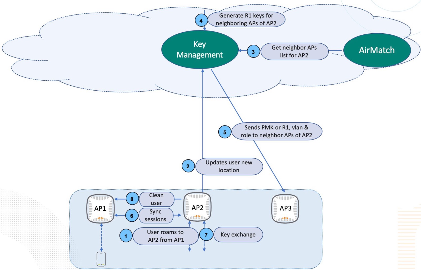
Bridged user roaming workflow with KMS
-
Following the initial association with AP1 and the completion of the first-time full authentication, the wireless user eventually transitions to neighboring AP2 during the course of their wireless session.
-
AP2 promptly updates KMS with the user’s new location, ensuring seamless handoff within the network.
-
KMS, driven by the user’s movement to AP2, retrieves the list of neighboring APs specific to AP2 from the AirMatch service.
-
Building upon this list of neighboring APs for AP2, KMS references the cached user station record, which includes PMK or R0 key, and generates R1 keys for each neighboring AP. This process is contingent on the utilization of the 802.11r fast roaming protocol, while the R1 key generation step is omitted if OKC roaming protocol is in use.
-
KMS commences the distribution of the user station record solely to those neighboring APs of AP2 that do not possess a cache of the user station record. This process avoids redundancy by excluding neighbors common to both AP1 and AP2.
-
AP2 initiates the synchronization of user sessions by transmitting a broadcast user session sync request message across the user VLAN. This synchronization action pertains to the top 120 user datapath sessions.
-
The user, now associated with AP2, engages in a four-way key exchange with AP2 as part of the seamless roaming process.
-
AP2 effectively communicates with AP1, instructing it to clear all entries related to the user, such as datapath entries. Subsequently, the user resumes data transmission through the new access point, AP2, ensuring a smooth and uninterrupted wireless experience.
Tunneled user roaming
In the realm of AOS 10, the implementation of a gateway cluster is highly recommended when network scalability becomes a primary concern. As networks grow to encompass a substantial number of APs, typically exceeding 500, or serve a significant client base that surpasses 5000 users, the introduction of a gateway cluster becomes essential. This architectural choice offers a multitude of advantages, including supporting large scale of APs and clients, centralized management of user VLANs, the establishment of unified firewall policies spanning both wireless and wired users, RADIUS proxy capabilities, and more.
With the presence of gateways, wireless users adopt a tunneled user configuration, where all of their network traffic is efficiently tunneled through the gateway cluster. This configuration eliminates the need for individual APs to manage user VLANs, centralizing this function at the gateway level. One notable advantage is that APs no longer need to belong to the same layer 2 domain for smooth client roaming. Consequently, when a tunneled user roams between different APs, their user session synchronization relies on seamless communication with their designated User Designated Gateway (UDG).
Illustrated below is a tunneled user executing fast roaming facilitated by KMS. This approach ensures network scalability while maintaining seamless and uninterrupted user experiences.

Tunneled user roaming workflow with KMS
-
Following a wireless user’s initial association with AP1 and the completion of full authentication, the user may eventually roam to a neighboring AP2.
-
AP2 promptly updates KMS with the user’s new location.
-
KMS, in turn, retrieves the list of neighbor APs associated with AP2 from the AirMatch service.
-
Leveraging this list, KMS fetches the user station record, encompassing the PMK or R0 key from its cache, and proceeds to generate the R1 keys for each neighboring AP present in the list if 802.11r fast roaming protocol is used for roaming.
-
KMS initiates the distribution of the user record to the neighboring APs of AP2 that lack the cached user station record. KMS refrains from repeating the station record distribution process for any APs that happen to be neighbors to both AP1 and AP2.
-
AP2 broadcasts a user session synchronization request message over the user VLAN.
-
The User Designated Gateway (UDG) forwards this session synchronization message to the user’s original AP, AP1.
-
AP2 proceeds to synchronize the top 120 user datapath sessions with AP1.
-
A start accounting notice is dispatched by AP2 to the UDG.
-
When the UDG gets the start accounting packet, it changes the bridge or user entry to send traffic to the AP2 tunnel. If the user is the first one from that VLAN on AP2, the multicast group gets updated with the client’s VLAN information.
-
The user embarks on a four-way key exchange with AP2.
-
AP2 then notifies AP1 to perform cleanup, which includes purging all entries related to the user, such as datapath entries. Following this, the user begins forwarding traffic through AP2.
Non-fast-roaming users
In older versions of AOS 10, user cache synchronization, which included user key information, was exclusively reserved for fast-roaming users like 802.11r users, OKC users, or MPSK users. However, a pressing need arose for cache synchronization among non-fast-roaming users, such as Captive Portal users and MAC authentication users. This need stems from the desire to prevent reauthentication when these users transition from one access point to another. To address this requirement, cache synchronization between neighboring APs was introduced and has been supported from AOS 10.4 onwards.
Cache classification
To optimize cache distribution, cache entries are classified into three distinct types:
-
Partial Roam Cache: This cache structure exclusively contains essential information necessary during roaming. For non-fast-roaming users, the partial roam cache is synchronized with neighboring APs.
-
Full Roam Cache: In addition to the data found in the partial roam cache, the full roam cache includes supplementary station-related state information that may not be immediately required during roaming. The full roam cache entry is consistently available in KMS and on the AP to which the client is currently associated.
-
Key Cache: This specific cache structure is exclusively employed by fast-roaming users. It houses station keys essential for fast roaming, including PMK (Pairwise Master Key), PMKR0, PMKR1 (per-BSSID), and MPSK, alongside comprehensive full roam cache information.
Workflows
Initial state
The diagram below provides an overview of the process for creating and synchronizing cache entries among neighboring AP for non-fast-roaming users.

Cache entry creation and synchronization for non-fast-roaming users
-
The user establishes a connection with the AP and successfully completes the authentication process.
-
In this step, the AP generates a full roam cache entry. Within this full cache entry, the partial roam cache information includes user-specific details such as user role, user VLAN, username, ESSID, and sequence number. In addition to the partial roam cache, the full cache incorporates various user state attributes like Class ID, multi-session ID, idle/session timeout, and more.
-
The AP transmits the full roam cache information of the user to KMS.
-
KMS retrieves the list of neighboring APs associated with this particular AP.
-
KMS proceeds to distribute the partial cache information of the user to all the neighboring APs linked to the same AP. This ensures that neighboring APs possess the essential cache data for seamless user roaming and authentication.
Roaming
The roaming workflow for non-fast-roaming users closely resembles that of fast-roaming users, with a notable distinction: the complete roam cache is exclusively retained by the AP and KMS, while only a partial roam cache is distributed to neighboring APs.
Illustrated below are the primary steps in the roaming process for non-fast-roaming clients.

Non-fast-roaming user roaming workflow with KMS
-
The user initiates a roam from AP1 to AP2.
-
AP2 transmits a roaming notification to KMS.
-
KMS retrieves the list of neighboring APs for AP2 from the AirMatch service.
-
KMS dispatches the partial roam cache for this user to the neighboring APs of AP2, excluding those that overlap with AP1. For instance, in this scenario, AP3 is a common neighbor of both AP1 and AP2. Since AP3 already received the partial roam cache when the user initially connected to AP1, KMS only sends the partial roam cache to AP4 at this stage.
-
AP2 sends a broadcast session synchronization request within the user’s VLAN to AP1 in an underlay scenario, to AP1 via AP2’s UDG in an overlay scenario, or within the default VLAN of the SSID if the cache is unavailable on AP2.
-
AP1 responds to the session synchronization request by sharing the top 120 user sessions.
-
AP2 forwards a user move request to AP1.
-
AP1 acknowledges the move request.
-
KMS dispatches the user’s complete roam cache to the AP2 to which the user has roamed.
-
AP2 initiates an accounting start message to AP1 in an underlay case or to the AP2’s UDG in an overlay case.
-
AP1 undertakes user entry cleanup, deletes the user’s full roam cache, and installs the partial roam cache. In an overlay scenario, the AP2’s UDG updates the bridge or user entry to direct traffic toward the AP2 tunnel. If the user marks the first instance of that VLAN on AP2, the multicast group is updated with the client’s VLAN information.
Configuration
To configure fast roaming in AOS 10, follow these steps:
-
Navigate to the WLANs section and select the specific SSID you want to configure.
-
Access the Security tab on the AP configuration page.

Fast roaming configuration
By default, 802.11r fast roaming is enabled, while OKC is disabled.
For optimal 802.11r configuration, it is highly recommended to set up the Mobility Domain Identification (MDID). MDID represents a cluster of APs that create a continuous radio frequency space, allowing 802.11r R1 keys for devices to be shared and enabling fast roaming.
Additionally, it is recommended to enable 802.11k. This standard facilitates swift AP discovery for devices searching for available roaming targets by creating an optimized channel list. As the signal strength from the current AP weakens, the device scans for target APs based on this list.
When 802.11k is enabled, 802.11v is automatically activated in the background. 802.11v facilitates BSS (Basic Service Set) transition messages between APs and wireless devices. These messages exchange information to help guide the device to a better AP during the 802.11r fast roaming process.
Verification
Command Line Interface
AP CLI command for checking the PMK or R1 key caching of wireless users of the AP:
show ap pmkcache

APIs
-
Retrieving the neighbor APs list for an AP:
URL:
https://<central-url>/airmatch/ap_nbr_graph/v1/Ap/NeighborList/<AP Serial Number> -
Retrieving the client record:
https://<app-url>/keymgmt/v1/keycache/{client_mac} -
Retrieving the encryption key hash:
https://<app-url>/keymgmt/v1/keyhash -
Retrieving the client key synced AP list:
https://<app-url>/keymgmt/v1/syncedaplist/{client_mac} -
Retrieving the stats per AP:
https://<app-url>/keymgmt/v1/Stats/ap/{AP_Serial} -
Checking on the health of KMS:
https://<app-url>/keymgmt/health
Survivability
Client roaming
In scenarios where connectivity to HPE Aruba Networking Central is lost during a roaming event, the station records and roam cache information of existing users have typically been synchronized among neighboring APs. Consequently, the fast roaming experience for these users remains unaffected.
It is, however, possible that during a network outage, the station records or cache information for new users cannot be synchronized among neighboring APs. In this scenario:
-
For new users who roam during this period, their user devices will undergo full authentication during the roaming event.
-
Despite the full authentication process, these users will continue to enjoy uninterrupted service.
In summary, while connectivity issues with HPE Aruba Networking Central may necessitate full authentication for new users, it does not disrupt their ongoing communications on the network.
Cloud fallback
In light of the earlier sections detailing user roaming workflows, it is important to highlight that there are two specific steps in which the new AP might not receive a response from the previous AP due to a timeout in the network:
-
Datapath session synchronization: In this phase, the new AP attempts to synchronize datapath sessions with the previous AP.
-
User state cleanup in the previous AP: During this step, the new AP requests the previous AP to clean up user-related information.
To address potential timeouts in these situations, KMS employs the Cloud Fallback mechanism. When a session synchronization or user state cleanup request times out, the new AP communicates with KMS to report the lack of response from the previous AP. KMS then searches the client-AP association table. If a client entry is found, KMS facilitates the communication between both APs, enabling them to coordinate the above-mentioned steps effectively.
1.4.3 - IoT operations
Aruba Central supports transporting of IoT data over enterprise WLAN. APs receive data from the IoT devices and send the metadata for these devices to Aruba Central and the IoT data to external servers through IoT Connectors. The IoT Connector aggregates the device data, performs edge-compute, and runs business logic on the raw data before sending the metadata and IoT data. The metadata for all IoT devices is displayed in IoT Operations dashboard in Aruba Central. Partner-developed applications, running on the IoT Connector, can be used to send the IoT data to external servers.
While enabling new capabilities to address real business needs, this proliferation of IoT devices at the edge creates a new set of challenges for IT. IoT devices use a variety of different physical layer connectivity types and communication protocols. Vendor-specific IoT gateways are often required to manage those devices and collect their data. IoT gateways obscure IoT devices on the network, making it difficult—if not impossible—to understand at a granular level what is connected to the network and where device data is going. Security is always front-and-center when it comes to IoT because many IoT devices are fundamentally untrustworthy, and the lack of visibility creates greater risk. IoT Operations within Aruba Central provides a solution to all of these problems.
Aruba’s IoT ecosystem mainly relies on its partner integrations. Aruba provides a transport medium in the form of its APs and a IoT Connector at the edge, for the data sensed by the IoT devices from different vendors and send that securely and efficiently to their backend.
Solution components
The IoT Operations consists of the following three solution components:
IoT dashboard
The IoT dashboard provides a unified view of all your IoT Connectors, Access Points sending IoT data to these connectors, Apps that are currently installed and a comprehensive list of all the IoT devices/sensors that are being heard by your Access Points.
It gives a detailed overview of how your IoT network is performing. The IoT dashboard provides a view of non-Wi-Fi IoT devices that would otherwise be obscured by vendor or device-specific hardware. IT can monitor these devices from the first moment they connect to APs anywhere in the environment and see exactly which AP each device is connected to. Once an appropriate App is installed on the IoT connector, previously unknown devices of that type can be automatically and accurately classified, so network administrators know exactly what the IoT devices are, and where the IoT devices are, with confidence. To learn more about monitoring IoT operations, refer to Monitoring HPE Aruba Networking IoT Operations.

Representation of IoT Ops Home Page
IoT app store
The IoT app store takes the complexity out of deploying new IoT use cases within the organization. Simply visit the IoT app store—located within Central—and use the store’s intuitive interface to browse ArubaEdge IoT applications certified to integrate seamlessly with our networks. Unlike directory-style marketplaces that simply provide pointers to compatible applications, the IoT app store provides certified applications for immediate download and activation with just a few clicks of the mouse. To install a Partner-Developed App refer to Installing a Partner-Developed App
Using the IoT app store also simplifies the complex and often confusing task of IoT device- application configuration. After the application is installed on the IoT connector, the AP can be easily configured to securely transport the device’s telemetry data to the appropriate destination, whether that’s an on-premises server or the cloud. From BLE location tags, beacons, and sensors to Zigbee door locks, IoT deployment is simple—so you no longer need to rely on third-party integrators for custom development. To know what IoT Apps are supported today, refer to IoT Operations App Matrix

IoT Operations App Store
IoT connector
Intelligent Edge applications which require edge computing of IoT data have historically been some of the most difficult for IT to implement and manage. The challenges are particularly acute when it comes to processing IoT data. In some cases, IoT Connector at the edge is needed to parse/decode IoT telemetry data from Central-managed APs and make the data available to IoT applications, whether hosted on premises or in the cloud (e.g., Microsoft Azure IoT Hub). In other instances, the AP itself can be used as a connector to securely transport the data.
The IoT Connector aggregates the device data, performs edge-compute, and runs business logic on the raw data before sending the dashboard metadata and IoT data. The IoT connector puts Intelligent Edge applications within reach—allowing IT to accommodate whatever technology transition comes next with the speed and ease of deploying a virtual machine or AP in the existing infrastructure. With the Aruba IoT connector component, it’s easy to provision multiple ArubaEdge IoT applications within the environment—it only takes a few clicks. The IoT connector virtual appliance is added as a new data collector within Central and then installed on the VM instance or AP. The administrator can then enable new IoT connectors through the IoT Operations guided user interface and see connectors in use—all within Central.
Each customer deployment can have different IoT Connector in their environment based on the scale of their deployment. IoT Operations supports the following specifications:
| Parameter | Mini VM | Small VM | Medium VM | DC-2000 |
|---|---|---|---|---|
| APs | 50 | 250 | 1000 | 1000 |
| BLE Devices | 2000 | 5000 | 20000 | 20000 |
| Zigbee Devices | 200 | 500 | 2000 | 2000 |
DC-2000 is a physical appliance
The IoT Connector support the following specifications:
| Parameter | Mini VM | Small VM | Medium VM | DC-2000 |
|---|---|---|---|---|
| CPU(Cores) | 4 | 8 | 24 | 24 |
| Memory(GB) | 4 | 16 | 64 | 64 |
| Storage(GB) | 256 | 256 | 480 | 512 |
Deployment models
IoT Connector is an integral part of the IoT Operations solution, providing connectivity and edge processing for IoT use cases. These Connectors are used to parse or decode IoT telemetry data from Central-managed APs and make the data available to partner IoT applications that are either hosted on premises or in the cloud. There are two deployment types available: virtual machine (VM)-based using VMWare ESXi or Aruba AP-based. For downloading and deploying an IoT Connector refer to Downloading IoT connector
VM based IoT connector
A VM-based IoT Connector leverages Aruba’s Data Collector architecture and is provisioned within Central. Configuration of the IoT Connector is provided within IoT Operations, using the guided user interface.

IoT Operations Architectural Diagram
AP as IoT connector
For customers who find it difficult to deploy and manage a separate machine outside of their wireless deployment, Aruba provides an option of using the existing AOS 10 APs as IoT Connectors. In this type, as compared to the previous model, the function of the IoT connector is collapsed into the AP.
However, the scale and the capacity of the IoT Connector would be less if it is running on an AP. In this model, only classifier apps like iBeacon, Eddystone, Blyott etc could be used, as the installation of heavy containerized apps like Dormakaba is not supported. Support for container-based Apps inside APs to come in future releases on Aruba Central. For creating AP-based IoT connector refer to Creating AP-based IoT Connector
Only 5xx and 6xx series APs are supported in this deployment model.

IoT Operations Architectural Diagram with AP acting as IoT Connector
Types of IoT solutions
BLE based
BLE or Bluetooth Low Energy based IoT solutions are the most common amongst all the types of IoT solutions. This is mainly because BLE as a technology is very common, easily available, could be implemented with relatively low effort and rather easy to connect. BLE which is basically Bluetooth version 4.0, was introduced for over a decade ago now and found its way to a variety of different applications and solutions. Today, most of BLE based IoT devices that Aruba supports are based on BLE 5.0.
How it works with IoT operations
The way most of the BLE devices are designed is that they broadcast their BLE beacons at pre-defined regular intervals which consists of raw data along with their payloads. Once a radio profile is configured and enabled on Aruba APs, they will start listening to these beacons and transport them over to the IoT Connector. Now within the IoT Connector, apps are installed to classify these devices and various filters could be applied to only forward that data which is relevant to the partner backend. In case of simple classifier apps like Aruba Devices, iBeacons, Eddystone, Blyott or Minew to name a few, there is no need for container-based workflow in the backend. This makes such apps very easy and quick to build and deploy. More complex solutions like on the BLE based door lock solution that utilize southbound API options necessitates the use of a container.
Use cases
High value asset tracking, location tracking, indoor navigation and wayfinding are the current most common use cases for this type of BLE-based solution in IoT Operations in AOS 10.
Zigbee based
AP’s built-in IoT radio, which supports 802.15.4 use case like Zigbee is used for providing gateway services to relay the Zigbee-based sensor data to a management server. As of today, Aruba mainly supports two smart door lock vendors as far as Zigbee based solution is concerned.
This allows an administrator to avoid deploying a network of ZigBee routers and gateways to provide connectivity to each door lock. A single network can handle both Wi-Fi and ZigBee devices. An AP from Aruba provides ZigBee gateway functionality that offers a global standard to connect many types of ZigBee networks to the Internet or with service providers.
ZigBee devices are of three kinds:
ZigBee Coordinator (ZC)—The ZC is the most capable device. It forms the root of the network tree and may bridge to other networks. There is only one ZC in each ZigBee network.
ZigBee Router (ZR)—A ZR runs an application function and may act as an intermediate router that transmits data from other devices.
ZigBee End Device (ZED)—A ZED contains enough functionality to communicate with the parent node (either a ZC or ZR). A ZED cannot relay data from other devices. This relationship allows the ZED to be asleep for a significant amount of time thereby using less battery.
An AP acts as a ZC and forms the ZigBee network. It selects the channel, PAN ID, security policy, and stack profile for a network. A ZC is the only device type that can start a ZigBee network and each ZigBee network has only one ZC. After the ZC has started a network, it may allow new devices to join the network. It may also route data packets and communicate with other devices in the network. Aruba solution does not utilize a ZR.
How it works with IoT operations
Compared to BLE, Zigbee based solutions differs in the fact that they need to directly connect to a coordinator. The configuration is generally more time and labour intensive given the nature of deploying such a solution given the one-by-one nature of putting the APs in permit-joining mode and connecting a given lock.
Zigbee use cases almost always require the use of container based IoT apps given the edge processing is needed to transform data in the payload. The two Zigbee based door lock vendors that are supported today with IoT Operations, require the transport detailed to be configured while installing the apps as opposed to configuring a separate transport stream.
Use cases
Smart Zigbee-based door locks mainly comprise of the current supported use cases as far as Zigbee is concerned. These are mainly seen in the hospitality industry and enterprises that use smart buildings and facilities. These solutions provide immense ease of use with simple NFC-based key cards or even mobile phones entry, along with providing appropriate security and very detailed analytics. Features like remote locking and unlocking of doors, key blocking, how many times was the door locked/unlocked, was the latch enabled or not are some of the basic smart features that are offered by these solutions.
USB based
All Aruba APs have a dedicated USB-A slot where external supported devices could be plugged and powered. One major benefit this provides is that it opens the spectrum of use cases that are not natively available from the IoT chipset in the APs. Essentially, the AP can run any proprietary protocols other than Wi-Fi, BLE or Zigbee making use of the USB slot.
One thing to note while using this is that the USB slot is strictly governed by ACLs, so unless a supported vendor’s dongle is plugged, the slot will not function or allow for connectivity.
How it works with IoT operations
The vendors that are supported today can be divided into 2 categories: Ethernet-over-USB and Serial-over-USB. Hanshow and SoluM fall under the 1st Ethernet-over-USB category and EnOcean falls under Serial-over-USB category.
Now apart from installing the vendor app itself, a transport stream or ‘AOS8’ app needs to be configured to specify its endpoint details.
Use cases
Hanshow and SoluM make the electronic shelf labels(ESL). These are widely used in the retail industries and warehouses. They are replacing the traditional price tags that had be managed manually, were cumbersome and required a lot of time, effort and cost. With these ESLs, all of the above problems could be managed digitally through a central management server.
EnOcean’ USB dongle is used in conjunction with a variety of sensors. The EnOcean Alliance is a federation of nearly 400 product vendors, manufacturing more than 5,000 different lighting, temperature, humidity, air quality, security, safety, and power monitoring sensors and actuators.
The table below shows a summary of the available transport services and the corresponding supported server connection types and device class filters:
| IoT Transport Service | IoT Radio Connectivity | IoT Server Connectivity | Device Class Filter |
|---|---|---|---|
| BLE Telemetry | Aruba IoT radio | Telemetry-WebSocket, Telemetry-HTTPS | All BLE device classes |
| BLE Data | Aruba IoT radio | Telemetry-WebSocket, Azure-IoT-Hub | All BLE device classes |
| Serial Data | USB-to-Serial | Telemetry-WebSocket, Azure-IoT-Hub | serial-data |
| Zigbee Data | Aruba IoT radio Gen 2 | Telemetry-WebSocket | zsd |
SD-Radio
SD-Radio or SDR is a new feature that allows our IoT partners to load their proprietary firmware onto the built-in IoT radio of the APs and then communicate with their backend server. This SDR can be enabled on both of our internal and external radios. Having support for this feature on external radios, enables the use of older AP models that did not have built-in IoT radio.
When a radio is software defined, it can accept new firmware from IoT App supported in Aruba Central. Once radio switches to the SDR, the App can communicate with the radio and run their logic and protocols which are transparent to Aruba.
Firmware images are stored in Openchanel’s file server. Central pushes the URL and APIKEY to the Connector and the Connector pushes them to the AP. AP downloads the image and then starts upgrading. If file servers need an SSL certificate for downloading image, AP images should embed it in advance. If current APs don’t have such certificate, Central needs to support upload Certificates to APs by customer.
Licensing
IoT Operations is available to Aruba Central customers using AOS 10 based APs, with Foundation and/or Advanced AP licenses. Separate licenses are not required for IoT Operations.
IoT Operations utilizes an IoT Connector to receive IoT data from APs and sends IoT device metadata to Aruba Central and IoT data to partner applications. The APs that are assigned to an IoT Connector utilize their IoT radios to act as IoT gateways for myriad IoT devices in the physical environment.
Aruba uses the license tier of APs assigned to your IoT Connector to determine the user experience. Currently, that user experience is differentiated in the IoT Operations Application Store. You will either have access to all apps in the IoT Operations Application Store or some of the apps in the IoT Operations Application Store. Regardless of license tier, the supported scale and base functionality of IoT Operations are the same. In the future, Aruba may add new capabilities to IoT Operations which may extend across apps or even be offered independently of the apps themselves. The user experience is currently determined in IoT Operations as:
-
When all APs assigned to an IoT Connector have an Advanced AP license, you have access to all apps in the IoT Operations Application Store.
-
When at least one AP assigned to an IoT Connector has a Foundation AP license, you have access to a subset of apps in the IoT Operations Application Store. The apps that are available are shown in full color, while the apps that are unavailable are shaded grey.
Filters can be used in the IoT Operations App Store user interface to further refine your app search. For more information on HPE Aruba Networking Central Licenses, refer to About HPE Aruba Networking Central Licensing
Key considerations and setup
This section describes some of the key considerations and brief steps involved for successful implementation of IoT Operations
-
APs need to run ArubaOS 10 code version
-
Configure IoT Radio Profiles and/or Zigbee Service Profiles
This configuration is required to enable AP’s IoT radio to listen to nearby BLE or Zigbee sensors. This piece of config is done outside of the IoT Operations home page, under AP config>IoT section.
-
Deploy an IoT Connector
IoT Connector can be deployed and managed under Organization>Platform Integrations>Data Collectors. From here an OVA file could be downloaded, the collector could be deployed and eventually registered to your Central account. Once everything is in place, you can start configuring the IoT Connector under IoT Operations home page.
-
Assign APs to IoT Connector
APs need to be assigned to a connector for them to transport the IoT data that is sensed by the APs to the connector. Multiple APs could be assigned to one connector. Conversely, one AP can only be assigned to one connector. This could be achieved under Applications>Connectors>Gear Icon.
-
Install Apps
Once inside your IoT Connector context, navigate to Installed Applications>Manage. This presents a list of all the available apps in the IoT Ops app store. To install any of them, simply open the app card and click Install. Most of the apps are classifier apps that don’t require any additional configuration. Some apps might require additional transport related configuration.
-
Create a Transport Stream
For the apps which are just classifier apps and don’t require any additional configuration, we need to configure a separate transport stream to send the IoT data to an endpoint. This could be done either using ‘AOS8’ app or creating a transport stream under connector >Transports.
Complete set of configuration directions can be found within the HPE Aruba Networking Central documentation.
1.4.4 - Tunnel orchestrator
The Overlay Tunnel Orchestrator (OTO) service architecture defines the working model of Tunnel Orchestrator service between Aruba Gateways and APs.
Aruba supports automated Tunnel Orchestrator for LAN Tunnels service for APs and Gateways deployed in campus WLAN. Based on the location of the devices, the tunnel orchestrator service establishes either GRE tunnels (at the branch site) or IPsec tunnels between Gateways and APs provisioned in an Aruba Central account (This has been described in greater detail in the following sections). The tunnel orchestrator service along with AP Tunnel Agent and Gateway Tunnel Agent creates and maintains the tunnels between APs and Gateways.
The Tunnel Orchestrator for LAN Tunnels service can be enabled either globally or on individual device groups. By default, the Tunnel Orchestrator for LAN Tunnels service is enabled for Gateways and AP devices provisioned in an Aruba Central account. The tunnel orchestrator automatically builds a tunnel mode network based on the tunnel endpoint preference that you configure in the WLAN SSID. The tunnel orchestrator selects the Gateway-AP pairs and decides the number of tunnels between the Gateway cluster and APs based on the virtual AP configuration.
Working
The Tunnel Orchestrator service leverages the Tunnel Orchestrator service of Aruba SD-WAN solution released in 2018. In ArubaOS 8, the tunnels between gateways and APs were built through the legacy IPsec process: Both end devices go through IKE phase 1 and phase 2 to authenticate each other, negotiate authentication method and timers, and generate encryption keys used for data traffic.
In ArubaOS 10, each gateway and AP pair does not directly go through IKE phase 1 and phase 2 to establish an IPsec tunnel between the gateway and the AP. Instead, the whole tunnel setup function is moved to the Tunnel Orchestrator service in Aruba Central which is responsible for generating the session keys and SPIs for the gateway and AP pair. These session keys are used to control traffic encryption between the AP and the gateway.
The different parts of the legacy IKE phase 1 process, such as authentication and encryption, timer negotiation, SPI pair generation, and encryption keys generation are skipped in the Tunnel Orchestrator service because all the gateways and APs are registered and subscribed in Aruba Central are treated as trusted entities. Secondly, the encryption policy and timers used by Aruba gateways and APs are hardcoded, there is no negotiation required. In ArubaOS 10, the tunnel orchestrator completely takes over the job of the IKE process and generates the keys and SPIs used for the IPsec tunnels. The Tunnel Orchestrator service not only simplifies the configuration model and device software, but also increases the performance and scalability of the whole network.
AP tunnel agent and gateway tunnel agent
The AP Tunnel Agent (ATA) and Gateway Tunnel Agent are the tunnel management modules in APs and Gateways respectively. They are responsible for handling all GRE and IPsec tunnel configurations and maintaining the status in APs and Gateways. ATA and Gateway Tunnel Agent provide the following functions:
-
Register the information of APs and Gateways with tunnel orchestrator service.
-
Receive Gateway cluster and tunnel information and distribute to other processes.
-
Create and maintain IPsec and GRE tunnel and survivability status.
Use cases of tunnel orchestrator
In ArubaOS 10, there are two scenarios where the tunnel orchestrator orchestrates tunnels for a pair of end points:
APs and gateways in a campus network
When a tunnel or mixed mode SSID is configured, tunnel orchestrator orchestrates an IPsec tunnel and a GRE tunnel between each AP in the AP group and each gateway member in the gateway cluster. For example, in a case of one AP and two gateways in a cluster as what is shown in the following diagram: the tunnel orchestrator orchestrates one IPsec tunnel and one GRE tunnel between the AP and the first gateway, and one IPsec tunnel and one GRE tunnel between the AP and the second gateway. The IPsec tunnel is used for control traffic between the AP and the gateway, such as bucketmap and nodelist updates. The GRE tunnel is used for user data traffic from all the configured SSIDs on the AP. The GRE tunnel is not encrypted by the IPsec tunnel to avoid double encryption and performance degradation. The security of user traffic is guaranteed by the encryption method used in the SSID.
Micro branch APs and gateways for remote offices and teleworkers
In a Micro Branch deployment, the GRE tunnel is encrypted by the IPsec tunnel. Since the data traffic between the AP and gateway goes through the WAN network, extra encryption becomes necessary.

GRE and IPsec Tunnels in Different Modes
Tunnel orchestrator workflow for creation of tunnel or mixed WLAN SSIDs
By now, we know that the tunnels are created between gateways and APs as soon as a tunneled SSID or a mixed SSID is created. At the time of this type of SSID creation, the user needs to select the gateway cluster to which the APs will form a tunnel to. Eventually this will tunnel all the wireless client traffic to the gateway cluster.
The process is automated to the extent that when a new AP or a gateway is added to the existing groups, Tunnel Orchestrator service will automatically build all the relevant new tunnels between all the devices.
If we were to look at the step-by-step workflow of the entire orchestration process when a new tunnel or mixed mode SSID is to be configured, it would include the following:
-
Tunnel SSID or mixed mode SSID is configured, and the service configuration module notifies the Tunnel Orchestrator.
-
The Tunnel Orchestrator queries the device configuration module about all the gateway members in the cluster on which the SSID terminates.
-
The Tunnel Orchestrator queries the group management module about all the APs in the AP group.
-
The Tunnel Orchestrator generates SPI and encryption keys of the IPsec tunnels and the GRE tunnels for each pair of AP and gateway member in the gateway cluster.
-
All the tunnel details are pushed to the gateways and APs.

Tunnel Orchestrator Workflow
Key considerations
To allow APs and Gateways to automatically establish tunnel modes, ensure that the following configuration tasks are completed:
-
Aruba Gateways are onboarded to a group in Aruba Central.
-
Aruba APs are provisioned in Aruba Central.
-
Aruba Gateways and APs are upgraded to ArubaOS 10.0.0.0 or a later software version.
-
A WLAN SSID with the tunnel forwarding mode is configured on the APs. When you create a new SSID, you must select the primary cluster name or Gateway where you want to establish tunnel traffic of the SSID. Optionally, you can select the backup cluster that can be used when the primary cluster goes down completely. The APs establish tunnel with the Gateways in a Gateway cluster.
-
If the overlay IPsec tunnels initiated by APs to a VPN Concentrator use NAT traversal, the UDP 4500 port is enabled.
IPsec SA rekeying
IPsec SA is created with a finite lifetime to ensure security. The AP-Gateway IPsec SA lifetime is 36 hours. The rekeying process ensures that there is no data loss during rekeying. Before the SA expires, the Tunnel Orchestrator performs rekeying for all the IPsec SAs of AP-Gateway pairs.
The following workflow explains the Tunnel Orchestrator IPsec SA rekeying process:
-
Twelve hours before the IPsec lifetime expires, the Tunnel Orchestrator starts IPsec SA rekeying and orchestrates new keys for AP-Gateway pairs.
-
New keys are pushed to the AP-Gateway pairs.
-
The gateway examines temporary ingress tunnels in learning mode.
-
The AP sends a probe encrypted with the new key.
-
Parallelly, all the control traffic is still exchanged between the AP and the gateway through the old IPsec tunnel.
-
After the gateway successfully decrypts the probe message with the new key, the gateway removes.
-
temporary learning mode tunnel and installs new ingress and egress tunnels with the new key.
-
The gateway sends a probe response to the AP.
-
The AP removes the temporary learning mode tunnel and installs new ingress and egress tunnels with the new keys.
-
The old tunnels remain active for 10 seconds for transient traffic.
-
All the control traffic is switched to the new tunnels.
-
Both the AP and the gateway age out the old tunnels.
Cloud survivability for tunnel orchestrator
Survivability is a feature to mitigate the IPSec traffic between Aruba devices whose IPsec tunnels are orchestrated by Cloud and has a definite key expiration time when the cloud connectivity fails for any unknown reason and the devices have still connectivity between them. With survivability, the devices should be able to re-establish IPSec tunnels between them based on the tunnel config which they have already received from Tunnel Orchestrator using the legacy IKE/IPSec tunnel establishment.
During the rekey phase, if cloud connectivity is lost, the devices will seamlessly switch over to legacy IPSec tunnels. Survivability can be triggered during the following situations:
-
Either side of the tunnel has no connectivity to Tunnel Orchestrator
-
Tunnel Orchestrator pushes new keys to APs and gateways, but they are not received
-
Tunnel Orchestrator does not push new key to APs or gateways
-
The devices are not able to bring up tunnels using received keys
Cryptomaps for all the tunnel config received are created irrespective of Initiator/Responder. But on the initiator side, cryptomaps are in disabled state. After 9 retries to bring the rekey tunnel up, cryptoMap on the initiators side will be enabled for the survival tunnel to be triggered.
Once the survivability tunnel is up, the same process will be started again during rekey.
1.4.5 - Live upgrade
Live upgrade services
The Live Upgrade and Firmware Management services in HPE Aruba Networking Central provide seamless upgrade of APs and gateway devices. The Live Upgrade service provides the following functions:
- Upgrades APs, gateway clusters, or both
- Allows the selection of the desired device firmware from a list of available versions
- Allows to schedule upgrades up to one month in the future
- Provides visibility of the upgrade progress
- Allows upgrade of multiple groups in parallel
- Allows termination of upgrades in the middle of the upgrade process
The Firmware Management service provides the user interface and other existing functions like firmware compliance and scheduled upgrades. The service also interfaces with the devices to initiate upgrades and receive upgrade status. The Live Upgrade service provides APIs to the Firmware Management service to initiate or abort live upgrades and decides the logic to orchestrate the upgrade process and the time of upgrade for the devices.
AP live upgrade
The Live Upgrade service enables the upgrade of APs without disrupting the connection of the already existing clients and reduces the upgrade duration by running parallel upgrades. The Live Upgrade service interfaces with the AirMatch service to partition all the APs that require upgrade into multiple smaller sets of APs that can be upgraded in parallel and each batch of APs will go for reload sequentially. AirMatch partitions APs based on RF neighborhood data such that neighboring APs are available for clients to roam to when the associated AP is undergoing an upgrade, so all the APs in one AP partition are in the same channel and are not in the same RF neighborhood.
To reduce WAN bandwidth consumption and upgrade duration, a set of APs, known as seed APs, are selected. Only these seed APs download the images directly from the Aruba Activate server. The rest of the APs download the image from its designated seed AP. Seed APs are selected based on the following considerations:
-
A non-seed AP is L2 connected to its designated seed AP.
-
A non-seed AP is of the same platform model as its designated seed AP.
-
Not more than 20 non-seed APs are assigned to a given seed AP.
-
Seed AP is randomly selected out of APs which are L2 connected and have same model type.
The following image shows the background process when an AP undergoes the Live Upgrade workflow.

AP Live Upgrade Process
The AP Live Upgrade workflow is as follows:
-
When the scheduled time arrives, the Firmware Management (FM) service sends the AP group details to the Live Upgrade service. The upgrade time can either be the current time or a scheduled time within a month.
-
The Live Upgrade service stores the AP list in the AP group and sets all the APs in the list, in the upgrade INIT state.
-
The Live Upgrade service retrieves the subnet information of the APs from the monitoring module in Aruba Central.
-
The Live Upgrade service selects seed APs based on seed AP selection criteria, and assigns a designated seed AP for each non-seed AP.
-
The Live Upgrade service retrieves the AP partition information from the AirMatch service.
-
The Live Upgrade service initiates an image upgrade of all the seed APs and sends the request to the FM service.
-
The FM service sends an image upgrade request to all the seed APs.
-
All the seed APs download the image from the Activate server.
-
After downloading the image, all the seed APs send upgrade responses and states to the FM service.
-
The FM service forwards the responses and states of all the seed APs to the Live Upgrade service.
-
The Live upgrade service initiates an image upgrade of all the non-seed APs and sends the request to the FM service.
-
The FM service sends an image upgrade request to all the non-seed APs.
-
All the non-seed APs download the image from their designated seed APs.
-
After downloading the image, all the non-seeds APs send upgrade responses and states to the FM service.
-
The FM service forwards the responses and states of all the non-seed APs to the Live Upgrade service.
-
The Live Upgrade service initiates the reboot for the first AP partition and sends the request to the FM service.
-
The FM service forwards the AP reboot request to all the APs in the AP partition, and all the rebooted
-
APs send reboot responses to the FM service after rebooting.
-
The FM service forwards reboot responses and states to the Live Upgrade service.
-
Remaining AP partitions are rebooted in sequence
Rebooting access points
After all the APs finish downloading the image, the Live Upgrade service starts the AP rebooting process. All the APs in one AP partition reboots at the same time. After the Live Upgrade Service receives updates on successful reboot of all the APs in the partition, the service initiates the reboot process for the next AP partition. This process is repeated until all the AP partitions reboot and come up with the new image.
The following is an example workflow of an AP reboot process:
-
The Live Upgrade service sends the AP reboot request for a specific AP partition to the FM service.
-
The request is sent to every AP in the partition.
-
After receiving the reboot request, each AP disables all its radios.
-
All the clients associated with the AP are unable to ping the AP and forced to roam to the neighboring APs.
-
All the neighboring APs associated with the clients perform a session sync with their previously associated AP.
-
The AP starts rebooting a few seconds later.

Reboot AP Process
The HPE Aruba Networking Central product documentation provides the steps required to perform or schedule the Live Upgrade service for APs.
Upgrading a gateway group
As gateways in a gateway group are much smaller in number, seeding and partition concepts are not necessary. To reduce upgrade duration, all the gateways in a cluster are instructed to download the image together. However, they are reloaded sequentially to avoid disruption. As only one gateway is reloaded at any given time, remaining cluster members together need free capacity for clients of only one gateway.
The Cluster UDG (User Anchor Gateway) concept ensures that all the users on a gateway are assigned standby UDG. The user state and Datapath sessions are synced to the standby UDG. When a gateway reloads, cluster failure detection logic detects the failure within a second and moves users to the standby UDG. With multi- version support added, when a gateway reloads with a new firmware version, it rejoins the cluster and can sync the user state and sessions with the cluster members running an older version. Users are not disrupted during the gateway upgrade process.
The gateway Live Upgrade workflow is as follows:
-
The FM service applies all the configured compliance rules which include gateway group names, the firmware version to which the gateway group needs to upgrade, the time at which the group needs to upgrade. The upgrade time can either be the current time or a scheduled time within a month.
-
When the scheduled time to upgrade arrives, the FM service sends the gateway group details to the Live Upgrade service.
-
The Live Upgrade service stores the gateway list in the gateway group and sets all the gateways of the list in the upgrade INIT state.
-
The Live Upgrade service initiates an image upgrade of all the gateways in the group and sends the request to the FM service.
-
The FM service sends the image upgrade request to all the gateways.
-
All the gateways download the image from the Activate server.
-
After downloading the image, all the gateways send upgrade responses and states to the FM service.
-
The FM service forwards the responses and states of all the gateways to the Live Upgrade ser-vice.
-
The Live Upgrade service initiates the reboot request to one of the gateways and sends the request to the FM service.
-
The FM service sends the reboot request to the gateway.
-
The gateway reboots.
-
The gateway sends reboot responses and states to the FM service.
-
The FM service forwards the reboot responses and states to the Live Upgrade service.
-
The rest of the gateways in the group are cycled through the reboot process in sequence.
The following image explains the Gateway Live Upgrade workflow:

GW Live Upgrade Process
The HPE Aruba Networking Central product documentation provides the steps required to perform or schedule the Live Upgrade service for gateways or gateway clusters.
Upgrading a device image
You can upgrade a device or multiple devices under the Firmware tab in Aruba Central. Any configured device group can be upgraded together or individually.
There are two upgrade types:
-
Live Upgrade
-
Standard
The default upgrade type is Standard. In this upgrade type, all the devices under the selected group download the images directly from the Aruba Activate server and reboot simultaneously. There is no consideration for reducing disruption to the network.
To perform Live Upgrade, set the upgrade type to Live Upgrade.
Firmware compliance configuration parameters:
-
Groups: You can choose All Groups, a single group, or a combination of groups
-
Firmware version: This is the target firmware version for the selected devices. There are three choices:
-
Choose a specific build number from the drop-down list.
-
Enter a custom build number, for example, 10.0.0.1_74637, and click Check Validity to validate the build number.
-
Set to None. When you set the option to None, set the compliance status as Not Set as you see in the screen capture. When you want to upgrade a device to a specific firmware version from your FTP server instead of Aruba Central, ensure that the Compliance Status is Not Set for the group to which the device belongs. Otherwise, Aruba Central automatically upgrades the group to the configured firmware version in Aruba Central and overrides the firmware version downloaded from your FTP server.
-
-
Upgrade type
-
Standard (default type)
-
Live upgrade
-
-
Upgrade time
-
Now
-
Later date: Firmware upgrade can be scheduled at a future time from the time of upgrade configuration up to one month later.
-
Refer to the HPE Aruba Networking Central product documentation for the specific steps required to perform or schedule the Live Upgrade service for different devices or device groups.
1.4.6 - RAPIDS
Rogue Access Point Intrusion Detection System (RAPIDS) automatically detects and locates unauthorized access points (APs), regardless of your deployment persona, through a patented combination of wireless and wired network scans. RAPIDS uses existing, authorized APs to scan the RF environment for any unauthorized devices in range. RAPIDS also scans your wired network to determine if the wirelessly detected rogues are physically connected. Customers can deploy this solution with “hybrid” APs serving as both APs and sensors or as an overlay architecture where Aruba APs act as dedicated sensors called air monitors (AMs). RAPIDS uses data from both the dedicated sensors and deployed APs to provide the most complete view of your wireless environment. The solution improves network security, manages compliance requirements, and reduces the cost of manual security efforts.
-
Rogue device detection is a core component of wireless security.
-
RAPIDS rules engine and containment options allows for creation of a detailed definition of what constitutes a rogue device and can quickly act on a rogue AP for investigation, restrictive action, or both.
-
Once rogue devices are discovered, RAPIDS can alert a security team of the possible threat and provides essential information needed to locate and manage the threat.
-
The RAPIDS feature set is included with Foundation subscriptions.

RAPIDS Flow
RAPIDS provides an effective defense against rogues and other forms of wireless intrusion. To accomplish these objectives, RAPIDS will:
-
Perform multiple types of wireless scans.
-
Correlate the results of the various scans to consolidate all available information about identified devices.
-
Classify the discovered devices based on rules that are customized to an organization’s security needs.
-
Generate automated alerts and reports for IT containing key known information about unauthorized devices, including the physical location and switch port whenever possible.
-
Deploy containment mechanisms to neutralize potential threats.
Key features & advantages of using RAPIDS
| Feature | Benefit |
|---|---|
| Wireless scanning that leverages existing Access Points and AM sensors | Time and cost savings. Eliminates the need to perform walk-arounds or to purchase additional RF sensors or dedicated servers. |
| Default or Custom Rules-based threat classification | Time and resource savings. Allows staff to focus on the most important risk mitigation tasks. Comprehensive device classification that’s tailored to the organization means less time spent investigating false positives. |
| Automated alerts | Faster response times. Alerts staff the instant a rogue is detected, reducing reaction time and further improving security. |
| Rogue AP location and switch/port information | Faster threat mitigation. Greatly simplifies the task of securing rogue devices and removing potential threats. |
| Reporting | Reduced regulatory expense. Comprehensive rogue and audit reports helps companies comply with various industry standards and regulatory requirements. |
| IDS event management | Single point of control. Provides you with a full picture of network security. Improves security by aggregating data for pattern detection. |
| Manual and automated containment | Continuous security. Improves security by enabling immediate action even when network staff is not present. |
RAPIDS use cases
Regulatory compliance is a key motivator that drives many organizations to implement stringent security processes for their enterprise wireless networks. The most common regulations are Payment Card Industry (PCI) Data Security Standard, Health Insurance Portability and Accountability Act (HIPAA) and Sarbanes-Oxley (SOX).
RAPIDS reporting is helpful for compliance audits
-
PCI DSS requires that all organizations accepting credit or debit cards for purchases protect their networks from attacks via rogue or unauthorized wireless APs and clients. This applies even if the merchant has not deployed a wireless network for its own use.
-
RAPIDS helps retailers and other covered organizations comply with these requirements. RAPIDS also enables companies to set up automated, prioritized alerts that can be emailed to a specified distribution list when rogues are detected.
-
Hospitals use RAPIDS to protect patient data as well as protect thier systems. They need to know if rogues exist on their network along with critical medical devices use for patient care.
WIDS vs RAPIDS
Wireless Intrusion Detection Service (WIDS) provides additional behavioral information and security for a wireless network by constantly scanning the RF environment for pre-defined wireless signatures. Intrusion detection is built into AOS and uses a signature matching logic, as opposed to RAPIDS usage of rule matching.
-
AOS can trigger alerts, known as WIDS events, based on the configured threat detection level: high, medium, or low.
-
WIDS events can be categorized into two buckets:
-
Infrastructure Detection Events
-
Client Detection Events
-
RAPIDS will consume WIDS events to present the event information in a clear and intelligible manner with logging and rogue location information. Security events rarely happen in isolation, the attack will usually generate multiple WIDS events so RAPIDS will merge the reporting of multiple related attacks into a single event to reduce the amount of noise.
-
RAPIDS in Central aggregates WIDS events and provides a method to view which events are getting raised in the environment.
-
Each event has a specific victim MAC address; events are aggregated for each of those victim MACs.
-
Multiple APs reporting the same event.
-
Several attacks against the same MAC.
-
-
-
Visibility in the UI, NBAPI, API streaming
-
Device classification is a combination of cloud processing and edge processing.
-
Aruba access points can discover Rogue access points independently, without intervention from Aruba Central (continuous monitoring).
-
Aruba Central classification takes precedence.
-
RAPIDS classifications
RAPIDS ranks classifications in the following hierarchy.
-
Interfering
-
Suspected Rogue
-
Rogue
-
Neighbor (Known Interfering)
-
Manually Contained (DoS)
-
Valid
In the lifecycle of a monitored AP, classifications can only be promoted (i.e.. go higher in the list – in other words left to right in the diagram below) and can never be demoted (ie. go back down to a lower value).
If a neighbor reaches one of the classifications, “Valid” (in orange), this is considered a ‘final state’. Meaning, the AP will stop applying its own classification algorithms on that AP and this is where the AP will remain (unless it is aged out, or if the user manually classifies it to something else).
This same behavior also applies to the custom rules. For example, if a neighbor AP is already classified as Rogue then even if it matches a rule, it will never be demoted to a Suspected Rogue.

RAPIDS ranks classifications in the following hierarchy: Interfering, Suspected Rogue, Rogue, Neighbor (Known Interfering), Manually Contained (DoS), Valid
This same behavior also applies to the custom rules. For example, if a neighbor AP is already classified as Rogue then even if it matches a rule, will never be demoted to a Suspected Rogue.
Configuring rules
After enabling RAPIDS in the UI, a set of 3 default classification rules will take effect.
For existing RAPIDS customers, these rules are the same rules that have been applied in previous releases. Maximum of 32 Single Rules can be configured. All criteria in a single rule uses an “AND” operand which means a rule will only be applied if all the criteria in that rule evaluate as a match.

Configuring custom rules

Creating a custom rule

Add one or more conditions to your rule
Classification Criteria
- Signal - The user will be able to specify a minimum signal strength from -120 to 0 dB
- Detecting AP Count - The number of detecting APs that can “see” the monitored AP 2 to 255
- WLAN classification – Valid, Interfering, Unsecure, DOS, Unknown, Known Interfering, Suspected Unsecure
- SSID Includes - Pattern for matching against the SSID value of a monitored AP.
- SSID excludes - Pattern for matching against the SSID value of a monitored AP.
- Known valid SSIDs - Match against all known valid SSIDs configured on the customer’s account. Regular expression matching
- Plugged into wired network - When there is a managed PVOS/CX switch and a neighbor AP is determined to be plugged into the wired network when the BSSID matches the first 40 bits of a known wired MAC address as reported by the switch.
- Time on network - Minimum number of minutes since monitored AP was first seen on the network
- Site - List of site IDs for which this rule applies. If not populated then apply rule to all sites.
- Band - The radio band of the monitored AP. 80211B (2.4 GHz), A (5 GHz), G (2.4 GHz), AG (Not Used), 6GHz
- Valid client MAC match - Match any monitored BSSID against the current valid station cache list. This must be an exact match.
- Encryption - Encryption: OPEN, WEP, WPA, WPA2, WPA3
Rule ordering matters; rules are evaluated from top to bottom in the custom rule list.
Whenever a match is found; then that rule is executed and further rule evaluation is stopped.
Because of this, it’s important to order your rules from lower classifications to higher classifications.
Manual classification will be respected; if a neighbor AP has already been manually classified by the user then no rules will be evaluated for that AP.
If the classification rule selects a non-final state classification (ie. Interfering or Suspected Rogue), then AP rogue detection algorithms will continue to be applied at the edge. And theoretically they could determine that the AP is in fact a rogue and promote the classification to Rogue.
Rogues panel
The rogues panel provides a lot of detailed information about your wireless environment. Here is an example of what information is provided.

Rogues Panel
1.4.7 - AirMatch
Running within HPE Aruba Networking Central, AirMatch has the duty of computing an optimal radio frequency (RF) network resource allocation. AirMatch runs on a 24 hour cycle, first collecting RF network statistics and then developing an optimized RF network plan, which specifies channel, bandwidth, and EIRP settings for each radio, that is deployed once every cycle. As a best practice, the RF plan change should be deployed at the time of lowest network utilization so that radio channel changes have a minimal impact on user experience. In addition to the planning done every 24 hours, AirMatch also reacts to dynamic changes in the RF environment such as channel quality, radar, and high noise events. AirMatch results in a stable network experience with greatly minimized channel and EIRP variations. AirMatch is defined by the following key attributes:
- A centralized RF optimization service
- Newly defined information collection and configuration deployment paths
- Models the network into partitions and then solves the different partitions as a whole
- Results in optimal channel selection, bandwidth size, radio operating band (for Flex Dual Radio APs), and EIRP plan for the network
If the link between the access points and Central goes down, then features which require the coordination of Central, such as scheduled updates for RF optimization, will be lost. The current RF solution will continue to function and reactive changes resulting from high noise events and radar will still occur.
AirMatch workflow
The AirMatch workflow occurs using the following steps:
- APs send RF statistics to Central
- The AirMatch service in Central calculates the optimal RF solution
- AirMatch divides the network into separate partitions
- AirMatch then calculates the optimal channel plan for each partition
- AirMatch evaluates if the new channel plan for this partition is a sufficient improvement or not
- If sufficiently improved, AirMatch pushes the solution to the access points at the scheduled time
- Provides neighboring APs list to the Key Management Service
- Provides AP partition information to the Live Upgrade Service
AirMatch configuration
AirMatch was developed to operate with no user input, but instead based on readings taken from the RF network, and as such offers very little in terms of configuration. Constraining the parameters used to help fine tune the behavior is possible, but AirMatch should function correctly without any additional or specific configuration in most cases. Please consult the AOS 10 configuration guide to find this information.
Wireless coverage tuning
By default, the wireless coverage tuning is set to Balanced. This can be adjusted so that a channel plan improvement quality threshold which ranges from 0% (aggressive) to 16% (conservative) can be configured. By default, the Balanced setting represents 8% quality threshold improvement.
To determine the channel plan improvement index, the average radio conflict metric is computed. For each radio of an AP, channels that overlap with neighbors are calculated and path-loss is used to calculate a weighted conflict value. The closer the AP with the overlapping channels, the lower the path-loss and consequently, the higher the conflict. After AirMatch comes up with a new channel plan, the conflict value is compared with the current operating network and an improvement percentage is calculated. If the improvement percentage is higher than or equal to the configured quality threshold (8% by default), then the new channel plan is deployed to the AP at the scheduled time as configured.
Channel quality aware AirMatch
Channel quality, which is represented as a percentage, is a weighted metric derived from key parameters that can affect the communication quality of a wireless channel, including noise, non-Wi-Fi (interferer) utilization and duty-cycles, and certain types of retries. Note that channel quality is not directly related to Wi-Fi channel utilization, as a higher quality channel may or may not be highly used.
1.4.8 - ClientMatch
The ClientMatch service continuously gathers RF performance metrics from mobile devices and uses this information to intelligently improve the client’s experience. Proactive and deterministic, ClientMatch dynamically optimizes Wi-Fi client performance, even while users roam and RF conditions change. If a mobile device moves out of range of an AP or RF interference impedes performance, ClientMatch steers the device to a better AP to maximize Wi-Fi performance.
ClientMatch is aware of each client’s capabilities while also being aware of the Wi-Fi environment, this puts ClientMatch in the best position to maximize the user experience of each device as we know which radio each station is most likely to have the best experience on. In doing so, ClientMatch is also able to improve the experience of the entire system as slow clients on an access point also affect the experience of other users.
ClientMatch does this by maintaining a list of radios each station can see which is basically a database that states which access point radio that has been able to see the client’s device, and at which signal level. This information is then used, with a list of rulesets, to enhance the user’s experience.
The main difference between AOS8 and AOS10 regarding ClientMatch is that the orchestration of this feature is now handled by Central in the cloud instead of on a Mobility Conductor.
Move types
There are two types of moves, deauth moves and BSS Transition Message moves, also known as 802.11v message moves.
Deauth moves function by sending a de-authentication frame to a connected station and then not letting this station associate anywhere but to the desired radio for a duration of time after the frame is sent.
802.11v or BSS Transition Messages are an Action Frame sent out by the AP to the station suggesting that they should instead be moving to that BSSID. Keep in mind that these frames are not mandatorily obeyed by the station and are sometimes ignored or rejected. If that happens 5 or more times, ClientMatch will then trigger a deauth move instead.
Band steer
When ClientMatch sees an authentication being attempted by a station on the 2.4 GHz radio and he station is known to be 5 GHz or even 6 GHz capable, ClientMatch will then not let the client device connect to the 2.4 GHz band, effectively forcing them up to the more efficient bands.
ClientMatch will only attempt to move clients on 2.4 GHz with a worse signal then -45 dBm onto a target radio with a RSSI on 5 or 6 GHz that is better than -65 dBm.
6 GHz band steering can be disabled using the REST API.
Sticky steer
This feature comes into play in a scenario such as when a station associates to an access point while within the prime coverage area and then moves away to the edge of the coverage of the radio but the station does not roam voluntarily. ClientMatch is then aware that there is an access point that would be a better option for the station and as such is able to tell the client to move to the better candidate.
Load balancing steer
This is a feature that is more frequently used in high density environments such as auditoriums. Load balancing aims to balance out the number of clients on a per-radio basis as to make sure not all clients are connected to the same radio and that instead the load is split across the network.
This move type only uses 802.11v moves and does not attempt to do deauth moves as the clients do not fully understand the load component involved in the computation and might see a degradation in signal strength as a negative outcome.
This specific move type can be disabled using the REST API.
MU-MIMO steer
The goal of this is to move stations that are MU-MIMO capable so that they are on the same radios so that the AP can leverage the MU-MIMO function as two stations of appropriate types are necessary for an access point to be able to do MU-MIMO.
Un-steerable clients
Some stations refuse to cooperate with ClientMatch and as such will be put into an un-steerable station list for 48 hours if there has been three unsuccessful deauth steer attempts or for 24 hours if the client device ignores more than five consecutive 802.11v moves.
This list of un-steerable clients can be viewed using the REST API. Client devices known to not support being steered by ClientMatch can be added permanently to the un-steerable list by
using the REST API.
Disabling ClientMatch
Should ClientMatch be suspected of causing issues in the network, or if there is a desire or requirement to allow the devices to choose the connected access point without attempts for steering, then ClientMatch can be disabled using the REST API.
ClientMatch monitoring
In the Network Operations app, set the filter to Global.
-
Under Alerts & Events, click Events. The Events page is displayed.
-
Click on the CLICK HERE FOR ADVANCED FILTERING toggle to bring down the filtering options.
-
Click the ClientMatch Steer option.
-
Click the Filter button on the right.

Event viewer showing ClientMatch events in Central.
1.5 - Survivability
The purpose of this article is to capture the impact to clients, AOS-10 devices, and services if an outage prevents the AOS-10 devices from communicating with HPE Aruba Networking Central.
Client devices
The following table captures the impact to client devices, roaming experience and traffic flows during an outage.
| Feature or Service | Impact |
|---|---|
| Application Visibility | As enforcement is provided by access points (APs) and gateways, the classification and enforcement applications and categories will continue with no loss of functionality. Reporting of application visibility metrics to Central will be lost during the outage. |
| Authentication |
|
| ClientMatch | As ClientMatch services reside in Central, no client steers including sticky clients, band steering and load-balancing will occur. Clients will still be able to attach and roam, but in a less optimized environment. |
| Roaming | Fast roaming is dependent on the Key Management Service (KMS) in Central to pre-distribute keys and user records. Some impact to fast roaming may occur:
|
| UCC | Reporting of call metrics to Central will be lost during the outage. Wi-Fi calling will also be unavailable if the service providers evolved packet data gateway (e-PDG) is unreachable. |
| WebCC | As WebCC is dependent on BrightCloud, there may be some impact to traffic flows for unclassified applications when a cache miss occurs:
|
Managed devices
The following table captures the impact to AP and gateway management and data-plane during an outage:
| Feature or Service | Impact |
|---|---|
| AirGroup | As the AirGroup service resides in Central, no new discovery information will be propagated to APs. Existing cached information will be maintained but not updated. |
| AirMatch | As the AirMatch service resides in Central, APs will continue to function with their existing channel, channel bandwidth, and EIRP settings and will respond to high noise and radar events. The APs will not receive newly calculated channel plan assignments from the AirMatch service until they are able to reconnect to Central. |
| Cloud Connect | See Tunnel Orchestration. |
| Clustering | Gateway Clustering is dependent on the Group / Site configuration in addition to Tunnel Orchestration:
|
| DRT | As downloadable regulatory table (DRT) upgrades are dependent on Central, no DRT update will occur. APs will continue to function uninterrupted using their existing regulatory information. |
| IDPS | All devices will continue to function uninterrupted using their existing signatures. |
| Licensing | Devices will continue to function uninterrupted. |
| Mesh | Mesh operation is dependent on configuration from Central:
|
| MultiZone | See Tunnel Orchestration. |
| One Touch Provisioning (OTP) | As OTP is dependent on Activate and Central, no new APs or gateways can be provisioned. |
| Route Orchestration (ORO) | As the Route Orchestration service resides in Central:
|
| Tunnel Orchestration (OTO) | As Tunnel Orchestration services reside in Central:
|
| Security Policies | All devices will continue to function uninterrupted using their existing security policies. |
| Zero Touch Provisioning (ZTP) | As ZTP is dependent on Activate and Central, no new APs or gateways can be provisioned. |
Services
The following table captures the impact to services either consumed in Central or coordinated between Central and devices during an outage:
| Feature or Service | Impact |
|---|---|
| Configuration Management | As configuration is dependent on Central, you will lose the ability to apply new configurations or make configuration changes to impacted devices. APs and gateway will continue to function using their existing configurations. |
| Events | No events will be triggered for impacted devices during the outage. |
| Firewall Logging | Reporting of firewall flows to Central will be lost during the outage. |
| IoT Operations | As the IoT connector services reside in Central:
|
| Location Services | As location services, Visual RF and API services reside in Central:
|
| Monitoring | All monitoring information will be lost for impacted devices. This includes APs, gateways and Clients. |
| Presence Analytics | Presence Analytics data in the Dashboard for impacted sites will not be updated. |
| RAPIDS WIDS/WIPS |
As the RAPIDS services reside in Central:
|
2 - Wi-Fi design and deployment
2.1 - Wi-Fi design guides
2.1.1 - Warehouse
Warehouse environments present unique challenges in Wi-Fi design, due to factors like high ceilings, metal shelving, dynamic inventory levels, and environmental conditions. This guide offers a comprehensive approach to designing robust and reliable Wi-Fi networks tailored to warehouse environments.
Challenges
- Large spaces: Warehouses often have vast, open areas that require extensive coverage. Each AP typically covers a larger area, ranging from 3,000 to 8,000 square feet (900 to 2500 square meters), compared to smaller indoor environments.

Example of a large open warehouse space
- Tall structures and obstacles: The height of warehouse ceilings and storage racks, combined with heavy shelving and large equipment, adds complexity to coverage planning. These factors create physical obstructions that can interfere with signal propagation.

Example of tall ceilings and storage racks

Example of tall storage racks
-
Variable Climate Control: Temperature-controlled areas such as refrigerated or freezer zones create challenging RF conditions. Extreme cold, insulated walls, and sealed doors can alter signal propagation, cause condensation on equipment.
-
AP mounting and cable management: Due to the unique warehouse layout, finding suitable mounting locations for APs can be difficult. Additionally, planning for power and data cable runs needs to account for both vertical space and potential obstacles.
-
Inadequate indoor APs: Standard indoor APs often struggle to cover the long distances and large spaces typical of warehouses. This necessitates the use of more powerful, specialized APs.
-
While APs utilizing external antennas, also known as connectorized APs, may offer more flexibility, they add both hardware and labor costs. They also introduce the potential for greater risk during installation and future maintenance.
Key design considerations
-
Warehouse size: The overall square footage will dictate the number of APs needed for adequate coverage.
-
Ceiling height: Taller ceilings require higher-powered APs or more APs to ensure signals reach the ground.
-
Rack height: The space between the AP and the top of rack impacts how the signal propagates.
-
Client density: The number of devices that will be connected to the network at any given time impacts both throughput requirements and the number of APs needed to handle traffic. In warehouses, device density is typically much lower than in an office space, but coverage still needs to support scanners, handhelds, and IoT devices reliably.
-
Location or wayfinding: If the design includes location-based services (e.g., asset tracking or employee navigation), this must be factored into the network’s design to ensure accuracy and reliability.
-
Types of goods stored: Different materials and objects stored on shelves can influence signal strength due to varying levels of radio interference.
-
Hostile Environmental Conditions: Unlike office buildings, many warehouses are partially exposed to the elements and lack consistent heating or cooling across the entire space. This subjects networking equipment to greater temperature fluctuations and harsher conditions. An example of an additional challenge that is not uncommon is the presence of bird or rodent nests in rafters or eaves.

Example of storage
-
Layout and content changes: Warehouses are dynamic environments where layout and inventory can change frequently. The Wi-Fi design should be adaptable to these changes, ensuring reliable coverage even as the space evolves.
-
Outdoor areas: If the design extends beyond the warehouse building (e.g., docks, yard spaces), outdoor APs or mesh networks may be necessary.
-
Client types: Different types of devices, such as scanners, tablets, forklifts, and mobile phones, may have varying power requirements and need to be considered when designing the network.
These factors should be considered to create a robust and scalable Wi-Fi design that accommodates the unique challenges of warehouse environments.
AP placement strategies
There are two main options for HPE Aruba Networking Access Points placement: ceiling mounting and wall mounting. Each method has pros and cons, and in some cases, one may not even be feasible depending on the environment.
Ceiling mount
Ceiling placement is often the ideal choice for warehouse environments, offering several advantages:
- Better Coverage: Ensures more uniform coverage along the floor, reducing RF propagation, especially in the 2.4 GHz range.
- Less Interference: Minimizes signal obstruction from moving equipment or products.
- Staggered Placement Flexibility: Works well with staggered AP placement, where adjacent aisles benefit from coverage despite no AP being directly overhead.
- Ideal for Large Spaces: Ceiling mounts are more adaptable for large warehouses, providing broader coverage and easier access for maintenance.

Ceiling mount pattern

5 GHz band coverage of ceiling mounted omnidirectional APs (AP-565) at 10 m (32 ft) above ground level.
To understand the color-to-coverage mapping, refer to Visualization settings and heatmap.
Wall mount
While wall mounting is often a secondary option, this method can still be effective in certain situations, such as when ceiling placement isn’t possible. However, wall mounting comes with some limitations:
-
Focused Coverage: Typically targets coverage down a single aisle, but may struggle to provide consistent coverage across the warehouse.
-
Potential Interference: Walls can block RF signals, and moving equipment (like pallets) might cause signal shadowing, roaming issues or RF pollution across aisles.
-
Use Case: Best suited when ceiling mounting isn’t an option, or when aisle-specific coverage is needed.

Wall Mount Pattern

5 GHz band coverage of wall mounted directional APs (AP-567) at 10 m (32 ft) above ground level.
Staggered placement
Whether using ceiling or wall mounts, staggering APs (placing APs in alternating aisles) helps improve coverage. For ceiling-mounted APs, staggered placement ensures that every other aisle gets signal from adjacent APs. In wall-mounted setups, APs on opposite walls cover alternating aisles for the same effect.
Signal Spread: 3 AP case study
When comparing the signal propagation of wall-mounted versus ceiling-mounted 3 APs, note that the wall-mounted AP shows significantly more signal bleed along the walls compared to the ceiling-mounted AP.

2.4 GHz and 5 GHz bands coverage of wall mounted three directional APs (AP-567) in the center.

5 GHz coverage of wall mounted three directional APs (AP-567) in the center.

5 GHz coverage of ceiling mounted three omnidirectional APs (AP-565) in the center.
AP height and rack spacing considerations
AP height: AP height is a critical aspect when APs are ceiling mounted. The first consideration regarding AP height is that as mounting height increases, path loss also increases. This effect depends on both the AP model and the antenna pattern. With omnidirectional antennas, for example, the signal-to-noise ratio (SNR) typically decreases directly beneath the AP as height increases.
Example: AP is positioned closer to the floor, resulting in a stronger signal directly beneath the AP.
Rack spacing: The space between the AP and the top of the rack plays a crucial role in determining the path loss geometry through the rack. Generally, increasing this gap allows the RF signal to better propagate into adjacent aisles. However, if the height becomes too great, directional antennas may be necessary to maintain optimal coverage.

Access point mounted lower above ground level and closer to the top of rack.
AP is mounted higher, leading to a lower SNR at ground level.

Access point mounted higher above ground level and higher above the top of rack
This reduction in signal strength can lead to coverage gaps and roaming issues for client devices.

5 GHz band coverage of omnidirectional APs at 10 m (32 ft) above ground level with -45 dBm signal.

5 GHz band coverage of omnidirectional APs at 25 m (82 ft) above ground level with -58 dBm signal.
The heatmap clearly shows a noticeable drop in overall SNR. This decrease is primarily due to the omnidirectional APs focusing their RF signal more horizontally, rather than directing the signal downward toward the client devices.
Directional vs omnidirectional APs
For ceilings over 15 meters (50 ft), using APs with directional antennas helps direct most of the RF energy downward, improving SNR for clients. This setup ensures that clients maintain a strong connection and are less likely to reach their roam thresholds prematurely, only triggering roaming when necessary.
5 GHz band coverage of omnidirectional APs at 25 m (82 ft) above ground level with -58 dBm signal.

5 GHz band coverage of directional APs at 25 m (82 ft) above ground level with -47 dBm signal.
RF path loss and attenuation
In warehouse environments, RF path loss and attenuation are significantly influenced by shelving and racking structures. Metal racks and densely packed inventory can cause substantial signal degradation, with attenuation levels varying based on materials and stocking density.
Shelving impact
The biggest challenge in warehouse RF planning is the shelving, as shelving acts as a significant barrier to RF propagation. Shelving units can attenuate signals to varying degrees from one aisle to the next, creating coverage gaps.
When planning AP placement, consider the height of the racks in relation to the ceiling and the AP position. This is crucial for understanding how RF will propagate over and between the shelves into the aisles.
RF signals from an AP positioned directly above an aisle will cover that aisle effectively. However, adjacent aisles will experience attenuation as the signal travels through the racks and materials. The more material stored and the larger the rack configuration, the greater the RF loss.
The level of attenuation is determined by the materials stored and the specific layout of the racks. Additionally, increasing the spacing between APs across aisles can lead to RF gaps, reducing coverage in the areas between the racks.

Shelving & RF Path Loss
Impact of rack RF attenuation
When designing with the assumption that enough RF can pass through each shelf, and opting to skip every other aisle, the 3-dimensional nature of path loss through the shelving can result in significant coverage gaps. Additionally, this design lacks redundancy, meaning there’s no backup coverage if an AP fails.
Example 1:

Rack RF attenuation at 2.5 dB/m. Omni-directional APs are mounted at every other aisle at 10 m (32 ft) above ground level, with shelves also at 10 m (32 ft) tall.
Some aisles have good coverage, while others experience poor but still sufficient coverage.

Rack RF attenuation at 5 dB/m. Omni-directional APs are mounted at every other aisle at 10 m (32 ft) above ground level, with shelves also at 10 m (32 ft) tall.
When shelves store materials that severely attenuate RF, coverage across more aisles becomes weaker.

Rack RF attenuation at 2.5 dB/m. Omni-directional APs are mounted at every other aisle at 10 m (32 ft) above ground level, with shelves also at 10 m (32 ft) tall. An AP failure in the middle results in coverage gaps.
When an AP fails, there’s no fallback coverage, leaving large gaps where signal strength is insufficient.
AP selection
Using outdoor APs
Warehouse environments often lack full environmental control, with extreme temperatures near the ceiling, potential leaks, precipitation, and the presence of animal and insect deposits. These conditions can be tough on standard APs, making outdoor-rated models a better option for many warehouse setups.
Outdoor APs are designed to withstand harsh conditions, with weatherproofing that allows the outdoor APs to survive wider temperature extremes—even in environments like refrigerators and freezers. Outdoor APs also feature more suitable antenna solutions and higher radio power levels, making the APs ideal for covering larger areas at the taller heights typically found in warehouses.
In addition, outdoor APs and their mounting solutions are built to be more rugged and can be staged, provisioned, and installed quickly and securely. Unlike indoor APs, outdoor APs don’t require costly enclosures or external antennas, which saves on both hardware and installation time. This results in less risk, easier long-term maintenance, and lower total cost of ownership.
Using indoor or connectorized APs
While using indoor APs may be necessary as a cost-saving measure, recognizing the limitations they impose is important. Indoor APs generally have lower transmit power, which can restrict coverage and effectiveness in larger or more complex environments like warehouses.
Indoor APs should be considered only when coverage requirements are met and the warehouse has consistent temperature conditions.
APs that utilize external antennas aka connectorized APs, which allow for the use of external antennas, can help mitigate some of the coverage issues by better shaping the RF signal. However, this approach comes with additional challenges. The extra hardware costs for the external antennas, the labor required to install and configure the antennas, and the risk of cabling issues can make connectorized indoor APs not only more expensive but also less effective overall.
Link budget and power management
Older guidelines often suggested that the link budget between an AP and client should be balanced by setting the AP power level close to that of the client. However, with modern MIMO (Multiple Input Multiple Output) APs, as well as technologies like TxBF (Transmit Beamforming) and MRC (Maximal Ratio Combining), this approach is no longer as critical.
Even when the AP operates at or near maximum transmit power, the link budget remains sufficient to maintain a reliable connection with the client. These advanced technologies allow for more efficient use of the available RF power, ensuring that signal quality is preserved across the link.
As a result, there is often no need to significantly reduce AP power in most cases. In fact, maintaining higher AP power can help ensure better coverage, especially in larger or more complex environments, without negatively affecting the overall link budget.

AP power comparison
While many third-party vendors offer warehouse-specific antennas, HPE Aruba Networking cannot include those antennas in the regulatory certification. As such, the use of non-HPE Aruba Networking antennas is not officially supported, and they are not certified for compatibility with HPE Aruba Networking APs. The responsibility for ensuring proper regulatory compliance when using third-party antennas resides with the professional installer installing the solution.
Design & deployment process
The warehouse deployment process can be broken down into three distinct phases. To ensure a consistent and successful deployment follow the process:
Phase 1: Predictive site survey
The first phase involves gathering data to create a predictive model for the wireless network design.
- Obtain scaled drawings: Acquire scaled drawings (preferably PDFs) of areas to be covered, including racking layout, walls, ceiling height, and rack height/depth in each area.
- Review existing wireless Deployment: Obtain layout of current wireless deployment: AP models, antenna types, placement, installation heights, Intermediate Distribution Frame (IDF), current configuration (power, channel plans, bands).
- Gather Information on Planned Client Devices: Collect details on client devices and use cases (e.g., handheld scanners, VoWiFi phones, laptops), including device type, band capability, model, and firmware level.
- Teleconference with Stakeholders: Review gathered information, address coverage issues or functional concerns with the current deployment, discuss warehouse use (e.g., types of goods stored) and seasonal operational variations.
- Create a model of existing coverage:
- Use a modeling tool like Ekahau, hamina, etc to create a model of existing coverage based on current AP models and antenna types.
- General criteria summary:
- Primary AP Coverage: -65 dBm (or -60 dBm for voice).
- Secondary AP Coverage: -72 dBm (failover).
- Assume closed doors and solid walls based on construction type.
- Attenuation areas for racking:
- Dry goods/unknown: 3 dB/m.
- Liquids: 10 dB/m.
- Create a model of proposed coverage: Place APs based on existing locations, adjust positions or add new ones to meet best practices for coverage.
- Stakeholder review: Hold another meeting to review the existing and proposed predictive models, address areas to evaluate in Phase 2 (Physical Site Survey).
Phase 2: Physical site survey
This phase validates Phase 1 information and allows for adjustments based on real-world conditions.
- Site walkthrough:
- Walk the warehouse to verify data from Phase 1, using laser tools to confirm dimensions.
- Verify racking layout, aisle lengths, widths, racking heights, depths, ceiling height, AP installation heights.
- Confirm compatibility of proposed AP locations with warehouse layout and confirm IDF locations.
- Ensure all existing APs are active and functioning.
- Photographic documentation:
- Take photos of representative AP installation types and proposed locations.
- Passive survey:
- Use a modeling tool to conduct a passive survey of existing coverage by walking all aisles and collecting data.
- AP on a stick survey:
- Mount an Aruba AP as representative of future installation and perform a passive survey using a test SSID.
- Purpose: gather data to demonstrate improvements in coverage compared to the existing design.
Phase 3: Design of record
This final phase compiles all data into a comprehensive plan for installation.
- Document the design:
- Title the document and include site information (name, address, contact details).
- Review of existing deployment:
- Include a layout of each floor showing AP locations and IDFs (no heatmap required).
- Provide predictive coverage of the existing layout at -65 dBm (primary coverage) and -72 dBm (secondary coverage).
- If applicable, include measured survey data from site walk.
- Review site walk data:
- Include additional data gathered during the physical survey and review discrepancies or changes.
- Review of proposed deployment:
- Provide layout of each floor with proposed AP locations and IDFs (no heatmap required).
- Show predictive coverage at -65 dBm (primary coverage) and -72 dBm (secondary coverage).
- Review measurements taken during the physical survey with proposed APs.
- Final summary:
- Summarize the design, highlighting key decisions and elements from the process.
By following this structured approach across all three phases, the wireless network deployment is thoroughly planned, validated, and documented, ensuring a successful installation in the warehouse environment.
Visualization settings and heatmap
The thresholds of the signal can be selected in coverage visualization tools like Ekahau or Hamina. These colors on the floor plan represent adequate coverage for a client. Below are the settings used to create the images in this document.
Red: -64 dB coverage threshold
Green: -53 dB
Grey: -67 dB to -70 dB
The EIRP set for 5 GHz band radio is set to 200 mW.

Ekahau coverage setting
Best Practices
-
AP selection and mounting
- Use outdoor omnidirectional APs and directional APs with industrial AP mounts for easy installation, enhanced security, and simplified setup.
- Ceiling height considerations
- Use outdoor omnidirectional for warehouses with ceiling heights of 10-15 meters (45-50 ft) and under.
- Use outdoor directional APs for warehouses with ceiling heights above 15 meters (50 ft).
-
AP placement and coverage
- Place at least one AP per aisle. Depending on aisle length, more than one AP may be required.
- Ensure APs are spaced according to design guidelines.
- Maximize separation
- Position APs to maximize the distance from the top of warehouse racks to optimize signal and reduce interference.
- Ceiling-based coverage
- Create cellularized coverage from the ceilings for optimal RF performance.
- Minimize wall mounting of APs unless necessary to avoid unwanted RF propagation throughout the warehouse.
-
Design guidelines for AP spacing
- For outdoor omnidirectional APs:
- Maintain a spacing of 50-65 meters (150 - 200 ft) between APs along the same aisle or perimeter.
- For outdoor directional APs:
- For ceiling heights of up to 10-15 meters (45-50 ft), maintain spacing of 40-50 meters (130 - 160 ft) between APs.
- For ceiling heights above 15 meters (50 ft), increase spacing to 50-65 meters (150 - 200 ft) between APs.
- For outdoor omnidirectional APs:
These guidelines ensure optimal coverage, performance, and scalability for warehouse networks.
AP selection recommendation
When designing a wireless network for a warehouse, approaching AP placement with the unique requirements of different areas in mind is essential, as each zone may have specific AP types and coverage objectives. Below is a general approach to AP placement:
-
High racking zones
- AP model selection: Use outdoor omnidirectional APs for racking heights up to 10-15 meters (45-50 ft). Use outdoor directional APs for racking heights greater than 15 meters (50 ft).
- Placement strategy: Place APs in a staggered pattern and close to the ceiling, ideally positioned in every aisle or every other aisle, depending on the types of goods stored and the required coverage. Adjust spacing as needed, ensuring proper coverage for the different rack heights and aisle lengths.
-
Perimeter and load/unload areas AP placement: Install an AP approximately every 50 meters (150 ft) along the perimeter, focusing on areas with load in/load out activity, where movement is frequent. Strategically place APs on aisles that are empty or position the APs at the far end of busy aisles to optimize coverage and minimize interference.
-
Open areas
- AP model selection: Use outdoor omnidirectional APs for ceiling heights up to 10-15 meters (45-50 ft). Use outdoor directional APs for ceiling heights greater than 15 meters (50 ft).
- Placement strategy: Install APs on a grid pattern, with spacing of approximately 50-65 meters (150-200 ft). This ensures broad coverage and reduces the risk of coverage gaps in larger, open spaces.
-
Outdoor AP placement
- AP model selection: Use outdoor directional APs for outdoor areas.
- Placement strategy: Wall-mount the APs, ensuring APs are oriented outward, away from the building to cover the surrounding perimeter. Space APs along the outer walls, placing the APs approximately every 50 meters (150 ft) in a linear arrangement to ensure consistent outdoor coverage.
-
Office area AP placement AP model selection: Typically, use indoor omnidirectional APs for office areas, depending on the required coverage and density.
By organizing the AP placement strategy by zone type and considering the specific needs of each area, this approach ensures comprehensive and efficient coverage throughout the warehouse. Always adjust placement based on site specifics, including racking height, aisle width, and warehouse layout.
2.1.2 - Large public venue
2.1.2.1 - Large public venue
Drawing from over 15 years of Wi-Fi industry experience, leadership, and real-world deployment, the Wi-Fi design guide for large public venues provides data-driven guidance for those looking to deploy Wi-Fi in a large public venue (LPV). These design insights come from deployments across universities, stadiums, arenas, and experiences running conferences such as HPE Discover, Atmosphere, and more.
The purpose of this guide is to assist those interested in LPV with the process of understanding the scope and magnitude of planning which goes into LPV design. This guidance, paired with the online LPV rough order of magnitude (ROM) calculator, provides an initial assessment of the hardware and software required for an LPV project. The guidance provided herein should serve as a starting point, allowing for the establishment of baseline requirement gathering and guiding the reader on how to have meaningful discussions about the specific deployment needs for an LPV installation.
For complex scenarios or corner cases that fall outside these baseline guidelines or are not covered in this guide, please contact your account team for customized recommendations.
2.1.2.2 - Network design fundamentals and criteria for large public venues
This topic presumes the reader possesses an advanced knowledge level of Wi-Fi deployments and RF design. This guide aims to bring the most relevant design considerations and factors relevant to high-density and large public venues, either indoors or outdoors.
Some of the common, high-density design criteria for a wireless network design can be broken down into the metrics mentioned here. Designing a high-density wireless network must consider critical environmental and technical factors beyond just the seating capacity of the venue and an estimation of how many devices will need Wi-Fi connectivity.
| Metric | Definition | Typical Value |
|---|---|---|
| Seating capacity | Number of people the facility can hold. | Varies |
| Take rate | Percentage of seating capacity with an active Wi-Fi device. | 20% - 100% |
| Seats or area covered per AP | How many square meters (or square feet) or seats each AP must serve – essentially the effective size of a radio cell. | Varies |
| Associated devices per radio | The design target of how many associated devices should be served by each radio on an AP. | Varies |
| AOS version | How the venue size or high-density areas can determine what version of AOS should be recommended. | Varies |
| Radio type | Depending on the region where the venue is located can determine which radio(s) and frequency band(s) will be used. | Varies |
| Gateways | What determines whether gateways should be used. | Varies |
| Access points and antennas | Which access points (APs) and antennas should be used at the venue. | Varies |
| Coverage strategy | Multiple coverage strategies exist and in certain LPV environments multiple strategies must be used. How to determine whether to use underseat or overhead coverage. | Varies:
|
| Expected throughput | How to calculate a per device expected throughput and the total system throughput of the Wi-Fi deployment. | 1 - 4 Mbps |
| Venue | Type of venue, roof, areas | Varies |
The first couple of metrics are self explanatory and help the network planner achieve a rough estimate of AP count, but that does not provide the complete design or answer for all of the considerations that must be weighed for an LPV deployment.
There are several assumptions this guide and the online calculator make which might not align perfectly to the project you are pursuing. Based on the previously mentioned considerations, the following assumptions are listed:
Seating capacity
-
HPE Aruba Networking recommends any venue with less than 10,000 users use an overhead mounting scheme.
-
Venues large enough for more than 10,000 users may have a mixture of overhead and underseat access points. The LPV rough order of magnitude calculator will allow an engineer to choose between the two methodologies.
Take rate
-
Due to the ubiquitous nature of Wi-Fi and smart devices, today’s take rate (total number of unique users) may range from 20% and 100% depending on the venue type and network usage expected.
-
Remember that network utilization will grow over time and best to scope a venue based on the customer’s expected growth of function, utilization and ultimately usage 2-3 years into the future. Far better to err on the side of extra capacity than less.
Seats or areas covered per AP
-
Based on experience, HPE Aruba Networking assumes that with an overhead mounting deployment in a large public venue, each AP radio will service up to 200 clients.
-
If underseat AP placement is used, HPE Aruba Networking assumes 60 clients per radio for under seat AP placements.
-
The online LPV ROM calculator uses these values as the default. The tool allows these variables to be changed based on the actual venue’s requirements.
Associated devices per radio
Determining the optimal number of devices per radio is crucial for maintaining network performance in high-density environments. While access points have maximum association limits, effective design requires operating well below these thresholds.
- Underseat placement - design for the actual seat count covered by each AP.
- Overhead placement - design for ~150 devices per radio based on expected take rate.
Understanding these design parameters allows you to calculate realistic association expectations and properly size the network infrastructure for sustained performance under actual operating conditions.
Underseat placement
For underseat placement, design for 100% take rate of the seats covered by each AP radio. The number of expected clients per radio should match the seat count per AP. For example, if the design covers 60 seats per AP, plan for 60 clients per AP radio.
Overhead placement
Overhead mounted access points typically cover larger areas than underseat deployments. Each overhead AP generally serves 150-200 seats, but client associations are calculated based on expected take rate rather than the total seat count the AP covers. The actual number of connected devices will depend on venue type and user behavior patterns, where ~150 active associations per radio is a starting point in the design.
Radio type
-
Due to current bifurcation of 6 GHz regulatory adoption at the time of writing between 500 MHz or 1200 MHz decisions, 6 GHz radio usage in LPV will only be applied to countries with 1200 MHz of unlicensed frequency for 6 GHz use.
-
All other regions will default to 5 GHz radio usage for LPV.
Gateways
Several factors will dictate whether gateways will be used or not. The key deciding factors for gateways/controllers are:
-
Any solution designed with an AOS-8 architecture.
-
Any solution involving Dynamic Segmentation.
-
In the case of an AOS-10 based network architecture, any solution with more than 500 Access Points or more than 5000 clients, whichever comes first.
To simplify design decisions and maximize the performance, HPE Aruba Networking recommends the 9240 Gateway model be used. This provides HPE Aruba Networking’s most powerful hardware gateway and can provide throughput and connectivity options that any large venue may require.
Gateways can be clustered together to provide additional capacity and redundancy. Cluster sizes can vary from a 6-node cluster with AOS-10 or clusters with up to 12 nodes when utilizing AOS-8.
This scaling is very important and can be further simplified by stating that at least one pair of HPE Aruba Networking 9240 gateways be used per 32,000 devices.
As a best practice, network capacity should be engineered to 80% of maximum limits to provide adequate headroom for traffic spikes, device growth, and optimal performance under real-world conditions.
Refer to the Validated Solution Guide (VSG) capacity planning for sizing and planning of gateways at scale.
Access points and antennas
Based on HPE Aruba Networking’s experience in real-world, large public venues hosting thousands of concurrent users, this guide and the online LPV ROM calculator tool default to a number of Access Points from the AP-5xx/AP-6xx/AP-7xx series, based on venue location and area being served.
As previously stated, based on 6 GHz adoption, all US Deployments will default to 6 GHz capable access points. Because of the nature of 6 GHz this eliminates having to worry about backwards compatibility or legacy devices, further simplifying design considerations.
HPE Aruba Networking recommends using directional antennas where possible, to focus coverage on high-density areas, to improve signal quality and reduce interference.
United States deployments
-
If indoors, with underseat placement, AP-6xx series Access Points will be used in conjunction with external antennas, specifically AP-ANT-312 antennas.
-
If indoors, mounted overhead, the AP-679 model will be used with integrated antennas allowing for both narrow and wide antenna patterns.
-
If outdoors, with underseat placement, the AP-654 with AP-ANT-312 external antennas will be used.
-
If outdoors, mounted overhead, then AP-679 with integrated directional antennas will be used.
-
Suites and concession stands typically require an AP per location, the AP-635 will be the default selection for these types of areas. These are presumed to provide either overhead or side coverage.
-
Gates in to and out of the venue are often high-density locations in and of themselves. In these cases, an overhead mounted AP-677 will be suggested by default.
For all other Rest of World Deployments, 5 GHz radios will be used by default due to current adoption and ratification rates for 6 GHz usage. As adoption and ratification increases, the calculator can be modified to reflect these new opportunities to deploy in 6 GHz.
Rest of world deployments
-
Indoor, underseat, external antennas, AP-5xx series with AP-ANT-312.
-
Indoor, overhead, external antennas, AP-574 with AP-ANT-5314.
-
Outdoor, underseat, external antennas, AP-518 with AP-ANT-312.
-
Outdoor, overhead, external antennas, AP-574 with AP-ANT-5314.
-
Suites and concession stands require an AP per location, an AP-5xx series access point will be the default selection for these types of areas. These are presumed to provide either overhead or side coverage.
-
Gates in to and out of the venue are often high-density locations in and of themselves. In these cases, an overhead mounted AP-577 will be suggested by default.
Use of AP-6xx series access points and 6 GHz frequencies in rest of the world deployments must follow the target country’s respective 6 GHz outdoor regulations.
Type of venue
Another key consideration will be the type of venue. Based on the venue, areas, expected traffic flow, capacity, and expected usage.
Common venues
Common examples of high-density, large public venues include the following:
-
Large meeting rooms
-
Lecture halls and auditoriums
-
Convention center meeting halls
-
Hotel ballrooms
-
Stadiums, arenas, and ballparks
-
Concert halls and amphitheaters
-
Casinos
-
Airport concourses
-
Passenger aircraft and cruise ships
-
Places of worship
-
Financial trading floors
Each example includes some common design criteria as well as unique challenges and considerations.
-
Venue layout - document the physical and architectural characteristics of the venue, which can impact signal propagation.
-
User density and distribution - understand how users are distributed across the venue, as density impacts interference and capacity needs. What is the anticipated user flow through the venue? Certain areas may need more or less coverage and capacity depending on how users are expected to flow through the area.
-
Assess network infrastructure - routing/switching architecture, system services, for example the venue’s internet connection, MAC/ARP limitations, DHCP/DNS performance, etc.
-
Real-world factors - adjust for real-world factors such as signal quality, interference, and user movement. Typically, real-world throughput is about 50-70% of theoretical maximums. Also consider protocol overheads from operations like MAC layer acknowledgments and beacon transmissions.
-
Environmental overheads - account for additional environmental factors like RF noise and non-Wi-Fi interference that may impact performance.
-
High-density areas should never be designed for peak single-client burst rate. VHD areas are designed to provide a low, common throughput like 1 Mbps or 4 Mbps to all clients. While occasionally possible to hit the peak if the network is not busy, the baseline assumption for any high-density network is that the channel is very congested and average device throughput is much lower than the peak rate.
-
Use 20 MHz channel widths as the baseline configuration. 40 MHz channels should only be considered in certain advanced situations which are out of scope for this page. This narrower channel width brings down the peak data rate dramatically (from 780 Mbps to just 86.7 Mbps for a typical 1SS 802.11ac smartphone).
-
Most client devices are only 1 SS or 2 SS capable, and many will operate at 1 SS when the battery is low to conserve battery life. This is expected across modern devices due to physical size and battery power constraints.
Venues with a movable roof
While stadiums with roofs that open and close can introduce some complexities, a robust and flexible Wi-Fi solution that maximizes the 6 GHz band advantages can still be achieved by factoring in a few key considerations:
-
Position APs and antennas strategically to account for the changing environment when the roof opens or closes. Consider that the roof position will affect signal propagation and reflection.
-
Understand that opening the roof changes the RF environment significantly. Have strategies in place to deal with signal diffraction and attenuations when the roof is closed.
-
Evaluate how different roofing materials, both in open and closed positions, impact RF signals. Metal or concrete structures could reflect or absorb 6 GHz signals.
-
Implement infrastructure that can withstand any vibrations or movements caused by the mechanism opening and closing the roof.
-
Apply dynamic frequency selection to adapt to potential changes in interference patterns caused by the transient nature of the stadium’s roof.
-
Design network plans that minimize interference from other sources, including cellular networks or microwave links.
-
Plan for seamless handover and transition between APs as users move into areas with differing roof statuses (open vs. closed), ensuring consistent high-quality connectivity.
-
Utilize wider channel availability in 6 GHz to support more users and high-bandwidth applications.
2.1.2.3 - Radio frequency planning and channel optimization
The frequency band utilized will directly affect the total system throughput (TST) based on the number of available channels in each country based on that country’s regulatory adoption of the band.
While the 2.4 GHz band has been approved for use in most countries, the number of non-overlapping channels in this band makes 2.4 GHz unusable for LPV deployments. 2.4 GHz is not taken into consideration for any LPV planning.
Most HPE Aruba Networking access points include a 2.4 GHz radio but this radio is recommended to be disabled for client usage in large public venue deployments due to insufficient non-overlapping channels for high-density environments. While the 2.4 GHz band may optionally be repurposed for specialized applications like IoT devices or handheld scanners in targeted areas, 2.4 GHz should remain disabled for general client access. Legacy 2.4 GHz-only clients should be decommissioned in favor of 5 GHz-capable devices.
Customers should look to leverage both the 5 GHz and 6 GHz bands to increase capacity. The 5 GHz band offers more non-overlapping channels than 2.4 GHz, and 6 GHz provides even more, reducing interference and allowing more simultaneous connections.
Today’s current state of technology is based on Wi-Fi 7. The latest 802.11be standard builds upon the previous standard of 802.11ax and can operate across the 2.4 GHz, 5 GHz, and 6 GHz frequency bands.
HPE Aruba Networking generally recommends 20 MHz channel width for LPV deployments. In certain environments and venue sizes, wider channel widths could be used with additional planning and considerations, but is out of scope of this document. Please contact your account team for a more in depth conversation about this topic.
Using 5 GHz
Available since the release of 802.11a in 1999, 5 GHz became widely adopted around the world. This band can now provide up to 28 non-overlapping 20 MHz wide channels, when including U-NII-4.
Using 6 GHz
6 GHz capable access points provide significantly increased capacity and with the 6 GHz band can handle more devices simultaneously without sacrificing performance, making them perfect for very high-density environments like conference centers, stadiums, and other public venues.
Wi-Fi 6, Wi-Fi 6E, or Wi-Fi 7 access points benefit from higher data rates, improved efficiency, and reduced latency. Wi-Fi 6E extends these benefits into the 6 GHz spectrum, offering more channels and less congestion. Wi-Fi 7 can also leverage 6 GHz.
Previously unused, the 6 GHz frequency range offers a vast amount of clean, uncongested spectrum. This means more bandwidth, less interference, and lower latency leading to significantly faster speeds and more reliable connections.
6 GHz offers wider channels, up to 320 MHz are possible and can deliver multi-gigabit speeds in a single collision domain with no overlap from other Basic Service Sets. In the LPV setting, there will be many Basic Service Sets using the same collision domain preventing scaling out and deploying wider channel widths.
This means optimizing Wi-Fi performance for tens of thousands of users in a large public venue requires careful balancing of throughput, capacity, and interference when selecting channel widths from 20 MHz to 320 MHz.
Channel width
5 GHz
Channels can be bonded together to increase the channel bandwidth, but historically any LPV deployment should use 20 MHz channels. This includes any deployment with more than 14 access points in a single area. The primary goal is to provide clients with separate collision domains to improve performance and user experience in the LPV setting.
6 GHz
Channel width selection depends on multiple deployment specific factors requiring careful evaluation at each implementation. Use appropriate channel widths (20, 40, 80, 160 or 320 MHz) based on the specific use case, AP density, regulatory constraints, and available spectrum of the environment to balance increased throughput with potential interference.
Careful consideration of the expected use of the network will help influence this design decision. Some main points to consider are listed below.
Utilizing narrower channels can minimize interference from overlapping channels, thus enhancing overall network stability and performance. While having more channels helps with capacity, each individual channel provides lower throughput compared to wider options, which might not be ideal for high-bandwidth applications.
In general, bonded channels should not be used in high-density areas such as large public venues.
Take for example a large public venue with over 50,000 visitors, 20 MHz non-overlapping channels at 6 GHz are significantly better than 80 MHz bonded channels because.
-
Capacity and density - the primary challenge in such a dense environment is user density, not necessarily raw speed for individual users. 20 MHz channels allow you to serve many more concurrent users. Think of this like lanes on a highway. More, narrower lanes (20 MHz) allow more cars (users) to travel simultaneously than fewer, wider lanes (80 MHz), even if the wider lanes technically allow for faster speeds. With 50,000+ users, maximizing the number of simultaneous connections is crucial.
-
Interference mitigation - in a crowded 6 GHz spectrum, interference is a significant concern. 20 MHz channels are less susceptible to interference than 80 MHz channels. A narrower channel is less likely to be impacted by adjacent channel interference or other radio frequency noise. With 80 MHz channels, a single interfering signal can disrupt a much larger chunk of the spectrum, impacting more users.
-
Reduced channel contention - with more, narrower channels, the likelihood of channel contention (multiple devices trying to use the same channel simultaneously) is reduced. This translates to a smoother, more reliable experience for users.
-
Simplified network management - managing a network with numerous 20 MHz channels is generally easier than managing a smaller number of wider channels, especially in a dense environment. It provides more granular control and flexibility for network optimization.
-
Lower latency - while 80 MHz could offer lower latency under ideal conditions, in a real-world, high-density scenario, the increased contention and interference are likely to result in higher latency for many users. 20 MHz channels, while not as fast individually, would likely provide a more consistent and lower latency experience for the majority of users due to less congestion.
40 MHz channels represent a middle ground between 20 MHz and 80 MHz, and while they might seem like a compromise, they are still less suitable than 20 MHz channels for a large public venue with 50,000+ simultaneous users.
Consider the following:
-
Capacity still a concern - while using 40 MHz channels offers more capacity than 80 MHz, they still provide less capacity than 20 MHz channels. In a venue with such a high user density, maximizing the number of concurrent connections remains the top priority. 40 MHz channels simply don’t offer enough “lanes” on the Wi-Fi highway to handle that many users efficiently.
-
Increased interference risk - 40 MHz channels are still more susceptible to interference than 20 MHz channels. In a crowded 6 GHz spectrum, this increased risk can lead to performance degradation and dropped connections for a significant number of users.
-
Device compatibility - while more 6 GHz devices will likely support 40 MHz than 80 MHz, there might still be some devices that only support 20 MHz. Sticking with 20 MHz ensures the widest possible compatibility and allows the maximum number of users to connect.
-
Diminishing returns - while 40 MHz offers a theoretical speed increase over 20 MHz, the real-world benefit in a dense environment is likely to be minimal. The increased contention and interference will likely negate any potential speed gains, and may even result in lower overall performance for many users.
-
Network management complexity - managing a network with a mix of 20 MHz and 40 MHz channels can add complexity to network planning and optimization, especially in a large venue. Sticking with a consistent channel width (20 MHz) simplifies management and allows for more predictable performance.
Additional considerations:
-
Increased reuse distance - Using 80 MHz or 40 MHz channels reduces the number of radio channels by bonding them together.
-
Thermal noise floor increases by 3 dB with each doubling of channel width. This means higher SINRs - 20 MHz channels experience up to 6 dB more SINR than 80 MHz channels for the same data rate, and up to 3 dB more SINR than 40 MHz channels.
-
Higher performance - distributing 25 users each across four different 20 MHz channels delivers better results than placing 100 users on a single 80 MHz channel.
In a large public venue with 50,000+ users, prioritizing capacity and reliability over raw speed is paramount. 20 MHz channels offer the best balance of these factors, ensuring a usable and consistent Wi-Fi experience for the vast majority of visitors. While 80 MHz might seem attractive on paper, this approach is simply not practical or scalable for such a dense user base.
40 MHz channels might seem like a good compromise, they ultimately fall short of meeting the demands of such a large public venue with 50,000+ users. Again, the priority in such an environment is maximizing capacity and ensuring reliable connectivity for the majority of users. 20 MHz channels remain the most effective solution for achieving this goal.
Spatial efficiency is critical. When large numbers of users are present, optimizing channel utilization and providing the most dense coverage as possible, requires the solution architect to consider small channel sizes.
HPE Aruba Networking recommends not to use bonded channels in high-density areas unless the anticipated network and channel reuse dictates use.
Recommendations
Given the scenario of a large public venue with 50,000 users, choosing the correct channel width depends on usage patterns and network goals:
-
Opt for 40 MHz channels if the focus is on maximizing throughput for fewer but bandwidth-intensive applications. 40 MHz is ideal where high-speed internet access for streaming and media-rich applications is critical, and the network can be managed to limit interference. However, we cannot opt for 40 MHz because the capacity is too high for effective channel reuse at 40 MHz channel width. Careful consideration, at a smaller venue size than the scenario, could be performed to evaluate if 40 MHz channel width is feasible. Please contact your account team for a more in depth conversation about this topic.
-
Opt for 20 MHz channels since the aim is to maximize user capacity and ensure robust connectivity across a highly dense user base, reducing interference and improving overall user density management. This setup can better handle a large number of devices performing less data-intensive activities, like browsing and social media usage.
A hybrid approach may be most effective, dynamically adjusting channel width based on coverage area type, user distribution, usage patterns, and real-time network conditions. However, the network design must maintain consistent channel widths across the ESS. Inconsistent channel widths cause clients to prefer BSSes with wider channels over those with better signal quality, as channel width ranks higher in BSS selection criteria than signal strength.
Different areas of a large public venue cam vary greatly in the coverage and capacity required. Ticketing areas, gates, concessions, concourses and bowl areas all have different requirements. Advanced network management tools and careful planning can optimize channel utilization effectively in such a large venue.
Channel plans
All channel plans can be categorized according to three criteria.
-
Dynamic vs. static
- A dynamic channel plan is one that can change in response to external events, such as interference or system load.
- In a static channel plan, the channel numbers are fixed and should not change.
-
Global vs. local
- A global channel plan uses the same channel list for all APs that terminate on the system.
- A local channel plan uses different channel lists for different groups of APs on the same system.
-
Repeating vs. non-repeating
- A channel plan is repeating if the same channel number is used more than once in the same coverage area.
- A channel plan is non-repeating if the same channel number cannot be reused in the same coverage area.
Most indoor WLANs are dynamic, global, and repeating.
Typical examples for high-density.
-
Global and non-repeating
- University building with multiple adjacent lecture halls, with all channels available but no individual lecture hall can use the same channel more than once. Could be static or dynamic depending on exact configuration method used.
-
Local and repeating
-
Outdoor stadium with the bowl area using outdoor-only channels and the suites and concourses using indoor-only channels.
-
Large arena bowl area with fixed channel assignments that uses DFS channels for capacity, while only non-DFS channels are in use in other parts of the facility.
-
-
Static, local, non-repeating
-
A concert hall with two dedicated ticketing APs at entry gates on channels 36 and 149. Every gate features an identical setup.
-
Stadium press box with four dedicated APs that are hard-coded to channels that cannot be used in the bowl seating area.
-
A convention center with a “house” channel dedicated to presenters that exists on one AP in the front of every individual meeting room (and nowhere else).
-
-
Dynamic, global, non-repeating
- A press area with six APs that can use any channel but no channel can be used more than once.
High-density areas almost always require static channel plans to optimize channel reuse and performance.
Coverage strategies
Additional assumptions will be made based on the coverage strategy used. As stated, this guide and the online LPV rough order of magnitude calculator tool only accounts for overhead or underseat deployments. However, due to the variations of large public venues, certain considerations must be made. Each area of the LPV must be assessed individually and only one coverage strategy per area is recommended.
There is adjacent channel interference (ACI) and co-channel interference (CCI) in virtually every high-density deployment. So long as minimum separation distances are observed, ACI can be safely ignored in most high-density areas of 10,000 seats or less.
Remember that AP to AP spacing when using directional antennas, the AP’s should be no closer than 2 meters or 6.5 feet. Access Points utilizing integrated antennas should be spaced never less than 5 meters or 16 feet apart.

APs are placed on a ceiling, catwalk, roof, or other mounting surface directly above the users to be served. Depending on the height difference, one can use APs with integrated antennas or connectorized APs with specially chosen external antennas. In either case, the direction of maximum gain is oriented downward. This must not exceed 30 meters (100 ft).

APs are mounted to walls, beams, columns, or other structural supports that exist in the space to be covered. Generally, APs are placed no more than 4 m (13 ft) above the heads of the crowd to be served. Either directional or downtilt, omnidirectional antennas can be used, with the direction of maximum gain aimed sideways with a shallow down-angle.

This design creates picocells using APs mounted in, under, or just above the floor of the coverage area. This strategy is the only one that can allow for RF spatial reuse of channels inside a room of 1,000 (10,700 ) or less. In general, picocells use APs with integrated antennas to minimize the required space under the seat.
Additional coverage considerations
-
Venue design - the physical layout and construction materials of the venue can influence which approach is more effective.
-
User density and behavior - high user density can favor underseat installations due to their ability to minimize interference, whereas overhead APs might be superior in less dense scenarios.
-
Cost and scalability - underseat solutions can be more costly due to the number of APs required and installation complexity but might provide superior service in capacity-demanding environments.
-
Temporary deployments - underseat placement can be used more readily in temporary coverage areas versus mounting Access Points overhead.
-
Future-proofing - overhead solutions might more easily accommodate the integration of future technology updates with less disruption.
In general, the decision between overhead and underseat APs should be tailored to the specific requirements and conditions of the venue. In many cases, a hybrid approach leveraging both methods in strategic locations can provide the most robust and comprehensive coverage, balancing coverage quality and capacity while considering installation and maintenance logistics.
Overhead coverage
-
Overhead coverage is a good choice when uniform signal is desired everywhere in the area.
-
APs with integrated antennas may be used when the area’s ceilings are less than 10 meters or 33 feet high. For open spaces with minimal signal attenuation, consider integrated directional antennas for better control of signal propagation.
-
If the ceilings are higher than 15 meters/50 feet use of external antennas should be used. If questions persist, consult with your account team for further consultation.
-
No RF spatial reuse is possible with overhead coverage because of the wide antenna pattern and multipath reflections.
-
In multi-floor venues, stagger the Access Points in each room underneath and do not place access points directly above one another.
-
Floors generally absorb more RF energy than walls (10-15 dB is a typical range).
Advantages:
-
Line-of-sight coverage - overhead mounting typically ensures better line-of-sight to users, reducing signal obstructions such as furniture or people.
-
Wider coverage area - generally provides a broader coverage area, making overhead coverage more effective for covering large open spaces.
-
Reduced physical interference - less likely to be blocked by objects or people, which can be particularly advantageous when utilizing higher frequency bands like 5 GHz and 6 GHz.
-
Reduced reflection - higher placement can help minimize signal reflection and refraction that are common when signals interact with fixtures, furniture, or people, which is a significant consideration at higher frequencies due to their limited penetration abilities.
-
Easier maintenance access - easier to access for maintenance and upgrades without interfering with seating or crowd movement.
Disadvantages:
-
Potential for higher contention - if not adequately planned, can lead to more overlapping coverage areas, which can increase contention and interference.
-
Installation complexity - may require complex installations in venues with high ceilings or other architectural constraints.
Side coverage
-
Wall, beam, and column installations with side-facing coverage are very common in high-density areas.
-
To reduce both Adjacent Channel Interference (ACI) as well as Co-Channel Interference (CCI), mount all the AP’s on one wall facing the same direction.
-
Signal bleed outside of the desired coverage area is wasted as compared to overhead coverage.
-
When mounting back-to-back, ensure proper channel separation to avoid interference. For access points configured with 20 MHz channel width, maintain a minimum of 40 MHz separation between radio channels. For example, use channels 36 and 44 rather than 36 and 36 or 36 and 40.
-
Signal levels will be lower in the center of the room than on the sides.

APs mounted on walls need to take into account other APs mounted on the other side of the wall.
Underseat coverage
-
Should be used high-density areas with more than 10,000 seats.
-
Underseat places APs create Picocells and that allows for a much higher radio density compared to overhead or side coverage schemes.
-
Picocell designs leverage the natural human body loss that occurs to RF signals as they pass through a crowd (also known as “crowd loss” or “crowd effect”).
-
Significant increases in total system throughput are possible because of increased RF spatial reuse.
-
Because higher AP densities can be achieved, cell sizes can be as small as between 60-75 seats. This guide and the online LPV rough order of magnitude calculator use a default of 60 seats for underseat designs.
-
APs should be evenly distributed and spaced to provide more uniform signal coverage in the area. Strive to make AP-to-AP distances as equal as possible.
-
Minimum AP-to-AP spacing should never be less than 2 m (6.5 ft) when using external directional antennas.
-
Minimum AP-to-AP spacing should never be less than 5 m (16 ft) when using integrated antennas.
Advantages:
-
Proximity to users - placement nearer to users can enhance the quality of the connection due to reduced signal path length and attenuation.
-
Reduced Co-Channel interference (CCI) - signal is more contained and less likely to interfere with surrounding cells, effectively compartmentalizing coverage.
-
Targeted coverage - ideal for environments where the seating arrangement is fixed and dense, allowing for precise coverage planning.
Disadvantages:
-
Physical obstructions - signals can be impeded by human bodies, furnishings, and other physical barriers, especially detrimental for higher frequency bands.
-
Maintenance Challenges - harder to access for repairs or upgrades, as these might disrupt seating arrangements or require special scheduling during unoccupied times.
-
Smaller cell size - each AP typically covers a smaller area, requiring careful planning to ensure comprehensive coverage without gaps.
2.1.2.4 - Bandwidth planning and capacity calculations
One of the key success criteria of a high performance, Wi-Fi network is the expected system performance and amount of bandwidth available to users and applications.
Number of access points
Once considered, a simple formula can help you estimate the number of access points required for a high-density deployment:
In this example, you can simply calculate how many radios of a certain type will be required. Max associations per radio as stated earlier calculated at 60 users per radio for underseat placement of the access point or if mounted overhead, one radio per 200 clients.
Number of clients per access point
Clients per access point are both a design decision as well as a hardware limitation. While the following values represent maximum client association counts for certain platforms, designs should target significantly lower client counts to ensure optimal performance and user experience. You must always check the product data sheet to verify what the maximum allowed associations is per radio.
-
AP-67x - max 512 associated client devices per radio (1024 total)
-
AP-654 - max 1024 associated client devices per radio (2048 total)
-
AP-518 - max 512 associated client devices per radio (1024 total)
-
AP-574 - max 512 associated client devices per radio (1024 total)
-
AP-635 - max 512 associated client devices per radio (1024 total)
The online LPV rough order of magnitude calculator by default calculates 60 client devices per radio when placed underseat and 200 client devices per radio when mounted overhead. These numbers can be tailored to the venue’s density requirements.
Bandwidth per client
Calculating the bandwidth per client is simply a matter of taking the channel’s available bandwidth and dividing by the anticipated number of clients per radio/channel.
This is not a perfect calculation and doesn’t take into account any of the real world conditions such as interference, congestion, distance, channel width, etc and one can easily take approximately 25% off that total because of lost airtime due to the nature of Wi-Fi communications. HPE Aruba Networks uses the term “Goodput” to define the actual amount of useable bandwidth minus the overhead, protocol limitations, and other factors like distance that can reduce the actual usable throughput.
Setting realistic expectations about Wi-Fi speeds is important - focus on whether the solution will provide a useable experience for the venue’s needs rather than theoretical numbers.
Associated device capacity
The associated device capacity (ADC) count and associated device per radio count are more important factors than bandwidth per client in designing a high-performance, high-density WLAN which meets the customers demands today and throughout the expected service life of the network. Depending on the type of venue, associated device capacity will vary. For example, a university lecture hall may have close to a 100% take rate versus a concert hall may have less than a 25% take rate.
This formula may provide a rough AP count, but will not guarantee a high-performance, high-density wireless LAN. This AP count still is not considering key performance metrics such as per-user bandwidth requirements or radio cell size. These two metrics can increase the number of access points truly required to deliver the correct design for the customer’s requirements.
In fact, high-density WLAN in large public venues must be designed with growth in mind. A high-density WLAN should be designed knowing that adoption increases over time and that the Associated Device Capacity number impacts much more than just the number of radios needed for a given band, but also all the upstream network infrastructure that will be required such as address space, ARP cache size, forwarding/bridge table size, DHCP lease binding database size, firewall sessions, public IP addresses for NAT/PAT, captive portal sessions, system licenses, HA dimensioning, and so on.
Other criteria such as the maximum associated devices on a particular radio can vary based on the model access point chosen.
Computing the total system throughput for a Wi-Fi network involves multiple considerations, including the Wi-Fi technology in use, the spectrum available, the environment, and user behavior. There are two main throughput numbers to be concerned with, Per AP Throughput and the Aggregate throughput across all APs.
To calculate a Per AP throughput, simply multiply the estimated per-client throughput by the number of supported users per AP. This can vary by AP Model and can be verified by checking the device’s datasheet.
Total system throughput
The basic mathematical formula to compute the aggregate throughput or the total system throughput is as follows:
Where:
-
Channels = Number of channels in use by the high-density network.
-
Average Channel Throughput = Weighted average goodput that is achievable in one channel by the expected mix of devices for that specific facility.
-
Reuse Factor = Number of RF spatial reuses possible. For all but the most exotic high-density networks, this is equal to 1, which means no RF spatial reuse.
-
Assume a 5 GHz deployment with 9 channels, an average channel throughput of 50 Mbps, and no RF spatial reuse, the TST would be 450 Mbps: .
Additional channel throughput considerations
-
Channel throughput depends heavily on the number of stations that attempt to use the channel simultaneously.
-
Collisions and MAC-layer inefficiencies reduce overall capacity as more and more devices contend (compete) for medium access.
-
Single-client throughput represents peak goodput performance measured during a speed test on a clean channel without other users present.
-
Multi-client throughput is the weighted average goodput that is achievable in one channel by the expected mix of devices in a particular high-density area.
-
Channel throughput can be further reduced by many impairments including misbehaving client devices, CCI, ACI and non-Wi-Fi interference.
-
Real-world environments are rarely so pristine.
Another example calculation
Assume each access point can effectively deliver 100 Mbps of real-world throughput and support 50 users efficiently.
If 1,000 APs are deployed strategically throughout the venue:
-
Each AP can support 100 Mbps.
-
Total throughput for all APs is .
Then for each AP supporting 50 users:
- User throughput equals .
2.1.2.5 - Security practices and network protection for LPV
Large public venues which offer open guest networks in high-density areas are natural targets for casual and malevolent hackers. This list of network hardening options is considered a best practices and is recommended:
-
If possible, do not configure a Layer 3 interface on wireless user subnets (including secure subnets) unless a captive portal is being used and redirect is required. The gateway or controller should be Layer 2 only on all wireless subnets into which users can be placed.
-
Do not configure the gateway or controller to be the default gateway for any user subnet.
-
Place the DHCP server on a Layer 3 separated subnet and use DHCP relay.
-
Avoid configuring the gateway or controller as the DHCP relay for any user subnet.
-
Configure the validuser ACL to allow the configured and known user subnets, and disallow those IP addresses or IP address ranges that should be protected such as default gateways for each subnet, DNS, DHCP, captive portal, etc.
-
The guest role should explicitly disallow connection to network infrastructure elements via TCP ports 22 and 4343.
-
The guest role should explicitly disallow telnet, SSH, and other protocols that are not required for guest services.
-
Enable ARP spoof prevention on the default gateway for wireless user subnets and also on the controller if there is an L3 address on any wireless user VLANs.
-
Use a dedicated infrastructure subnet to connect all Wi-Fi gateways or controllers, APs, and servers.
-
Use ClearPass for administrator authentication using RADIUS and/or TACACS. Monitor the logs.
-
Use an IDS solution to monitor infrastructure and user subnets for suspicious activity.
-
Shutdown all unused Ethernet interfaces on the gateway/controller.
-
Monitor for rogue and potential rogue devices in Central and on the gateway or controller.
-
Enable “enforce-dhcp” in AAA profiles to prevent users from being able to assign static addresses and gain access to disallowed networks or spoof network resources.
2.1.2.6 - LPV calculator instructions
Designed to assist with the effort for generating a rough order of magnitude (ROM) design, the LPV ROM calculator utilizes the assumptions in the previous pages along with the LPV team’s years of experience and best practices to generate a bill of materials that can be used for ROM purposes.
Getting started
The first question is the country where the LPV resides. This helps the calculator by determining the primary radio to be used at the venue. This will also help compute the venue’s total system throughput.
The ROM calculator takes all of the previous design criteria mentioned and default assumptions into consideration. As there are a variety of large public venues with various density requirements, the tool allows for key assumptions to be modified.

Basic starting information required for the calculator.
The country determines which frequency band to use. When the United States is chosen, the calculator will provide a solution set based on 6 GHz. If Rest of World is selected, the calculator will default to the 5 GHz band.
Coverage strategy
The key determining factor in coverage strategy to be used is the expected take rate of visitors and their devices. Venues with less than 10,000 seats are recommended to use an overhead coverage strategy. The reasons and concerns were specified previously.
Venues with more than 10,000 seats may incorporate a variety of coverage strategies depending on the number and types of areas the venue may contain. The calculator will allow modeling of both overhead and underseat coverage of an LPV and also a mixed environment in the case of a more complicated venue layout. Implementing an underseat coverage strategy, the LPV ROM calculator will initially target 60 seats per radio. Overhead coverage strategies assume a default of 200 seats to be covered per radio.
These default values and other calculator defaults can be changed under the Advanced Deployment Options.

Advanced options can be chosen to tune the calculator.
Here the number of clients/seats can be modified to reflect the number of seats to that will be planned for either overhead or underseat coverage.
Other advanced options include the maximum number of clients per controller or gateway, the maximum number of access points per switch, and switch capacity preference. Due to maximum Ethernet cable lengths most LPV environments will typically connect no more than 20 access points to a single switch. Also, depending on the expected usage of the area, more or less wired ports may need to be provided possibly for kiosks or other types of device access. To allow for further flexibility in the deployment the calculator allows for the selection between 24 and 48 port access switches.
The calculator will suggest either a 24 port or 48 port HPE Aruba Networking 6300M switch.
Additional coverage requirements
Large public venues often have areas which require different amounts of Wi-Fi network capacity and may require different coverage strategies to serve them. Examples of areas requiring special handling include:
-
Entrance gates, usually exhibit a predictable and very high flow of traffic as visitors enter and then traverse the venue.
-
Suites, common to sporting arenas and some other venues, require special handling as the suites could be reserved for corporate or private customers.
-
Press or broadcast booths, quite often require dedicated planning to handle the potential higher network usage from people in the area.
-
Concession areas which are often dispersed throughout large public venues. Typically found outside of the main event or bowl area of the venue and may require additional consideration.
Depending on the venue type, areas designated for purposes like event registration or event support could be calculated as a suite or gate with the online calculator.
To simplify design considerations, these areas default to a single AP per area. The calculator allows planning for a set number of each type of area, adding the additional access points to the estimate. If density requirements dictate more than a single AP in any one of the areas, make sure to adjust the number entered accordingly.

Setting the number of special coverage areas in the calculator.
All additional gate, suite, or concession areas, regardless of region, will default to either the AP-635 or AP-677.
Example output
Here is the calculator output from a large public venue modeled on the following criteria:
- Country: United States
- Coverage strategy: underseat & overhead
- Underseat seating capacity: 50,000
- Overhead capacity: 2,500
- Number of gates: 8
- Number of suites: 24
- Number of concessions: 40

Example output from the LPV ROM Calculator.
The calculator provides a reasonable, rough order of magnitude of the size of this example LPV project and can provide sufficient information to answer some of the initial questions that may arise.
2.2 - Wi-Fi generations
2.2.1 - Wi-Fi generations
The primary communication through Wi-Fi networks is between access points (APs) and clients (STAs) over unlicensed spectrum. At the core of Wi-Fi is a media access control (MAC) protocol called carrier sense multiple access with collision avoidance (CSMA/CA). This protocol allows APs and clients to listen, sense, backoff, and transmit one at a time like one would in a face to face conversation by performing clear channel assessments (CCA).
CSMA/CA enables back and forth communication using radio frequency signals to modulate and demodulate bits across the air. The reliability, efficiency, and performance of Wi-Fi based network communication is coupled to the efficacy of APs and clients contending and competing for access to the RF medium, one after another.
IEEE 802.11 and Wi-Fi generations
The Wi-Fi Alliance introduced a generation numbering scheme to simplify technology differentiation and improve user awareness of features across amendments to the IEEE 802.11 standard. This naming convention reduces the need to memorize the meanings of numerous amendments, instead using Wi-Fi followed by a generation identifier.
While the Wi-Fi generations correspond to amendments to the IEEE 802.11 standard, these two terms serve different purposes. The generation identifiers denote specific Wi-Fi Alliance certification programs, which include subsets of features defined in the corresponding IEEE 802.11 specification.
| Wi-Fi generation | IEEE amendment | Significance | Bands of operation | Wi-Fi security |
|---|---|---|---|---|
| Wi-Fi 4 | 802.11n | MIMO/MCS | 2.4 GHz, 5 GHz | WEP/TKIP prohibited |
| Wi-Fi 5 | 802.11ac | MU-MIMO/Speed | 5 GHz | Open, WPA2 |
| Wi-Fi 6 | 802.11ax | OFDMA | 2.4 GHz, 5 GHz | Open, WPA2, OWE (opt.), WPA3 (opt.) |
| Wi-Fi 6E | 802.11ax | 6 GHz | 6 GHz | OWE, WPA3 |
| Wi-Fi 7 | 802.11be | MLO | 2.4 GHz, 5 GHz, 6 GHz (opt.) | Enhanced Open, WPA3, GCMP-256, Beacon Protection |
These pages aim to provide insights and impact to proper design, deployment, and optimization for the latest generations of Wi-Fi.
2.2.2 - Wi-Fi 6
Wi-Fi 6 (802.11ax) marks a fundamental shift in wireless networking design, prioritizing efficiency and scalability rather than solely increasing raw speed. Where previous standards focused on maximum data rates, Wi-Fi 6 implements sophisticated mechanisms that enhance performance in dense, multi-client environments.
Building upon the 802.11ac foundation, Wi-Fi 6 delivers several key technical advancements:
- Enhanced modulation schemes with 1024-QAM, increase data rates by 25% in high SNR environments.
- OFDMA technology enables concurrent multi-user transmissions for both downlink and uplink traffic.
- Expanded MU-MIMO capabilities support up to 8 simultaneous users and adds support for UL MU-MIMO.
- Advanced power-saving mechanisms including individual Target Wake Time (i-TWT) extend battery life substantially.
The 802.11ax amendment continues to improve sophistication of 802.11 modulation techniques.
These innovations address critical challenges in modern wireless networks: high client density, diverse application requirements from IoT to video streaming, and deterministic performance needs in mission-critical deployments.
Subsequent sections detail each feature’s technical specifications, implementation considerations, and performance benefits across various use cases.
Increased modulation complexity
Quadrature amplitutde modulation (QAM) encodes data by manipulating both the amplitude and phase of carrier waves. Each point in the QAM constellation represents a distinct symbol, with each symbol encoding multiple bits of information. Higher-order QAM schemes allow more bits to be encoded per symbol, increasing spectral efficiency.
Building on digital modulation schemes in 802.11ac of up to 256-QAM, 802.11ax supports up to 1024-QAM. This means that each RF symbol represents one of 1024 possible combinations of amplitude and phase as illustrated in figure below. The move from 256-QAM to 1024-QAM increases number of bits carried per OFDM symbol from 8 to 10. This can result in up to a 25% increase in PHY data rates and can be attained in clean environments with a high signal to noise ratio (SNR).

64-QAM

256-QAM

1024-QAM
The key determinants of PHY data rate are:
-
Channel width. Available channel widths are 20 MHz, 40 MHz, 80 MHz, 80 + 80 MHz, and 160 MHz. Wider bandwidths allow use of more subcarriers, for example there are 242 subcarriers in a 20 MHz channel and 996 subcarriers in an 80 MHz channel (hence OFDMA terms RU242 and RU996).
-
Modulation and coding. 802.11ax extends the modulation and coding scheme adding 1024-QAM options with coding rates of 3/4 and 5/6. All earlier options are still available, and are used if SNR is too low to sustain highest achievable rate.
-
Subcarrier changes. The fast fourier transform (FFT) length was increased from 64 in 802.11ac to 256 in 802.11ax for 20 MHz. This results in a decrease in subcarrier spacing and an increase in number of data subcarriers. These factors contribute to a 10% increase in efficiency over the previous generation.
-
Symbol duration. Symbol duration was increased to 13.6 ns, 14.4 ns, and 16 ns. Extended symbol durations result in increased efficiency due to availability of more data tones compared to older standards.
-
Guard interval. Guard intervals are necessary to avoid multipath reflections of one symbol from arriving late and interfering with next symbol. Extended guard interval durations of 1600 ns and 3200 ns have been introduced in addition to 800 ns from 802.11ac. Longer guard intervals allow for better protection against signal delay spread in outdoor environments. These could also potentially increase effective range of wireless outdoors.
All above factors contribute to increased PHY data rate and efficiency. Following is a table with 802.11ax data rates for a single spatial stream full-bandwidth client. Note the rates double with 2 spatial streams, triple with 3, and so on until maximum number of spatial streams supported by specification. The included guard intervals (GI) for rates listed below are 1600 ns (1.6 μs) and 800 ns (0.8 μs).
| Spatial Streams | MCS index | Modulation type | Coding rate | PHY rate (in Mbps) | |||||||
|---|---|---|---|---|---|---|---|---|---|---|---|
| 20 MHz | 40 MHz | 80 MHz | 160 MHz | ||||||||
| 1.6 μs GI | 0.8 μs GI | 1.6 μs GI | 0.8 μs GI | 1.6 μs GI | 0.8 μs GI | 1.6 μs GI | 0.8 μs GI | ||||
| 1 | 0 | BPSK | 1/2 | 8 | 8.6 | 16 | 17.2 | 34 | 36 | 68 | 72 |
| 1 | 1 | QPSK | 1/2 | 16 | 17.2 | 33 | 34.4 | 68 | 72.1 | 136 | 144 |
| 1 | 2 | QPSK | 3/4 | 24 | 25.8 | 49 | 51.6 | 102 | 108.1 | 204 | 216 |
| 1 | 3 | 16-QAM | 1/2 | 33 | 34.4 | 65 | 68.8 | 136 | 144.1 | 272 | 282 |
| 1 | 4 | 16-QAM | 3/4 | 49 | 51.6 | 98 | 103.2 | 204 | 216.2 | 408 | 432 |
| 1 | 5 | 64-QAM | 2/3 | 65 | 68.8 | 130 | 137.6 | 272 | 288.2 | 544 | 576 |
| 1 | 6 | 64-QAM | 3/4 | 73 | 77.4 | 146 | 154.9 | 306 | 324.4 | 613 | 649 |
| 1 | 7 | 64-QAM | 5/6 | 81 | 86 | 163 | 172.1 | 340 | 360.3 | 681 | 721 |
| 1 | 8 | 256-QAM | 3/4 | 98 | 103.2 | 195 | 206.5 | 408 | 432.4 | 817 | 865 |
| 1 | 9 | 256-QAM | 5/6 | 108 | 114.7 | 217 | 229.4 | 453 | 480.4 | 907 | 961 |
| 1 | 10 | 1024-QAM | 3/4 | 122 | 129 | 244 | 258.1 | 510 | 540.4 | 1021 | 1081 |
| 1 | 11 | 1024-QAM | 5/6 | 135 | 143.4 | 271 | 286.8 | 567 | 600.5 | 1134 | 1201 |
OFDMA
Orthogonal Frequency Division Multiple-Access (OFDMA) is a transmission technique which enables multiple devices to share same Wi-Fi channel at same time through use of subchannels. Wi-Fi was first major consumer technology to adopt OFDM in 1999, and was subsequently used by 3GPP community when designing LTE and now 5G. In turn, Wi-Fi 6 and 6E adopted OFDMA technology from other wireless technologies like WiMAX and LTE.
With OFDMA, multiple clients can simultaneously share a Wi-Fi channel during same transmit opportunity (TxOP) instead of having to take turns. OFDMA enables transmission on a 20 MHz channel up to nine clients at once, versus four as in 802.11ac (with MU-MIMO). This scales linearly as channel width increases i.e. 18 clients for 40 MHz and 37 clients for 80 MHz channels. And when needed, a single client can also use entire channel ensuring better client density does not come at a cost of peak performance. Notably, OFDMA is bidirectional, bringing uplink multi-user capability to Wi-Fi for first time.
Take into consideration a scenario where AP must send data to 3 clients. In 802.11ac Single User (SU) operation, AP would contend for medium and then send three packets consecutively as shown in figure below. Whereas in 802.11ax with OFDMA, transmissions for these 3 client devices are assigned a fractional channel and then sent to all 3 clients simultaneously (during same TxOP).

Illustration of OFDMA Operation
To summarize, downlink OFDMA (DL OFDMA) allows access point to bundle several frames together with a single preamble, in different sub-channels in a single transmit opportunity (TxOP). Clients can then tune their radios to respective sub-channels to receive their transmissions.
Benefits of OFDMA:
-
OFDMA helps in reducing latency between client and Access Point (AP).
-
OFDMA helps in reducing contention overhead which means that there is very little deterioration in capacity as number of clients increases. This is helpful in high density environments because OFDMA improves network capacity and efficiency.
-
802.11ax also improves performance for legacy generations. As more Wi-Fi 6 devices enter market and uses OFDMA to reduce airtime consumption, there is more usable airtime leftover for earlier Wi-Fi generations.
Applications and use cases
Voice over Wi-Fi
One of top use cases for OFDMA is Voice over Wi-Fi (VoWi-Fi). In high density environments, where a lot of users are contending for medium access, can result in increased latency and jitter. These factors can cause gaps in re-creation and playback of voice leading to an undesirable user experience. OFDMA also enables strong QoS mechanism by enabling AP to control medium access for both DL and UL. This can eliminate need for individual medium contention and enables the AP to schedule grouped transmissions in one transmit opportunity (TXOP). That is how OFDMA allows AP to better control latency and jitter. With 802.11ax, AP can assign frequent, short transmission opportunities so AP can transmit and receive packets without need to buffer them. OFDMA can be helpful in low-bandwidth streams like Voice over Wi-Fi (VoWi-Fi) by reducing latency and jitter thus improving call quality.
Internet of Things
Important metrics for an Internet of Things (IoT) device include data rate, scalability, range, power consumption, security and ease of configuration. OFDMA divides transmissions across frequency domain and smallest unit of allocated bandwidth can be as small as 2 MHz. This allows more individual devices to be reliably supported on an AP and thus fulfills a critical IoT requirement, scaling. Unlike most of mainstream Wi-Fi applications, IoT devices usually use lower speed connections, often in sub-Megabit range. OFDMA addresses first three requirements of this sector - data rate, scale and range. OFDMA allows sub-channelization which reduces data rates to ~2 Mbps. This inherently helps in improving range of IoT devices.
In addition to this, Wi-Fi 6 also offers various power-save features like TWT, Receive Operating Mode Indication, Transmit Operating Mode Indication, etc. along with 20 MHz-only clients to addresses most of basic requirements for encroaching into IoT Markets.
Video and factory automation applications
OFDMA is ideal for latency sensitive applications like video and factory automation applications. OFDMA enables several to many low-bandwidth streams to be transmitted in parallel. This can aid in reducing latency and jitter.
DL MU-MIMO improvements in Wi-Fi 6 and 6E
Multi-user Multiple-Input, Multiple-Output (MU MIMO) is a multi-user capability, originally introduced in 802.11ac for downlink traffic. MU-MIMO technology improves network capacity by allowing multiple devices to transmit simultaneously, making use of multipath spatial channels.
802.11ax introduces some new enhancements to existing 802.11ac downlink (DL) MU-MIMO. The number of users in a group is expanded up to eight users for MU-MIMO operation. Due to this advancement, now even with devices in single stream mode, MU-MIMO throughput can be doubled over single user operation. The improvement of increasing size of downlink multi-user MIMO groups can result in more efficient operation.
In addition to these improvements, 802.11ax allows uplink (UL) OFDMA as part of sounding protocol, which is more efficient than using single user transmission of feedback used for sounding protocol in 802.11ac.
All these factors can lead to increased capacity and efficiency aimed to be useful for high-bandwidth applications like mission-critical voice calls and video streaming.
Power-save enhancements
Wi-Fi 6 introduces various enhancements to already existing power-save modes. These new and improved power-save mechanisms allow longer sleep intervals and scheduled wake times for client devices. These enhancements were adopted to address power consumption issue mainly for handheld and battery powered devices and are targeted towards emerging IoT markets.
Target Wake Time (TWT)
Target Wake Time (TWT) is a power saving mechanism that was introduced in 802.11ah. A schedule (service period) can be negotiated between each client (station) and corresponding AP, which allows client to sleep for long periods of time and wake up at pre-scheduled (target) times to exchange information with the associated AP. TWT also significantly reduces small and inefficient control frame traffic that clients are required to use regularly to poll AP for buffered frames (PS-Poll or U-APSD). A client can greatly improve power savings with TWT if the client has a known deterministic traffic pattern like an Internet of Things (IoT) environmental sensor that only report sensor data every so often.
There are two types of TWT agreements.
-
Individual TWT (i-TWT) is negotiated between an AP and each client to agree on parameters such as wake time, interval, and duration. This enables clients to specify when and how often to wake up.
-
Broadcast TWT (b-TWT) is negotiated between an AP and a group of clients where target wake time parameters such as beacon and listen intervals are advertised in beacon frames. Clients will wake during the service period (SP) and contend for medium access. b-TWT may be used over i-TWT for the purpose of simplicity and less management frame overhead.
In addition to reducing contention between clients, use of TWT may also contribute to taking full advantage of other novel mechanisms in IEEE 802.11 universe, such as multi-user transmissions and coexistence in high-density WLAN scenarios. TWT operation is ideal for IoT devices which communicate infrequently. TWT can improve client power savings and reduces airtime contention with other clients.

Example of Individual TWT agreement.
20 MHz-only operation
20 MHz-only operation feature was specifically introduced for IoT markets. The feature seeks to reduce complexity, leading to low-power, lower-cost chips. Such devices are capable of operating in both 2.4 GHz and 5 GHz bands and also support nearly all Wi-Fi 6 mandatory features.
Receive operating mode indication
Receive operating mode indication enables client (station) to adapt to number of active receive chains and channel width for reception of subsequent PPDUs by using a field in MAC header of a data frame. This mechanism reduces overhead compared to 802.11ac as there is no additional Operating Mode Notification management frame exchange as there is in 802.11ac.
Transmit operating mode indication
This allows client devices (stations) to dynamically adapt their transmit capabilities like channel width and maximum number of spatial streams.
Uplink/downlink (UL/DL) flag
UL/DL flag in every preamble allows to identify frames as transmitted by an AP or client device. This helps client devices to switch off their radio circuitry as soon as they see an uplink bit in preamble.
Backward compatibility
Like previous generations of Wi-Fi, 802.11ax (Wi-Fi 6) is backward compatible and fully supports legacy 802.11a/b/g/n/ac clients. An 802.11ax access point (AP) communicates with each client device using only the protocols supported by that client. Legacy clients capable of 802.11a/b/g/n/ac can associate with an 802.11ax AP but cannot utilize 802.11ax specific features.
Communication remains limited to the most recent Wi-Fi standard supported by the client device. For example, an 802.11ac client associating with a Wi-Fi 6 AP uses only features defined in the 802.11ac Wi-Fi standard. Mixed environments with both Wi-Fi 6 and legacy clients do allow Wi-Fi 6 clients to leverage advanced features such as OFDMA and 1024-QAM.
While 802.11ax includes newer higher-efficiency techniques and frame formats that can only be decoded by other 802.11ax devices, continued support of VHT, HT and older 802.11 equipment is an integral part of standard.
802.11ax radios will communicate with other 802.11ax radios using High Efficiency (HE) OFDM symbols and Physical Protocol Data Unit (PPDU) formats. As far as compatibility with clients is concerned, they can communicate with 802.11a/g, 802.11n (HT) and 802.11ac (VHT) clients using 802.11a/g/n/ac formatted PPDUs. When 802.11ax-only OFDMA conversations are occurring, RTS/CTS mechanism may be used to protect legacy receivers during period when HE transmissions are underway.
This ensures that an 802.11ax AP is a good neighbor to adjacent to older APs while fully embracing all of generations of client devices that exist in environment. 802.11ax has a number of features for co-existence, but main one is extension of an 802.11n/ac technique: The first 20 μs of 11ax preamble uses 802.11a preamble. Non-802.11ax equipment can read first 20 μs and identify that channel will be occupied for a given time, and therefore can avoid transmitting simultaneously with high efficiency frame. Non-802.11ax devices communicating with an 802.11ax AP will still require the entire channel for transmission rather than sharing channel resources through OFDMA subcarrier allocation.
Protection, dynamic bandwidth, and channelization
802.11ax inherits dynamic bandwidth operation and protection mechanisms from 802.11ac standard. There have not been any new modifications to these mechanisms in 802.11ax. 6 GHz aside which is covered in Wi-Fi 6E, channelization for 802.11ax has changed little since introduction of 802.11ac.
When an 802.11ac or 802.11ax AP using an 80 MHz channel is operating in neighborhood of an older AP, or a network that is only using a 20 MHz or 40 MHz channel, newer generation AP must avoid transmitting simultaneously with a station in neighboring network. The question is how this can be achieved without permanently reducing channel bandwidth from 80 MHz.
The solution can be found by answering following questions.
- How can a station (AP or client) wanting to operate at 80 MHz, warn older stations to stay off air while transmitting in 802.11ac or 802.11ax mode, which 802.11n and older cannot decode?
- How will 802.11ac or 802.11ax station know that full channel is clear of other stations’ transmissions?
- How can bandwidth usage be optimized if, for instance, an older station is transmitting in just 20 MHz of 80 MHz channel?

Illustration of dynamic bandwidth operation with an 80 MHz channel
Sending a warning to other stations to stay off air is achieved by request to send (RTS) frames. The 802.11ac station sends out multiple parallel RTS protection frames in each 20 MHz channel in the bonded set, at rates an 802.11a or 802.11n clients can understand. The multiple RTS frames use duplicate, quadruplicate, or octuplicate transmission. Before sending RTS, clear channel assessment (CCA) is performed to ensure no transmissions in progress are heard. On receiving RTS frame, older stations know how long to wait for 802.11ac transmission.
Next, the recipient runs a CCA in each of 20 MHz channels. The RTS frame format is extended so that the originator can indicate channel options and replies with a clear to send (CTS) response to indicate whether transmissions in progress are heard from any neighboring network. If not, originator transmits data frame using full bandwidth (80 MHz in this example).
However, if the recipient does find transmissions in progress on any secondary channel, recipient can still continue responding with CTS, while indicating which primary channels are clear (20 MHz or 40 MHz). Then, originator can transmit using only the usable part of 80 MHz channel. This may force a reduction in channel width from 80 MHz to 40 MHz or even 20 MHz, but frame will be transmitted using airtime that would otherwise be unused. This feature is called dynamic bandwidth operation.
Dynamic bandwidth optimization is constrained by 802.11ac and 802.11ax definitions of primary and secondary channels. For each channel, such as an 80 MHz channel, one 20 MHz channel (subchannel) is designated as primary. This is carried through from 802.11n, and in networks with a mix of 802.11ac or 802.11ax, and older clients, all management frames are transmitted in this channel so that all clients can receive them.
The second part of 40 MHz channel is called secondary 20 MHz channel. And 40 MHz of wide channel that does not contain primary 20 MHz channel is secondary 40 MHz channel. Data transmissions can be in primary 20 MHz channel, 40 MHz channel including primary 20 MHz channel, or full 80 MHz channel, but not in other channel combinations.

Illustration of dynamic bandwidth and channelization with an 80 MHz channel
Additionally, introduction of wide band channels, especially 80 + 80 MHz channels, requires some changes to channel switch announcement (CSA) frame. CSA is used by an AP to inform associated clients when the AP is about to switch channels after radar has been detected in current channel. CSA was first introduced in 802.11h as part of dynamic frequency selection (DFS). Otherwise, operation of DFS remains unchanged with 802.11ac and 802.11ax.
Wi-Fi 6 (802.11ax) represents an advancement in Wi-Fi aimed at delivering improved efficiency and performance in dense environments with many connected devices. This page describes considerations and deployment strategies for Wi-Fi 6 networks, focusing on key features that enhance efficiency, speed, and battery life.
Unlike the previous 802.11ac standard that primarily focused on increasing data rates, Wi-Fi 6 introduces technologies borrowed from other wireless technology that fundamentally improve how wireless networks handle multiple simultaneous connections. By implementing features like Orthogonal Frequency Division Multiple Access (OFDMA), enhanced Multi-User MIMO (MU-MIMO), and Target Wake Time (TWT), network administrators can enhance both network capacity and client device performance.
Configuration
In general, the recommendation is to use default settings for 802.11ax (HE) unless directed to change per TAC.
High efficiency (HE)
All 11ax specific features fall under High Efficiency (HE) profile in AOS-8 or the SSID profile in AOS-10. Enabling the High Efficiency parameter enables all the 802.11ax features on the radio. Users can utilize Wi-Fi 6 features like TxBF, HE supported higher MCS rates (10 and 11), HE OFDMA, MU-MIMO, TWT, etc.
High Efficiency is enabled by default and is recommended to keep enabled to reap the benefits of 802.11ax.
HE OFDMA
HE OFDMA is enabled by default and is recommended to keep enabled for increased efficiency and reduced latency. OFDMA is best for applications leveraging smaller packet sizes (IoT, Voice applications, etc.) and is suitable for low bandwidth applications.
Transmit beamforming (TxBF)
802.11ax employs an explicit beamforming procedure, similar to that of 802.11ac. Under this procedure, the beamformer (AP) initiates a channel sounding procedure with a Null Data Packet. The beamformee (client) measures the channel and responds with a beamforming feedback frame, containing a compressed feedback matrix. The beamformer uses this information to compute the antenna weights in order to focus the RF energy toward each user which can result in an increased MCS rate.
TxBF is enabled by default. In most deployments, we recommend to keep TxBF enabled for performance benefits in applicable scenarios. In certain very high density deployments, you may consider disabling to minimize sounding overhead.
Downlink MU-MIMO
Downlink MU-MIMO is enabled by default and is recommended to keep enabled in configuration as DL MU-MIMO can lead to increased capacity and enable higher speeds per user in applicable scenarios. DL MU-MIMO for applications that larger packets (video, streaming, etc.) and is suitable for high bandwidth applications.
TWT
A new power saving features offered by Wi-Fi 6 is Target Wake Time (TWT). This feature allows for clients to “wake up” at negotiated times rather than waking up for every beacon.
TWT is enabled by default and is recommended to keep enabled as i-TWT allows capable clients to request specific wake up time to AP, so that clients can go to sleep for longer time than normally and save power.
2.2.3 - Wi-Fi 6E
2.2.3.1 - Wi-Fi 6E
Wi-Fi 6E introduces 6 GHz band support using Wi-Fi 6 technology based on IEEE 802.11ax. The 6 GHz band allows for up to 1200 MHz of additional spectrum for unlicensed Wi-Fi use. Wi-Fi 6E introduces new methods in legacy bands to discover 6 GHz networks and comes with new baseline security requirements of WPA3 or Enhanced Open.
2.2.3.2 - Features and benefits
In 2020, the Wi-Fi Alliance announced Wi-Fi 6E, which extends Wi-Fi 6 into the 6 GHz spectrum. Adding Wi-Fi 6 to the 6 GHz band offers several advantages over Wi-Fi in the 2.4 GHz and 5 GHz bands. The Federal Communications Commission (FCC) then made history by opening up 1200 MHz for unlicensed use by technologies like Wi-Fi.
The iterations of Wi-Fi have done a remarkable job with backwards-compatibility over the years, but come at a cost of carrying and accommodating legacy protocols and reduced bandwidth efficiency. The 6 GHz band does not accommodate Wi-Fi technologies older than Wi-Fi 6. The band allows Wi-Fi 6E to operate without the constraints of legacy protocols, enabling improved bandwidth and latency. Crucial to understand and note, Wi-Fi 6E shares unlicensed spectrum with other technologies which might be operating at the same time. In certain scenarios, Wi-Fi 6E APs must perform frequency coordination through a frequency coordinator prior to medium access for minimized interference with licensed incumbent users of the spectrum.
Regulations in the 6 GHz band
Spectrum allocation is a regulatory function, and rules can be different at varying national levels. This page covers regulations in the FCC and ETSI regulatory domains; most countries will follow one or the other of these models, potentially with minor national variations.
Channels
The FCC unlicensed grant in 6 GHz is 1200 MHz of spectrum, compared to 83.8 MHz in the 2.4 GHz band and 570 MHz in sections of 5 GHz (FCC). After a 20 MHz guard band at the low end, usable 6 GHz spectrum starts at 5.945 GHz and continues up to 7.125 MHz. This allows for 59 channels at 20 MHz width, 29 at 40 MHz, 14 at 80 MHz, or 7 at 160 MHz (the maximum channel width supported by Wi-Fi 6E).

FCC channel distribution for 6 GHz.
The number of wide channels in 6 GHz is especially significant, as gaps in allocated spectrum in the 5 GHz band limit 80 MHz channels to 6 (seven if we include U-NII-4) and 160 MHz channels to 2 (3 if we include U-NII-4), and wide channels are necessary for the highest data rates.
The FCC designates four sub-bands across the 1200 MHz of 6 GHz: U-NII-5, U-NII-6, U-NII-7, and U-NII-8. These sub-bands are significant because they contain different incumbent types (covered in a section below), so while indoor APs will have uniform power limits across the entire 1200 MHz, there are differing restrictions for higher power and outdoor use across the sub-bands.

ETSI channel distribution for the lower half of the 6 GHz band
The rules from European regulators are not the same as from the FCC. They have taken a more cautious approach, allowing operation in just the lower 500 MHz of the band (480 MHz after the 20 MHz guard band), the equivalent to U-NII-5. This is primarily due to caution over spectrum sharing approaches like the FCC’s Automated Frequency Coordination (AFC) which is necessary to protect incumbents from interference from 6 GHz unlicensed transmitters.
A consequence of this caution is that European countries will restrict 6 GHz operation to indoor WLANs initially. Decisions on extending into the upper part of the 6 GHz band and allowing outdoor and higher-power operation have been deferred, for now.
Many other countries worldwide are in the process of adopting the 6 GHz band for unlicensed use; most of them are expected to follow either the FCC (1200 MHz) or ETSI (lower 500 MHz) approaches, with minor deviations possible for national regulation.
Incumbents
While the 6 GHz band is continuous and channelized across the entire 1200 MHz, existing non-Wi-Fi technologies are active in all sub-bands of 6 GHz. To allow new users into the bands without disrupting the operation of incumbents, spectrum-sharing models are required; new users can be allowed to transmit only when they will not cause interference to incumbents.
However, there is no requirement in the 6 GHz band for special in-band sensing of incumbent transmissions, similar to the Dynamic Frequency Selection (DFS) mechanism used in parts of the 5 GHz band for radar avoidance. Instead, the 6 GHz band uses two spectrum-sharing techniques. Where possible to identify incumbent users in the vicinity of an unlicensed transmitter, power and frequency options are restricted to stay clear of the incumbents. Alternatively, where specific knowledge of nearby incumbents is unavailable, power levels must be kept low enough to ensure they will never cause interference, even in the worst case.
For U-NII-5 running from 5.925 to 6.425 GHz and U-NII-7 from 6.525 to 6.875 MHz, the most important incumbents are point-to-point, licensed radio links used by service providers and private communications for utility companies and others. These links are licensed by the FCC and included in a database known as the Universal Licensing System (ULS). As they are point-to-point, they have narrow-beam antennas, often on tall masts, and can reach for tens of kilometers. The ULS database contains tens of thousands of these links, along with their location (transmitter and receiver, giving direction), frequency, and other characteristics. The FCC allows two spectrum sharing models for these sub-bands. At a low power threshold, and indoors only, unlicensed radios can transmit anywhere. Meanwhile, outdoor locations and higher-power transmitters are allowed where a calculation based on the ULS database shows they will not interfere with incumbents.
The spectrum sharing protocol for high-powered or outdoor unlicensed transmitters requires them to contact a central AFC server, which uses their location and transmit power to calculate whether any of the licensed incumbents in the ULS database might be affected and identifies safe power and frequency parameters.
In other sub-bands, U-NII-6 and U-NII-8, the incumbents are more difficult to coordinate, as they include mobile transmitters, and also temporary links used by local TV stations for outside broadcasts. These bands are less suited for spectrum sharing because the usage patterns are more dynamic, so outdoor, high-power transmitters are not allowed.
The protection of incumbents, and differing views of how to solve this problem, shapes regulators’ approach to opening the 6 GHz band to unlicensed transmitters. Some national regulators are following the FCC approach and introducing spectrum-sharing mechanisms to ensure new unlicensed services can use the spectrum without causing interference, while others are shelving the question by addressing only the lower part of the 6 GHz band, without more complex spectrum sharing arrangements like the FCC’s AFC.
Equipment classes for 6 GHz unlicensed operation
The FCC wants to allow 6 GHz networks to have the best possible performance while ensuring that licensed incumbents are not adversely affected. The FCC policy achieves their goal by defining four separate operating classes for 6 GHz equipment: Low Power Indoor (LPI), Standard Power (SP), Very Low Power (VLP) and Client Devices. VLP is not in scope for this page.

Equipment classes for 6 GHz for the FCC domain. Client rules vary per regulatory.
Low power indoor
The most common class for Wi-Fi 6E access points (APs) is low power indoor (LPI). These will be the familiar home or enterprise campus APs. By definition, these APs are shielded by buildings, to some extent, so the signal ’leaking’ outside will be attenuated, which allows safe operation across the band at a power level similar to today’s indoor Wi-Fi APs.
Low power indoor (LPI) AP characteristics:
- Fixed indoor only
- PSD 5 dBm/MHz
- No antenna connectors
- No weatherproofing
- Wired power
The limiting power level for LPI APs is not defined in absolute dBm, as for the lower bands, but at 5 dBm/MHz spectral density. This method of limiting allows an increase of 3 dB for every doubling of channel bandwidth, which gives approximately 18 dBm EIRP for a 20 MHz channel, and up to 27 dBm for a 160 MHz channel in Wi-Fi 6E. Note that spectrum is never perfectly flat and actual maximum EIRP may be further restricted as to not exceed regulatory limits or by hardware limits.
| Channel width | PSD (dBm/MHz) |
Maximum EIRP (dBm) |
Relative noise floor (dBr) |
EIRP-NF |
|---|---|---|---|---|
| 20 | 5 | 18 | 0 | 18 |
| 40 | 5 | 21 | +3 | 18 |
| 80 | 5 | 24 | +6 | 18 |
| 160 | 5 | 27 | +9 | 18 |
| 320 (Wi-Fi 7) | 5 | 30 | +12 | 18 |
| Device class | Band | Maximum EIRP | PSD |
|---|---|---|---|
| Low power indoor AP | U-NII-5, U-NII-6, U-NII-7, U-NII-8 | 30 dBm | 5 dBm/MHz |
| Client connected to low power indoor AP | U-NII-5, U-NII-6, U-NII-7, U-NII-8 | 24 dBm | -1 dBm/MHz |
The FCC can apply this rule because incumbent links are generally narrow band compared to Wi-Fi channels. This is advantageous to Wi-Fi network because noise increases proportionally with channel bandwidth. SNR will remain similar for different channel widths, given maximum transmit power levels, hardware capability, and environmentals are the same.
Low power indoor (LPI) APs can operate across the whole 1200 MHz band, as their transmit power is considered safe for all incumbents after building exit loss is subtracted and attenuated. To ensure that these indoor-only units are not used outdoors, or with external high-gain antennas (which have the potential to cause interference), the FCC provides a list of physical requirements for certifying a LPI AP:
- No connectors for external antennas
- No battery-powered operation
- Not weatherized
The current rules from European regulators allow only Low Power Indoor (LPI) APs; outdoor mounting is not allowed and transmit power (EIRP) is limited to 23 dBm. Some countries deviate from this value, but only by one or two dBm.
Standard power
APs mounted outdoors, or indoors operating at higher power than LPI, are subject to ‘Standard Power’ (SP) rules. This is because they may interfere with incumbents and, because they would not otherwise be aware of the risk of interference, they must check periodically with the AFC for channel availability.
Standard power (SP) AP characteristics:
- Fixed indoor/outdoor
- EIRP 36 dBm max
- Controlled by an AFC database
- Automated geolocation
- Pointing angle restriction
The AFC query protocol is defined by the Wi-Fi Alliance and consists of an inquiry message from the AP and a response from the AFC server. The most important information in the inquiry is the AP’s geolocation. In exchange for latitude, longitude, antenna height (above ground level) and some other information in an inquiry message, the AP or controller receives a response containing the set of channels or frequency ranges and the maximum power levels that will not cause interference.
The transmit power of a standard power AP can be as high as 36 dBm EIRP. Because of the increased risk of interference to incumbents, standard power APs are only allowed in the U-NII-5 and U-NII-7.
Number of channels available for standard power (FCC):
| Number of channels | Channel bandwidth |
|---|---|
| 41 | 20 MHz |
| 20 | 40 MHz |
| 9 | 80 MHz |
| 4 | 160 MHz |
Client devices
As with the lower sub-bands, client devices are expected to be limited in geography by APs. If there is no AP signal, devices must not transmit or attempt connection. Therefore, we assume the AP is transmitting in an authorized manner, and the client can adjust client transmit power and channel with reference to the AP. Refer to the respective regulatory in your locale for rules regarding client devices.
6 GHz operation
One attractive feature of the 6 GHz band is that there are no older Wi-Fi devices that need to be accommodated. Wi-Fi has done a remarkable job with backwards-compatibility over the years, but these efforts come at a cost of carrying legacy protocols and reduce bandwidth efficiency. The initial Wi-Fi 6E release sets a high bar with the new baseline of Wi-Fi 6 (802.11ax).
Devices using the 6 GHz band must use Wi-Fi 6 standards, must conform to WPA3 or Enhanced Open security, and cannot offer older security options like WPA2 and Open modes. For WPA3-Enterprise, the differences are slight and exclude some combinations of WPA2-Enterprise security protocols that could expose vulnerabilities, but these combinations were never configurable on most enterprise class APs. The pre-shared key options for WPA2 are significantly changed and improved with WPA3-Personal, and a new ‘Enhanced Open’ standard replaces Open mode to ensure that over-the-air transmissions are encrypted even without authentication of the client device or the network. These mandates are in line with the Wi-Fi 6 standard, without allowance for backwards-compatibility for older client devices.
The Wi-Fi Alliance has introduced a limited number of new features in Wi-Fi 6E, many previously optional features are now mandatory, with two goals:
-
Improved airtime efficiency. In crowded areas, much of the available airtime is taken up with AP discovery frames such as beacons, probe requests, and probe responses. This detracts from airtime efficiency, so several features allow client devices to discover target APs and channels with fewer frames on the air.
-
Faster AP discovery. Although the large number of new channels is a significant advance, client devices would take a long time to step through each channel, transmitting probe requests and awaiting replies to find a suitable AP. Therefore, new features aim to improve the speed and efficiency of AP discovery
The features are classified as ‘in-band’ and ‘out of band’, meaning the client device discovers APs on the 6 GHz channel where they transmit, or on another channel in a lower band, 2.4 GHz or 5 GHz.
In-band AP discovery features
The traditional way for a client device to discover a suitable AP for connection is to tune its radio to a 20 MHz channel, transmit a number of probe requests, wait on-channel for ~20 msec for probe responses from APs operating on that channel, then tune to the next channel and repeat. This takes time, may result in jitter or data loss as the device is away from its serving AP, and reduces battery life through extra frame transmissions. In addition, the probe requests and responses on the air reduce throughput for other user traffic.
For some time, the industry has been working towards passive scanning where devices learn about other APs and their serving channels through Neighbor Reports. This allows the device to switch to the new channel, reducing time off-channel and frames on the air, but can require up to 102 msec off-channel waiting for the next beacon transmission. This last issue is mitigated in the Neighbor Report by a beacon offset time value, allowing efficient passive scanning, but only in cases where an AP provides comprehensive Neighbor Reports in the beacon or probe response.
As a new, greenfield band, 6 GHz offers an opportunity to mandate features that reduce acquisition time, improve battery life, and avoid excess frames on the air. Several existing and new features improve 6 GHz AP discovery in all these areas.
| Technique | Airtime efficiency | Faster AP discovery | Notes |
|---|---|---|---|
| Preferred Scanning Channels (PSCs) | Yes | Starting with channel 5, one in every four 20 MHz channel is designated for beacons and discovery | |
| Beacon Changes | Yes | Remove information elements for older generations: add some parameters to Wi-Fi 6 operations and configuration information elements | |
| Multi-BSSID (MBSSID) Beacon | Yes | For multiple Virtual APs on a single radio, transmit one beacon with elements for VAP deltas, rather than multiple beacons. | |
| Rules for Probing | Yes | No probing in non-PSC channels unless a beacon is received. Restricted probing in PSC channels | |
| Unsolicited Probe Responses | Yes | Short AP announcement every 20 msec (vs 102 msec for a beacon) | |
| FILS Announcements | Yes | Short AP announcement every 20 msec (vs 102 msec for a beacon) |
HPE Aruba Networking does not support the use of Unsolicited Probe Responses. Starting in AOS-8.11 and AOS-10.5, FILS is automatically enabled and broadcasted in 6 GHz when a capable AP is operating in 6 GHz only. When the AP is operating as multi-band, FILS is automatically disabled. This behavior is not configurable.
Preferred scanning channels
Starting with channel 5, every fourth 20 MHz channel is designated for scanning, and APs should align their transmitting channels with Preferred Scanning Channels (PSCs) when using wider channel widths.

Preferred Scanning Channels across the 1200 MHz band of 6 GHz
For wider channels, the ‘primary’ 20 MHz channel where the beacon is transmitted should align with a PSC where possible. This achieves two goals.
- Client devices searching for a suitable AP must to scan at most 15 channels to find a beacon or other advertisement.
- Ensures that non-PSC channels are not burdened by beacons, probe requests or responses, and thus can transfer the maximum possible user data.
To enforce good behavior, several rules are in place to reduce excessive probing and encourage client device designers to optimize their probing algorithms.
For example, a client device should not transmit (e.g. probe requests) in a non-PSC channel unless the client has learned that an AP is present, either by listening for 802.11 frames or through one of the mechanisms explained here. Even in PSC channels, wildcard probe requests are restricted, and the rate at which probes can be sent is limited.
Probe request rules:
| Type of Probe Request | Condition to Send Probe Request | Purpose | ||
|---|---|---|---|---|
| Destination Address | BSSID | SSID | ||
| Broadcast | Wildcard | Wildcard | Not Allowed | Ban indiscriminate probe responses from all BSSs from all ESSs. |
| Broadcast | Wildcard | SSID | Not more than 1 per 20 ms. | Probe ESS but with reduced frequency. |
| Broadcast | BSSID/Non-transmitted BSSID | Not more than 3 per 20 ms. | Probe specific BSS with reduced frequency. |
Beacon changes
The beacon itself can be shortened in time and complexity because there are no existing Wi-Fi devices operating in the 6 GHz band. 6 GHz takes advantage of opportunities for house cleaning, forgoing transmissions that would only be of interest to older equipment. An example is the backwards-compatibility in the form of ‘capabilities’ and ‘operation’ information elements. Because, for example, a Wi-Fi 4 device is not programmed to understand Wi-Fi 5 parameters, beacons in the 5 GHz band must include the older Information Elements (IEs) in addition to newer ones added for subsequent generations.

Wi-Fi 6 (802.11ax HE) beacon example in 5 GHz

Wi-Fi 6E (802.11ax HE) beacon example in 6 GHz
The greenfield nature of 6 GHz allows these older elements to be dropped, saving time on the air and improving bandwidth efficiency. The example above shows that the HT and VHT operations and capabilities IEs are removed, and those values that are not superseded are added to the equivalent HE (Wi-Fi 6) IEs.
The ‘operations’ IEs are announcements from the AP about the transmission channel and are part of the beacon, probe response, association response, and re-association response frames. The ‘capabilities’ IEs list the options that APs and devices can use, and are transmitted in the information elements listed above and also the equivalent requests from client devices. Other modifications to the beacon include the rate at which the elements are transmitted: no pre-Wi-Fi 6 rates are allowed, forcing higher rates, shorter durations, and better bandwidth efficiency.
Multiple BSSIDs in one beacon
This feature was introduced as optional in 802.11v-2011 and was not initially implemented in clients or APs. For Wi-Fi 6E, clients are required to support multiple BSSIDs.

Multiple BSSIDs in one beacon
Where many SSID/BSSIDs are advertised on the same radio, as is commonplace in residential and enterprise WLANs, previously, each BSSID or virtual AP had to transmit its beacon separately. If an wanted to transmit four SSIDs, four separate beacons were transmitted in each 102.4 msec beacon interval, and many IEs were duplicated across beacons.
With the multiple BSSID feature, the common elements are transmitted once, and a separate information element is appended with the values unique to each virtual AP, now termed a ’non-transmitted’ BSSID.
The “new” beacon is considerably shorter, improving WLAN efficiency. However, this method may not be universally applied. For example, a limit on the beacon size may restrict the number of multiple BSSIDs to a maximum of 4, so when more than 5 SSIDs are used, multiple MBSSID beacons are still necessary to support the multiple BSSID feature. Thus, more than 4 SSIDs are split into multiple MBSSID sets.

Example of three SSIDs in one MBSSID frame with transmitted (ACME) and non-transmitted BSSIDs (ACME_6GHz and ACME_Guest)
Unsolicited probe responses
Unsolicited probe responses (UPR) function like mini beacons. While the usual beacon interval is 102.4 msec, unsolicited probe responses can be transmitted every 20 msec. The increased rate enables clients to decide whether the AP is suitable for connection through fast passive scanning rather than active probing or passive discovery of neighbor APs through reduced neighbor reports. The unsolicited probe response allows a client, rather than tuning to a channel and transmitting some probe requests and waiting ~20 msec for responses, to listen passively for just 20 msec and be sure the client has heard all BSSIDs on that channel. Unsolicited probe responses can contain the same information elements as a ’normal’ probe response, but they are transmitted to the broadcast address.
FILS announcements
Fast initial link setup (FILS) is a complete protocol for AP discovery, authentication, and handover that was introduced in 802.11ai and the Wi-Fi Alliance optimized connectivity certification. FILS was aimed particularly at public networks but was not widely adopted. FILS announcements act as mini beacons, transmitted every 20 msec. Each announcement frame contains the information necessary for a client device to decide whether the AP is suitable for connection.

FILS discovery information elements
FILS announcements can also incorporate reduced neighbor reports to advertise the channels of other APs of the same network. The ‘short SSID’ can optionally be substituted for the SSID in the FILS announcement. This value is a (non-reversible) hash of a full SSID.
FILS announcements and unsolicited probe responses serve similar purpose. Only one or the other would normally be required. Starting in AOS-8.11 and AOS-10.5, FILS announcements are the default advertisement for 6 GHz channels when capable HPE Aruba Networking APs are operating as single-band 6 GHz only (without 2.4 GHz or 5 GHz operation enabled). When the capable AP is operating in a multi-band state, FILS advertisement in 6 GHz is automatically disabled to conserve airtime. This is not configurable.

Example of FILS frames captured over the air (OTA) and shown in Wireshark
Out-of-band (OOB) AP discovery
The techniques mentioned above allow a client to scan the 6 GHz band to discover APs in-band. But most 6 GHz APs will operate as multi-band, where non-6 GHz radios can be coordinated, enabling a client scanning 2.4 GHz or 5 GHz can learn about a 6 GHz AP without tuning the radio to, or scanning, 6 GHz.
| Technique | Airtime efficiency | Faster AP discovery | Notes |
|---|---|---|---|
| Reduced Neighbor Report (RNR) | Yes | Yes | Included in beacons, and probe responses, identifies neighbors BSSIDs normally with the same SSID, in same or other bands |
| ANQP Access Network Query Protocol | Yes | Yes | Pre-association frame exchange that allows an access point to provide information on neighbor BSSIDs. |
The reduced neighbor report (RNR) is the primary method used to seed out-of-band AP discovery. The RNR information element is automatically appended to 2.4 GHz and 5 GHz BSSIDs when 6 GHz is in operation.
Reduced neighbor report
The reduced neighbor report (RNR) was initially developed for use with the FILS discovery protocol, but use is expanded for 6 GHz operation. When associated at 2.4 GHz or 5 GHz, the client can listen for BSSIDs containing RNR information elements and discover the channels where 6 GHz neighbor APs, in the same physical unit or separate units, are transmitting. This allows clients to move directly to the target 6 GHz channel.
- List networks on adjacent radios or neighboring APs
- Supports faster 6 GHz BSS discovery
- Includes a relative offset for target beacon transmission time
- Found in existing passive/active scanning through beacon or probe response frames.
- No configuration and is automatically appended to all BSSes on 2.4 GHz and 5 GHz radios on capable APs.

Reduced neighbor report information element
The reduced neighbor report IE is included in the beacon and probe response frames of the lower-band (2.4 GHz or 5 GHz) BSSID. The report includes fields for each neighbor BSS, if transmitting the same SSID in the 6 GHz band, along with channel and beacon offset.
The operating class and channel number refer to tables in IEEE 802.11 listing all possible channel widths and center frequencies. For 6 GHz, this guides the client device to the correct channel out of the possible 59 at 20 MHz, 29 at 40 MHz, etc. With this information, the client device can parse the RNR from a 2.4 GHz or 5 GHz BSSID and go directly to the channel in the 6 GHz band to find an equivalent SSID/BSSID.
The target beacon transmission time (TBTT) information in the reduced neighbor report refers to the beacon offset in time. The TBTT is measured in time units of 1.024 msec, and allows the client device to schedule an accurate time to go off-channel from the current AP and passively scan the beacon of the 6 GHz BSSID, subsequently authenticating if desired.
The full neighbor report could be used in place of the RNR, as a superset of the RNR information is contained with-in, but the standard promotes the latter because the RNR is shorter and more efficient. Reduced neighbor reports are supported on 6 GHz capable HPE Aruba Networking APs starting in AOS-8.9.

Example of a RNR IE found in a 5 GHz beacon frame pointing to a BSS on the same AP operating with the same SSID and 80 MHz channel width
Access network query protocol
The access network query protocol (ANQP) is a pre-association exchange protocol initially added for Passpoint operation. ANQP allows a client device to query an AP about capabilities such as Passpoint, information about the venue, and identity providers that can be reached for authentication. When used for 6 GHz WLANs, ANQP conveys a full neighbor report for 6 GHz BSSIDs that may be in the same WLAN, whether using the same SSID or different SSIDs. Transmitting the neighbor report element over ANQP rather than directly in the beacon or probe responses is more efficient, as air time is not consumed unless the client device requests the neighbor report.
In a multi-band network, BSSIDs in the lower bands (2.4 GHz or 5 GHz) could advertise ANQP capability, and multi-band client devices could request neighbor reports via ANQP, allowing them to discover full SSID, BSSID, channel and beacon offset information without leaving the lower band to receive or transmit in the 6 GHz band.
Automatic frequency coordination
The 6 GHz bands contain incumbent users, and for higher power or outdoor operation with standard power APs, the FCC requires that incumbents are protected from interference from unlicensed 6 GHz users, including Wi-Fi. Some areas of the band are not allowed, even under automatic frequency coordination (AFC) control. The available channels for higher power or outdoor operation are from 5945-6425 MHz and 6525-6875 MHz, the U-NII-5 and U-NII-7 bands.

Channels available for standard power under AFC in 6 GHz
Fortunately, the majority of incumbent, such as point-to-point fixed service, users are known, as they are licensed and their details are listed in the ULS database, maintained and updated by the FCC.
The general architecture for automatic frequency coordination (AFC) centers on an AP, or group of managed APs, generating an inquiry message that includes respective location, elevation, and indications of the desired transmit power levels, channels or frequencies for transmission. The AFC uses this information as input to algorithms along with ULS data of licensed links and a terrain map. Some AFC operators may add building outlines to their terrain map to identify RF shadows. The response from the AFC to the AP inquiry will include a range of channels or frequencies that are available, and the AP, or RRM can pick from this list and transmit. The FCC will license a number of AFC service providers. APs must check with an AFC at least every 24 hours to receive fresh information.
The general concept of AFC calculations is as follows. Each licensed receiver’s location, antenna pattern, elevation above ground, and sensitivity are taken from the ULS database and used to plot contours defining zones of interference for given transmit power levels. The example above shows one contour calculated for interference to the antenna A; another plot would be generated for antenna B.
As the antennas for point-to-point links are usually very high-gain, these plots are shaped like a keyhole, with a short-distance circle around the back for sidelobe sensitivity and a long path down the antenna boresight.
The contour is significant because any Wi-Fi transmitter within the contour and above the power threshold for which the contour is calculated would cause interference at the fixed link’s receive antenna and should not be allowed at that location, frequency, and transmit level.
Many plots or contours must be calculated and plotted depending on the power of the interfering signal, and terrain is taken into account to determine line-of-sight conditions or whether high ground obscures the path. AFCs may pre-calculate the contours to reduce response delays. The diagram above shows a set of contours from an AFC, calculated for different power levels for a single fixed link receiver.

The response from an AFC to an AP inquiry message may be either a list of available channels, or available frequency ranges, along with the maximum power levels available, or both. The graphical example shows how such information might be displayed on an AFC client application. The top row is a frequency range response, giving power spectral density limits for the various ranges. The lower levels show channel availability by transmit power level (coloring is not part of the AFC response). The example clearly shows fixed links near the location, and that these effectively exclude a number of channels in the response. The AP would only be allowed channel assignment from channels allowing viable operation.
Because AFC operation is not permitted in the U-NII-6 and U-NII-8 bands, the results shown in the diagram for those frequencies are invalid.
Note that the AFC does not grant a particular frequency to the AP; the AFC just indicates those channels, frequencies, and power levels that will not cause interference to incumbents. There is no attempt to allocate specific channels or coordinate different channels for neighboring APs or WLANs from the AFC provider. Those tasks are left up to the AirMatch RRM service.
2.2.3.3 - Planning and deployment
Wi-Fi 6E is Wi-Fi 6 (IEEE 802.11ax PHY/MAC) operating in the 6 GHz band offering up to double or triple system capacity compared to previous generations. Note the 6 GHz band is not available in every regulatory domain (region). Ensure you comply with your local regulatory requirements before deploying Wi-Fi 6E.
Key design principles
- Enable 6 GHz by creating a multi-band SSID rather than creating a 6 GHz only SSID.
- Choose Enhanced Open for guest networks, WPA3-Personal for passphrase networks, and WPA3-Enterprise for 802.1X corporate networks.
- Assess your client device mix before enabling compatibility modes for WPA3 or Enhanced Open. Prefer to disable transition mode to improve security.
- Test new security modes like WPA3 and Enhanced Open in a controlled environment before widespread deployment.
- Consider enabling 802.11r (Fast Transition) for WPA3-Enterprise security modes.
- Fast roaming can significantly reduce delays in service when a client transitions between neighboring APs and is crucial for latency sensitive applications like telephony (Voice over Wi-Fi).
- Plan for a capacity based design with overlapping primary and secondary coverage targets verified by end user devices.
- In capacity based deployments, AP density may increase 0-10% in key usage areas. Survey, check, and validate for 6 GHz.
- Coverage based deployments must be revisited and redesigned.
- Plan channel widths per band based on RF layering strategy and regulatory domain allocations.
- For FCC (or other 1200 MHz domains) this generally means 20 MHz in 2.4 GHz, 20 or 40 MHz in 5 GHz, and 80 MHz in 6 GHz.
- With sufficient channel reuse (low density), 160 MHz channel width can be used in 6 GHz.
- With limited channel reuse (high density), like in large public venues, 40 MHz channel width in 6 GHz is desired.
- For Europe (or other 500 MHz domains), this generally means 20 MHz in 2.4 GHz, 20 or 40 MHz in 5 GHz, and 40 MHz in 6 GHz.
- For FCC (or other 1200 MHz domains) this generally means 20 MHz in 2.4 GHz, 20 or 40 MHz in 5 GHz, and 80 MHz in 6 GHz.
- Disable lower management rates in all bands to reduce management frame overhead.
- For example, removing 1, 2, 5.5, 6, 9, and 11 Mbps rates (across applicable bands) and possible based on coverage and client requirements.
Security requirements
Prior to Wi-Fi 6E, the first Wi-Fi generation to enforce security requirements with the introduction of a new PHY/MAC was Wi-Fi 4 (802.11n). Clients are penalized to 802.11a/b/g speeds when using wired equivalent privacy (WEP) or temporal key integrity protocol (TKIP).
Wi-Fi 6E operation in 6 GHz also introduces new required baseline security requirements. Wi-Fi Protected Access 3 (WPA3) or Enhanced Open are mandatory for Wi-Fi 6E deployments and adoption.
Legacy security protocols are not allowed in 6 GHz:
- Open authentication
- WEP, TKIP, WPA
- WPA2
This means existing SSID deployments using WPA2-Enterprise (802.1X) or WPA2-Personal security modes cannot be enabled for 6 GHz.
This forces either configuration changes to existing SSIDs or new SSID deployment and client migrations.
Security mode options for 6 GHz:
- Enhanced Open (OWE)
- Leverages opportunistic wireless encryption (OWE) to replace Open System Authentication
- Diffie-Hellman exchange encrypts all wireless traffic
- Offers encryption without user authentication
- MFP required
- WPA3-Personal (SAE)
- Simultaneous authentication of equals (SAE) replaces the one-way key generation found in WPA2-PSK with a Diffie-Hellman like key exchange
- Hash-to-element (H2E) required for SAE PWE derivation as an industry response to the Dragonblood vulnerability
- MFP required
- WPA3-Enterprise
- AKM:5 key management (SHA-256); CCMP-128 ciphers; MFP required
- WPA3-Enterprise with GCM-256
- AKM:5 key management (SHA-256); GCMP-256 ciphers; MFP required
- WPA3-Enterprise 192-bit (CNSA)
- AKM:12 key management (SHA-384); GCMP-256 ciphers; MFP required; strong EAP-TLS methods only (no mix and match, no PEAP)
Clients
Wi-Fi 6E support requires both driver and operating system support.
Recommendation is to always know and understand the capabilities of the clients being serviced by the APs in order to configure and plan accordingly.
Minimum versions required:
-
Android 13+
-
iOS 16.1+, check which Apple devices support Wi-Fi 6E
-
Windows 11+ with a capable NIC such as the Intel AX210
Software updates can improve the capabilities enabled by hardware. Recommend to periodically check release notes and update client OS and drivers.
SSID planning
With Wi-Fi 6E traditional dual-band enterprise SSID layouts must be considered for how they might evolve into a tri-band deployment.
Consider this deployment approach prior to Wi-Fi 6E.
| 2.4 GHz | 5 GHz |
|---|---|
| Corporate (802.1X) | Corporate (802.1X) |
| BYOD (802.1X) | BYOD (802.1X) |
| Guest (Open) | Guest (Open) |
| IoT (PSK) |
Potential strategy after migrating to Wi-Fi 6E.
| 2.4 GHz | 5 GHz | 6 GHz |
|---|---|---|
| Corporate (802.1X) | Corporate (802.1X) | |
| BYOD (802.1X) | BYOD (802.1X) | |
| Guest (OWE) | Guest (OWE) | |
| IoT (PSK) |
Multi-band SSIDs are recommended for the following reasons.
- Traditional active/passive scanning does not scale well when adding up to 59 more 20 MHz channels in 6 GHz. HPE Networking APs automatically append Reduced Neighbor Reports (RNRs) to out-of-band (OOB) BSSes in 2.4 GHz and 5 GHz. When the client scans in 2.4 GHz or 5 GHz, the RNR acts as a seed telling the client exactly where to discover a 6 GHz network.
- APs operating with a single radio and a 6 GHz-only will force clients to do in-band discovery which is a much slower discovery process and may cause a poor connection experience.
- Multi-band SSIDs provide a fallback band when the 6 GHz band is not available due to pending frequency coordination (AFC) bring up or expiration.
In the majority of cases, multi-band SSIDs should restrict bands to 5 GHz and 6 GHz. In other words, use the infrastructure to restrict where clients can connect. This is due to the BSS selection (discovery and association) being primarily up to the client, however, after connection HPE Networking ClientMatch can be used to influence (nudge) the client to a more optimal band. For example, place 2.4 GHz only IoT clients on a 2.4 GHz only SSID. Place tri-band capable clients on a 5 GHz + 6 GHz multi-band SSID.
There are some options to consider when deciding whether to create a new SSID or modify the configuration of an existing SSID to enable 6 GHz.
Migrate all security modes
Migrate security modes of all SSIDs to WPA3-Enterprise, WPA3-Personal, or Enhanced Open (OWE) with a multi-band SSID across 5 GHz and 6 GHz.
If transition mode is disabled, this will remove all legacy client support and is applicable for certain greenfield deployments or pop-up event networks like HPE Discover where users are professionals who typically refresh their BYOD devices often.
Proceed with caution and understand the client population.
Single SSID approach
Band specific SSIDs
This option is to create a new SSID for exclusively for 6 GHz support.
Dual SSID approach
SSID-A dedicated to WPA3-only devices and 5 GHz + 6 GHz bands. Disable transition mode.
SSID-B dedicated to WPA2 and legacy devices on the 2.4 GHz and/or 5 GHz bands. This allows support for WPA2-only clients to connect and minimizes any impact of operational parameters with WPA3-transition causing client bugs due to poor implementation or outdated drivers.
This approach adds an additional SSID which does increase management frame overhead, but can be negated by trimming lower basic rates. In general, aim to keep the number of SSIDs per AP low.
Existing SSIDs
Certain SSIDs like Hotspot 2.0 passpoint SSIDs such as eduroam recommend a single multi-band SSID. This approach should be taken for other federated SSIDs like Govroam, OpenRoaming, Cityroam, etc.
Before:
| Bands | Security | SSID |
|---|---|---|
| 2.4 GHz + 5 GHz | WPA2-Enterprise | eduroam |
After:
| Bands | Security | SSID |
|---|---|---|
| 5 GHz + 6 GHz | WPA3-Enterprise | eduroam |
Transition mode may be enabled to maintain support for WPA2-Enterprise only clients. Test in a controlled environment before widespread deployment.
AP planning
Propagation loss of 6 GHz vs 5 GHz is similar, 1-2 dB, when comparing free space path loss (FSPL). Real world tests show an additional 3-6 dB difference depending on the frequency location in the 6 GHz band and measurement points.
An industry study also shows propagation loss through different common building materials will have different effect. For example, brick has a much larger impact than drywall. Plan to increase AP density for 6 GHz when interior walls are composed of thick, dense materials.


In existing high-density deployments there may be no changes required for AP placement, but depends on the effective power levels for 6 GHz compared to 5 GHz. Factors include channel width, LPI, and SP depending on the regulatory domain. As an example, in the FCC domain under LPI rules, an 80 MHz channel width achieves higher EIRP than a 20 MHz channel because the more restrictive limit is based on power spectral density (PSD) rather than total power.
In general, the recommendation is to always place APs close to users with an unobstructed view. For example, do not place APs above ceilings. Prioritize placing APs in critical areas such as conference or training rooms. APs in hallways may not sufficiently provide 6 GHz coverage and will require to be moved in room.
Always survey, test, and validate using target end user client devices before widespread deployment.
Channel planning
With up to 59 additional channels, there are two main channel width selection choices depending on regulatory domain.
graph TD;
    reg("Regulatory domain")
    fivehundo("500 MHz")
    twelvehundo("1200 MHz")
    twenties("20 MHz or 40 MHz")
    eighties("80 MHz or 160 MHz")
    reg-->fivehundo;
    reg-->twelvehundo;
    fivehundo-->twenties;
    twelvehundo-->eighties;
If the regulatory domain allows up to 1200 MHz, 80 MHz is recommended for most deployments as each channel will line up with a preferred scanning channel (PSC) which will optimize both in-band (PSC) and out-of-band (RNR) scanning.
| Channel width | # of channels in 1200 MHz |
|---|---|
| 20 MHz | 59 |
| 40 MHz | 29 |
| 80 MHz | 14 |
| 160 MHz | 7 |
If the regulatory domain is restricted to the lower 500 MHz of the 6 Ghz band, 40 MHz channel width is recommended.
| Channel width | # of channels in 500 MHz |
|---|---|
| 20 MHz | 24 |
| 40 MHz | 12 |
| 80 MHz | 6 |
| 160 MHz | 3 |
These recommendations primarily focus on Low Power Indoor (LPI) deployments.
For Standard power (SP) deployments, use 40 MHz channel width or 20 MHz if AP density is high (such as in LPV). Note that channel availability depends on frequency coordination.
| Channel width | # of channels in U-NII-5 + U-NII-7 |
|---|---|
| 20 MHz | Up to 41 |
| 40 MHz | Up to 20 |
| 80 MHz | Up to 9 |
| 160 MHz | Up to 4 |
AOS-8.13 and AOS-10.8 introduce non-PSC channel assignment for 20 MHz or 40 MHz channel widths.
Automatic frequency coordination
In general, 6 GHz usage falls under two categories.
- Low power indoor (LPI) - no frequency coordination.
- Standard power (SP) - frequency coordination mandatory.
LPI and SP are U.S. specific FCC regulatory terms, but general indoor and outdoor usage concepts apply similarly to other regulatory domains.
Standard power APs need to be able to self-locate and submit geolocation information to an AFC provider. HPE Aruba Networking APs use a Frequency Coordination Orchestrator (FCO) service in Central to communicate with AFC.
Geolocation information can be collected in two different methods by HPE Aruba Networking APs.
- Positional data collected by the APs GPS/GNSS radio.
- An AP can leverage positional data broadcasted from a neighboring AP in AOS-8.13 and AOS-10.8 or later.
Multiple gigabit throughput planning
The maximum PHY rate on a given channel is determined by the channel width, RF environment, and MCS rates used by the client(s).
In the best case scenario, with the widest channel width and highest order MCS rate, these PHY data rates are possible.
| Radio chains | Wi-Fi 5 | Wi-Fi 6/6E |
|---|---|---|
| 1 | 0.8 Gbps | 1.2 Gbps |
| 2 | 1.7 Gbps | 2.4 Gbps |
The maximum data rate a client is capable of is determined by the client capabilities such as number of radio chains, maximum MCS rate and channel width supported on both sides of the link, of course along with the ideal RF conditions (SNR and EVM) to sustain those rates. Most clients have one or two radio chains. Consider that mobile clients with two radio chains sometimes disable one of two chains to conserve battery life.
The maximum throughput a single AP is capable of is determined by similar factors across each of the radios.
| 5 GHz channel width |
6 GHz channel width |
Total bandwidth | Multiple gigabit capable | Channel reuse |
|---|---|---|---|---|
| 20 MHz | 40 MHz | 60 MHz | No | Yes |
| 20 MHz | 80 MHz | 100 MHz | No | Yes* |
| 40 MHz | 80 MHz | 120 MHz | Yes | Yes* |
| 40 MHz | 160 MHz | 200 MHz | Yes | Yes* |
| 80 MHz | 160 MHz | 240 MHz | Yes | No |
| 160 MHz | 160 MHz | 320 MHz | Yes | No |
Wide channel widths have limited channel reuse. Plan accordingly to band of operation, allowed regulatory channels, RF design, and neighboring APs.
In the majority of deployments, 2.4 GHz cannot be considered in AP system capacity planning due to limited channel reuse in the crowded ISM band.
Multiple gigabit needs are determined by the configured channel widths along with environmental and traffic patterns. Aggregate data throughput on a tri-band tri-radio AP can easily exceed 1 Gbps under certain conditions.
For example, in environments with a single client per band each using maximum channel widths and rates, multiple gigabit throughput can be achieved during saturation testing.
However, consider target traffic usage patterns and expectations and active client count. As the client count increments on the same channel, throughput is reduced due to the contention based mechanisms in the 802.11 protocol.
- Each client must wait the channel to become idle before transmitting (listen before talk)
- When a channel is busy, each client picks a random backoff timer from a contention window and waits that many slot times before transmitting. If a collision occurs, the window size increases, spreading out retry attempts to reduce further collisions.
Thus, each additional client on a given AP reduces throughput and extends transmit opportunity (TXOP) durations as clients content for the medium.
Multiple APs on different channels are a way to scale, up to the channel reuse limits in the neighboring area with the goal of minimizing co-channel interference as much as possible.
Additionally, expected traffic usage patterns are an important characteristic to consider when determining multi-gigabit to the AP is a requirement.
Power sourcing
Additional radios and capabilities come with increased power requirements. Tri-radio APs require more power than dual-radio APs — 802.3at/CL4 or better required. The AP-650 is the only series which can operate and combine two 802.3af/CL3 sources. 802.3bt/CL6 is recommended for new deployments.
| AP series | PoE standards | PoE redundancy |
|---|---|---|
| 600R | No | No |
| 600H | 802.3bt, 802.3at, 802.3af | No |
| 610 | 802.3at, 802.3af | No |
| 630 | 802.3bt, 802.3at | Failover |
| 650 | 802.3bt, 802.3at, 802.3af(x2) | Sharing |
| 670 | 802.3bt, 802.3at | No |
Intelligent power monitoring
Intelligent power monitoring or IPM is a method for controlling power usage of HPE Aruba Networking APs. The approach actively measures power usage and dynamically adapts the power budget and restrictions.
When IPM is disabled, static power management will apply reductions in order to not exceed worst case limits and stay within the confines of the power budget.
When IPM is enabled, dynamic power management allows the AP to enable full functionality and performance in the majority of cases.
Enabling IPM will allow for, in most cases, most features when tri-radio APs are powered by a 802.3at/CL4 PSE.
Recommendation is enable IPM.
2.2.4 - Wi-Fi 7
2.2.4.1 - Wi-Fi 7
Wi-Fi 7 builds on previous generations supporting the 2.4 GHz, 5 GHz, and 6 GHz bands based on IEEE 802.11be. Wi-Fi 7 brings Multi-Link Operation (MLO) to Wi-Fi for the first time enabling devices to communicate on multiple links to the same AP. Additionally, Wi-Fi 7 improves speed with higher order MCS rates (4096-QAM) and latency with QoS features like restricted Target Wake Time (r-TWT), Stream Classification Service (SCS), and Triggered Uplink Access (TUA). Wi-Fi 7 comes with additional baseline security requirements of GCMP-256 and Beacon Protection.
2.2.4.2 - Features and benefits
Wi-Fi 7 is a Wi-Fi Alliance certification program based on the IEEE 802.11be amendment aiming to improve latency, reliability, and performance over previous Wi-Fi generations. Work on the specification began in 2019, and the certification program launched in January 2024.
This generation targets use cases requiring high data bandwidth, low latency, and reliability, such as extended reality (VR/MR/AR), real-time applications, gaming, and cloud computing.
Wi-Fi 7 introduces a key feature called multi-link operation (MLO) for improved link reliability, 4096-QAM for higher peak PHY data rates, wider channel widths in 6 GHz, and enhanced QoS with features like stream classification service (SCS).
Like previous generations, Wi-Fi 7 uses techniques to ensure backward compatibility across all bands to provide connectivity for previous generations of clients.
Key features
Wi-Fi 7 builds and extends on the capabilities of previous generations to increase throughput, reduce latency, and enhance reliability.
-
Wi-Fi 7 can also leverage the 6 GHz band introduced by Wi-Fi 6E.
-
Multiple link operation (MLO) enables channel aggregation and failover, enabling clients connecting to Wi-Fi 7 access points to combine or alternate between links across multiple frequency bands (can also be two links in the same band). Traffic can be sent over the link with lower latency or traffic could be split between links for parallel transmission. If one of the links is congested or interference occurs, traffic can be shifted seamlessly to another more stable link to improve the connection robustness.
-
4096 QAM (quadrature amplitude modulation) provides potentially higher peak data rates by enabling a 12-bit symbol to more densely embed greater amounts of data than before through MCS 12 and 13.
-
Channel bonding up to 320 MHz bandwidth in 6 GHz doubles the capacity of 160 MHz supported by Wi-Fi 6. The increase in bandwidth can reduce delays and improve overall transmission rates.
-
Improvements to OFDMA introduced in Wi-Fi 6 through Multi Resource Units (MRU).
-
Preamble puncturing helps accommodate and co-exist with interference in wide channels by allowing the 20 MHz subchannels containing interference to be disabled within wide channels. This is sometimes called a punctured transmission. Puncturing helps work around interference or other requirements while still enabling the remainder of wide channels to function for transmit and receive.
-
QoS improvements with triggered uplink access (TUA) using the stream classification service (SCS) framework.
-
Power saving enhancements to target wake time with restricted target wake time (r-TWT) providing a level of medium access protection in a restricted service period (SP).
Technology comparison
| Wi-Fi 6 | Wi-Fi 6E | Wi-Fi 7 | |
|---|---|---|---|
| IEEE amendment | 802.11ax | 802.11ax | 802.11be |
| Bands of operation | 2.4, 5 | 6 | 2.4, 5, 6 |
| Channel width | 20, 40, 80, 160 | 20, 40, 80, 160 | 20, 40, 80, 160, 320 |
| Modulation | OFDM, OFDMA | OFDM, OFDMA | OFDM, OFDMA |
6 GHz support
Like Wi-Fi 6E, Wi-Fi 7 also uses the 6 GHz band to increase capacity by using up to 1200 MHz of unlicensed spectrum depending on regulatory.
Certified Wi-Fi 7 devices are not required to support 6 GHz. There are single-band clients that do not support 6 GHz. This enables Wi-Fi 7 to support lower cost IoT use cases that do not need 6 GHz. Additionally, certain regulators do not allow 6 GHz. This allows devices to be right sized and priced without unused features that would not be applicable.
20 MHz-only operation
Wi-Fi 7 allows for 20 MHz-only operation which is aimed at IoT markets similarly as the same feature in Wi-Fi 6. 20 MHz-only operation allows for reduced implementation complexity, leading to low-power, lower-cost chips. Such clients can operate in 2.4 GHz, 5 GHz, and 6 GHz bands and support most of the mandatory Wi-Fi 7 features.
Increasing modulation complexity
Payloads in Wi-Fi are encoded using a technique called quadrature amplitude modulation (QAM) which encodes data by manipulating both the amplitude and phase of carrier waves. Each point in the QAM constellation represents a distinct symbol, with each symbol encoding multiple bits of information. Higher-order schemes allow more bits to be encoded per symbol, thus increasing spectral efficiency.
Building on digital modulation schemes in 802.11ax of up to 1024-QAM, 802.11be supports up to 4096-QAM. This means that each RF symbol represents one of 4096 possible combinations of amplitude and phase. The move from 1024-QAM to 4096-QAM increases number of bits carried per OFDM symbol from 10 to 12. This can result in up to a 25% increase in PHY data rates depending on environmental and capability support on both sides of the link.

256-QAM

1024-QAM

4096-QAM
There are stringent requirements to transmit and receive 4096-QAM which require high signal-to-noise ratio (SNR), and low error vector magnitude (EVM) needing close proximity with minimal RF interference.
Modulation and coding
802.11be adds a 12-bit symbol for 4096-QAM with coding rates of 3/4 and 5/6. The previous PHY rates remain available and are used during rate shifting when signal quality is insufficient to sustain higher rates.
| Spatial Streams | MCS index | Modulation type | Coding rate | PHY rate (in Mbps) | |||||||||
|---|---|---|---|---|---|---|---|---|---|---|---|---|---|
| 20 MHz | 40 MHz | 80 MHz | 160 MHz | 320 MHz | |||||||||
| 1.6 μs GI | 0.8 μs GI | 1.6 μs GI | 0.8 μs GI | 1.6 μs GI | 0.8 μs GI | 1.6 μs GI | 0.8 μs GI | 1.6 μs GI | 0.8 μs GI | ||||
| 1 | 0 | BPSK | 1/2 | 8 | 8.6 | 16 | 17.2 | 34 | 36 | 68 | 72 | 136 | 144 |
| 1 | 1 | QPSK | 1/2 | 16 | 17.2 | 33 | 34.4 | 68 | 72.1 | 136 | 144 | 272 | 288 |
| 1 | 2 | QPSK | 3/4 | 24 | 25.8 | 49 | 51.6 | 102 | 108.1 | 204 | 216 | 408 | 432 |
| 1 | 3 | 16-QAM | 1/2 | 33 | 34.4 | 65 | 68.8 | 136 | 144.1 | 272 | 282 | 544 | 576.5 |
| 1 | 4 | 16-QAM | 3/4 | 49 | 51.6 | 98 | 103.2 | 204 | 216.2 | 408 | 432 | 816.7 | 864.7 |
| 1 | 5 | 64-QAM | 2/3 | 65 | 68.8 | 130 | 137.6 | 272 | 288.2 | 544 | 576 | 1088.9 | 1152.9 |
| 1 | 6 | 64-QAM | 3/4 | 73 | 77.4 | 146 | 154.9 | 306 | 324.4 | 613 | 649 | 1225 | 1297 |
| 1 | 7 | 64-QAM | 5/6 | 81 | 86 | 163 | 172.1 | 340 | 360.3 | 681 | 721 | 1361 | 1441 |
| 1 | 8 | 256-QAM | 3/4 | 98 | 103.2 | 195 | 206.5 | 408 | 432.4 | 817 | 865 | 1633.3 | 1729.4 |
| 1 | 9 | 256-QAM | 5/6 | 108 | 114.7 | 217 | 229.4 | 453 | 480.4 | 907 | 961 | 1814.8 | 1921.6 |
| 1 | 10 | 1024-QAM | 3/4 | 122 | 129 | 244 | 258.1 | 510 | 540.4 | 1021 | 1081 | 2041.7 | 2161.8 |
| 1 | 11 | 1024-QAM | 5/6 | 135 | 143.4 | 271 | 286.8 | 567 | 600.5 | 1134 | 1201 | 2268.5 | 2402 |
| 1 | 12 | 4096-QAM | 3/4 | 146 | 155 | 293 | 310 | 613 | 649 | 1225 | 1297 | 2450 | 2594 |
| 1 | 13 | 4096-QAM | 5/6 | 163 | 172 | 325 | 344 | 681 | 721 | 1361 | 1441 | 2722 | 2882 |
Note both 3.2 μs guard interval and BPSK-DCM are excluded from the table.
320 MHz channel width
Wi-Fi 7 adds support for 320 MHz channel width. Support is advertised in the control field of the EHT operation information element. Inside this element there is an operating class field which defines radio parameters such as channel width. The operating class for 320 MHz channel width is 137.
Note the out-of-band reduced neighbor report element in 2.4 GHz or 5 GHz may report operating class of 131 (20 MHz), 132 (40 MHz), 133 (80 MHz) or 134 (160 MHz) instead of 137. This is for interoperability with legacy clients which do not know of operating classes introduced in newer generations.

To better line up with differing countries regulatory spectrum allocations, there are two sets.
- 320 MHz-1 with channels 31, 95, and 159.
- 320 MHz-2 with channels 63, 127, and 191.

320 MHz is optional and only supported in 6 GHz.
Channel reuse is very limited:
- 3 channels in regulatory domains when 1200 MHz of spectrum is available
- 1 channel where only the lower 500 MHz is available.
- 1 channel in standard power device class deployments.
Limited channels and an additional higher baseline thermal noise prevents practical use of 320 MHz channel width for the majority of deployments with multiple APs.
Technology advancements
-
EHT MU PPDU format used for all non-triggered transmissions.
-
EHT TB PPDU format used for all triggered transmissions.
-
New universal SIG (U-SIG) field to bring forward compatibility to the EHT preamble via new version independent fields. Duplicated in every 20 MHz sub-channel. U-SIG includes version-independent and version-dependent bits.
-
DL/UL OFDMA are adopted from Wi-Fi 6 as is.
-
Dynamic MU Spatial Multiplexing Power Save (SMPS) to allow clients to turn off a receive chain to reduce power consumption.
-
Packet extension gives additional Rx processing time for features like 4096-QAM.
-
Wi-Fi 7 adds support for multiple resource units (MRU) in orthogonal frequency division multiple access (OFDMA). This enables small or large multiple RUs to be allocated to the same client. The ability for clients to use MRUs enables more efficient and flexible usage of the available channel when using OFDMA.
-
Preamble puncturing with static and dynamic puncturing to disable 20 MHz subchannels for wide channel bandwidths when there is narrow interference. This feature along with MRU enables punctured transmissions around the disabled subchannels.
-
Compressed BA (C-BA) 256/512 bits to provide the ability to acknowledge (ACK) multiple MPDUs in a single block ack (BA).
-
Restricted target wake time (r-TWT) enables restricted service periods for clients to have better medium access for latency sensitive traffic. r-TWT provides more precise wake-up intervals and shorter durations to improve power consumption.
-
Triggered uplink access (TUA) optimization provides improved channel access through a scheduled period for latency sensitive uplink (UL) traffic. APs use the stream classification service (SCS) request frames from clients to schedule according to the requested QoS parameters.
-
BPSK-DCM (dual carrier modulation) provides a 1-bit low rate MCS (14 and 15) with higher range, robustness, and interference mitigation at the cost of speed. These are optional rates.
Multiple link operation
Multi-link operation (MLO) is a key mandatory feature of Wi-Fi 7 enabling, for the first time in Wi-Fi, clients to associate and transmit and/or receive over more than one link or band at a time to a single AP.
A MLO-capable device is referred to as a multi-link device (MLD). In the MLD framework, the links can be across multiple bands or with-in the same band.
The primary benefit of multi-link operation is communication between to multi-link devices on non-overlapping frequency.
- Improved reliability and robustness. A client can seamlessly alternate between links when one of the links degrades without re-associating.
- Improved support for lower latency by fast failover between links or aggregating links.
- Higher aggregate throughput. Certain, optional, MLD types can leverage and combine multiple links at the same time, potentially improving throughput.
All Wi-Fi 7 clients are required to support basic multi-link operation (MLO) over multiple links with the ability to discover, authenticate, (re)associate, (re)setup of links, and support of multi-link control (MLC) frames.
Architecture
Multi-link operation (MLO) architecture splits the multi-link device (MLD) into two MAC layers.
Upper MLD (U-MAC) functions:
- (Re)association is at this layer
- Security association (PMKSA)
- SN/PN assignments for unicast frames
- Unicast encryption/decryption
- Link selection based on TID mapping
- Block ACK score boarding for unicast frames
- Channel access
- Control frames such as RTS and CTS
- Block ACK (BA) sent in sync with upper MLD score boarding
- Beacons
- Broadcast frame transmission, encryption, decryption
- Power save state

MLO management
For any disruptive AP operations (link removal, new configuration, etc.) there are 2 methods available to manage MLO operation.
-
Multi-link reconfiguration (AP removal)
- Multi-link reconfiguration is stateless and enables the stop and restart data traffic activity on one or more links. This may lead to client reassociation to the same AP with ‘other links’ and depends on the client implementation.
-
Advertised traffic identifier (TID) to link mapping (T2LM)
- Advertised TID-to-link mapping is stateful and can disable data traffic on a link for a short duration after which the link is reenabled and maintains client association.
- Used when AP needs to temporarily disable a link in a multi-link setup
- Similar idea to multi-link reconfiguration, client can use remaining link to avoid reassociation.
- When the AP brings the link back. The client can reuse.
Load balancing
AP MLDs can help influence link usage through BSS transition management frames (query, request, response) where the AP recommends one or more links for the client to operate on. This link recommendation feature provides clients the option to more quickly switch to links with less interference and spend less time contending for the medium on a link with more interference.
Multi-link BSS updates
The AP MLD must signal BSS critical updates (operational parameters) to client MLDs through a BSS parameters change count (BPCC). This update framework enables the client to track updates on all links by monitoring management frames on one link. Thus, clients can determine if they need to look for updated parameters on the link where a critical update occurred.
Examples of critical updates include:
- Channel switch announcements (CSA)
- Broadcast target wake time (b-TWT)
- Modification of HT, VHT, HE, or EHT operation elements
MLO MAC addressing
MLO devices have two types of MAC addresses. A MLD MAC and a per-link MAC.
The client (STA) MLD MAC (p) address and AP MLD MAC (m) address are addressable over the local network meaning they are used for resolving ARPs.
The MAC addresses for each link, (w), (x), (y), (z) are ’link local’ and not used to populate address fields in frames sent beyond their respective boundaries.
Certain HPE Aruba Networking CLI show commands are enhanced to show both MLD and per-link MAC addresses.
show ap association mlo
show ap debug client-table mlo
Device types
There are different types of MLD operation device types offer varying capabilities. The MLD type a client supports can be influenced by the bands presented by the ESS. For example, if all three 2.4 GHz, 5 GHz, and 6 GHz bands are presented, the client could support one type when setting up a MLD with 2.4 GHz and 6 GHz links, but a different type when setting up a MLD with 5 GHz and 6 GHz.
| Number of radios | Concurrent Tx on multiple links | Concurrent Rx on multiple links | Tx on a link(s) and Rx on other link(s) simultaneously | Simultaneous carrier sense on multiple links | Spatial stream switching capability between links | MLD device type |
|---|---|---|---|---|---|---|
| 1 (single radio (SR)) | NO | NO | NO | NO | NO | Multi-link single radio (MLSR) |
| 1 (single radio (SR)) | NO | NO | NO | ✅ | ✅ (Enhanced) | Enhanced multi-link single radio (EMLSR) |
| >=2 (multi radio (MR)) | ✅ | ✅ | ✅ (Simultaneous Tx Rx (STR)) | ✅ | NO | Simultaneous transmit receive multi-link multi-radio (STR MLMR) |
Multi-link single radio
A multi-link single radio (MLSR) device is a MLD which switches links to operate on any one link at a time. A MLSR MLD is not able to do carrier censing on multiple links at once. The MLSR client MLD controls the link for downlink traffic from the AP mld using power save (PS) polling.

Enhanced multi-link single radio
An enhanced multi-link single radio (EMLSR) device is a MLD which can only transmit (Tx) to or receive (Rx) data frames from another MLD on a single link. The enhanced part of EMLSR is the ability to carrier sense on multiple links at the same time.
Carrier sense on each link is accomplished using a single spatial stream (radio chain). If the AP MLD needs to transmit a data frame to an EMLSR device on one of the links, the AP initiates a control frame exchange (RTS, MU-RTS). While the AP MLD receives the CTS frame on the target link, the EMLSR device reconfigures the radio to switch over the spatial streams from other links to be ready for data reception.

Simultaneous transmit receive multi-link multi-radio (STR MLMR)
No need to reconfigure or transition radio chains between links.

Security requirements
The following security parameters for Wi-Fi 7 are required in all bands for Wi-Fi 7 connections:
- Security modes
- WPA3-SAE-GDH (AKM:24/FT AKM:25) when using WPA3-Personal
- Hash-to-element (H2E) for SAE PWE derivation required when using WPA3-Personal
- Enhanced open when using open networks
- Beacon protection to enable clients to verify the integrity of beacon frames
- GCMP-256 ciphers
- PMF (802.11w)
Beacon protection
The december 2020 update of WPA3 introduced an optional feature called beacon protection to protect against active attacks attempting to exploit clients through forged signaling information to nudge clients to rogue APs. Wi-Fi 7 requires beacon protection to enable the AP to provision clients with integrity keys during security association.
A beacon integrity group temporal key (BIGTK) is used for beacon frame protection. The beacon integrity packet number (BIPN) is the BIGTK packet number used to calculate the MIC in the MME.
The BIGTK is then distributed to the client in message 3 of the 4-way handshake and group key handshake. The client is then enabled with information to validate, and further act on, integrity checks.
The management MIC (MME) element is appended to the beacon frame as the last element preceding the FCS providing message integrity to protect group addressed management frames and protected beacon frames from forgery and replay.

GCMP-256
GCMP is based on the GCM of the AES encryption algorithm. GCM protects the integrity of the MPDU and provides data confidentiality, integrity, and replay protection. AES processing used with-in GCMP-256 uses AES with a 256-bit key, hence GCMP-256. Wi-Fi 7 clients must support GCMP-256 as a unicast cipher.
PMF
PMF was introduced in 802.11w-2009 as an optional feature to provide integrity and encryption mechanisms for certain management frames. Wi-Fi 7 connections must use PMF. Learn more about PMF.
SAE-GDH
When using WPA3-Personal and Wi-Fi 7, the client must use simultaneous authentication of equals (SAE) with group dependent hashing (SAE-GDH) in all bands. The AKM selectors for SAE-GDH are AKM:24 and Fast Transition (802.11r) AKM:25.
The Diffie-Hellman (DH) group used will determine the hash algorithm / elliptic curve. Group selection is determined by support on both sides of the link and client preference during the commit phase of SAE.
| DH group | Hash algorithm | Requirement |
|---|---|---|
| 21 | SHA-512 / 521-bit ECC | Optional |
| 20 | SHA-384 / 384-bit ECC | Optional |
| 19 | SHA-256 / 256-bit ECC | Mandatory |
Comparatively, previously WPA3-Personal with AKM:8 used the same SHA-256 hash algorithm for all DH groups.
MLD security
After association, the client (STA) MLD and AP MLD derive keys via the 4-way handshake. The entire handshake performed on a single link.
The pairwise master key (PMK) is derived using the MLD MAC addresses on both, the client MLD and the AP MLD. The PMK is used for generating PTK which is used for encrypting unicast frames. Same PTK is used across all the links setup in an multi-link association between an AP MLD and a client (STA) MLD.
Groupwise Transient Key (GTK) is unique per-link for all the links in the AP MLD. Each link uses its own GTK to encrypt groupcast frames.
There are new elements added in Message 2 and 3 of the existing 4-way key handshake to convey MLD MAC address to generate keys and per-link GTKs. Encryption of data frames does not require knowledge of link selection.
Multiple resource units
802.11be adds support for multiple resource units (MRU) where the previous generation only supports single resource units (RU). In Wi-Fi 6, clients could only use one resource unit at a time. In Wi-Fi 7, clients can use multiple adjacent or non-adjacent resource units.
Preamble puncturing
Preamble puncturing was introduced in IEEE 802.11ax (Wi-Fi 6) as an optional method to more efficiently use wider channel widths in the presence of narrow interference.
There are two types of puncturing.
- Static puncturing
- Dynamic puncturing
Wi-Fi 7 introduces static puncturing as mandatory in the 6 GHz band. Puncturing requires a minimal channel width of 80 MHz enabling clients to avoid using portions of 80 MHz, 160 MHz, or 320 MHz channels. Puncturing is not supported when the AP is operating on 20 MHz or 40 MHz channel widths.
Puncturing along with multiple resource units (MRU) enables flexible use of the remaining non-punctured channel bandwidth. OFDMA MRU distribution is then allocated in the available subchannels around the punctured subchannel.
The AP includes a disabled subchannel bitmap present in the EHT operation parameters and disabled subchannel bitmap in the EHT operation element.


Example puncturing the second to last 20 MHz subchannel using a Google Pixel 8 generating traffic via iPerf
Puncturing removes the PHY preamble which is normally duplicated for each 20 MHz subchannel of the bonded set. The resolution of puncturing is always in 20 MHz channel width increments e.g., 20 MHz or 40 MHz.
2.2.4.3 - Planning and deployment
Wi-Fi 7 (IEEE 802.11be PHY/MAC) operates in the 2.4 GHz, 5 GHz, and 6 GHz bands introducing new features and improvements over Wi-Fi 6 and 6E.
Key design principles
- For 6 GHz band guidance, refer to the Wi-Fi 6E planning and deployment guidelines. Wi-Fi 7 builds on Wi-Fi 6E requirements.
- Create a dedicated SSID for Wi-Fi 7 to enable new features without disrupting legacy clients. For federated SSIDs (eduroam, Govroam, OpenRoaming), modify the existing SSID with staged testing.
- Configure MLDs to advertise 5 GHz + 6 GHz bands only. Reserve 2.4 GHz for legacy clients on a separate SSID to avoid unpredictable link selection.
- Choose Enhanced Open for guest networks, WPA3-Personal for passphrase networks, and WPA3-Enterprise for 802.1X corporate networks. Wi-Fi 7 requires GCMP-256 unicast ciphers and Beacon Protection across all bands.
- Assess your client device mix before enabling WPA3-Personal mixed mode (sae-sub-mode). Prefer GCMP-256 only operation where client support allows.
- Do not design for 100% coverage at 4096-QAM MCS rates. Hyper-dense AP placement creates excessive co-channel interference. Balance coverage targets against channel reuse.
- Mount APs below ceilings with an unobstructed RF path to clients. Match AP and antenna type (omnidirectional vs. directional) to the environment and density requirements.
- Plan for a capacity-based design with overlapping primary and secondary coverage zones. Brownfield deployments may require 0–10% more APs in high-usage areas.
- Use 802.3bt/CL6 PoE for new deployments. Enable Intelligent Power Monitoring (IPM) to maximize feature availability on 802.3at/CL4 powered APs.
- Ensure cabling plant supports Power over Ethernet (PoE) and speed requirements.
- Always survey, test, and validate with target client devices before widespread deployment.
AP planning
Wi-Fi 7 introduces two new MCS rates for 4096-QAM. When planning new deployments, avoid designing for complete coverage at signal levels required for these highest-order modulation rates. Doing so leads to hyper-dense AP placement and excessive co-channel interference (CCI). Instead, take a balanced approach that optimizes channel reuse within your regulatory domain.
AP placement is important which means do not place APs above ceilings. They need to have an unobstructed view to the end users. Be strategic about AP models, omnidirectional vs. directional APs and antennas, and place APs strategically to take advantage where possible.
AP placement and antenna selection
Plan to mount APs below the ceiling with an unobstructed RF path to client devices. Avoid above-ceiling or above-obstruction installations, which will attenuate signal and waste radiated power.
Deliberately plan AP and antenna selection:
- Omnidirectional APs or antennas may be used for carpeted office spaces where 360 degree coverage is ideal. A trade off can be increased co-channel interference in high to hyper dense deployments.
- Directional APs or antennas help focus energy in high-density areas, reduce signal bleed into adjacent rooms and spaces, and lower co-channel interference.
Match antenna type and AP model to the environment - what works in a carpeted office won’t be suitable for a warehouse or outdoor deployments.
Design philosophy
Plan for a capacity-based design with overlapping primary and secondary coverage zones. For brownfield deployments, this may mean adding 0–10% more APs in targeted locations such as conference rooms, training rooms, or atriums where coverage or capacity was previously insufficient.
Validation
Always survey, test, and validate with deployed end user devices before widespread deployment.
Security
Similar to the security requirements that came Wi-Fi 6E, Wi-Fi 7 also requires use of WPA3 or Enhanced Open along with some additional changes.
Wi-Fi 7 requires clients to support GCMP-256 unicast ciphers and Beacon Protection. These changes affect all bands instead of just the 6 GHz band like with Wi-Fi 6E.
WPA3-Personal
Wi-Fi 7 updates to WPA3-Personal include:
- GCMP-256 unicast ciphers
- Beacon Protection
- Hash-to-element (H2E) for PWE derivation in all bands
- SAE with group dependent hashing (GDH) using AKM:24 and (FT AKM:25 supported starting in AOS-10.8)
The sae-sub-mode configuration for WPA3-Personal controls legacy, mixed-mode, or GCMP-256 only operation.
There is a transition mode and sae-sub-mode configuration which enables support for different combinations of security parameters.
| SAE sub mode | Key management | Unicast cipher advertisement | Broadcast Integrity Protocol | Effect |
|---|---|---|---|---|
legacy-mode |
AKM:8 (FT-AKM:9) |
CCMP-128 | BIP-CMAC-128 | Legacy mode operating with greatest interoperability |
mix-mode |
AKM:8+24 (FT-AKM:9+25) |
CCMP-128 GCMP-256 |
BIP-CMAC-128 | Mixed mode supporting legacy and new |
gcm256-only-mode |
AKM:8+24 (FT-AKM:9+25) |
GCMP-256 | BIP-GMAC-256 | Restrict to Wi-Fi 7 only, no interop with legacy |
Transition mode support will enable support for WPA2-Personal only devices by advertising legacy WPA2-PSK AKMs and make protected management frames optional in the 2.4 GHz and 5 GHz bands. Note that transition mode is not supported with the sae-sub-mode is set to gcm256-only-mode. Recommendation is to migrate away from transition mode to prevent downgrade attacks.
SSID planning
New SSID approach
A new SSID is recommended. Create a dedicated SSID for Wi-Fi 7 clients. This offers the following benefits:
- Enable Wi-Fi 7 features (MLO, 4096-QAM, etc.) without affecting legacy clients
- Roll out incrementally and validate behavior before broader adoption
- Isolate troubleshooting if issues arise
Existing SSID approach
An existing SSID can be modified to support Wi-Fi 7, but changing the security type on a live network may disrupt legacy clients. Particularly in BYOD environments where you don’t control the device configuration.
This approach may be necessary for federated SSIDs such as eduroam, Govroam, or OpenRoaming, where the solution provider typically mandates a single SSID. In these cases, careful planning and staged testing are essential to understand the impact on existing clients before committing to production changes.
MLO consideration
With Multi-Link Operation (MLO), the client, not the AP, determines which links to use during setup. When the AP MLD advertises all three bands, clients may select different link combinations at association:
If all three 2.4 GHz, 5 GHz, and 6 GHz bands are presented to a client, the client may choose different link combinations at different association times.
| Possible tri-band link combinations |
|---|
| 2.4 GHz + 5 GHz |
| 2.4 GHz + 6 GHz |
| 2.4 GHz + 5 GHz + 6 GHz |
| 5 GHz + 6 GHz |
In most deployments, reserve 2.4 GHz for legacy 2.4 GHz only clients. Configure the SSID to advertise on only 5 GHz + 6 GHz bands. This can avoid unpredictable link selection and keeps 2.4 GHz from being inadvertently used by high-performance clients.
Power Sourcing
Additional radios and capabilities come with increased power requirements. Tri-radio APs require more power than dual-radio APs — 802.3at/CL4 PoE or better required. 802.3bt/CL6 PoE is recommended for new deployments.
Intelligent Power Monitoring
Intelligent power monitoring or IPM is a method for controlling power usage of HPE Aruba Networking APs. The approach actively measures power usage and dynamically adapts the power budget and restrictions.
When IPM is disabled, static power management will apply reductions in order to not exceed worst case limits and stay within the confines of the power budget.
When IPM is enabled, dynamic power management allows the AP to enable full functionality and performance in the majority of cases.
Enabling IPM will allow for, in most cases, most features when tri-radio APs are powered by a 802.3at/CL4 PSE.
Recommendation is enable IPM.
2.3 - Wi-Fi security
2.3.1 - Security modes
2.3.1.1 - Security modes
In an increasingly interconnected world, secure and reliable Wi-Fi communication is a must-have. Across home offices to industrial environments to enterprise networks, Wi-Fi has become a crucial part ofmobile connectivity. As the reliance on Wi-Fi networks has grown, so has the security to protect and ensure privacy for sensitive data.
Enhanced Open and Wi-Fi Protected Access version 3 (WPA3) are the current advancements in Wi-Fi security standards from the Wi-Fi Alliance (WFA), designed to address weaknesses of their predecessors WPA2 and Open networks. The security modes sections aim to provide insights into Enhanced Open and WPA3 networks with HPE Aruba Networking deployments, exploring key components, practical implications, and best practices. Deployment considerations and compatibility aspects will be discussed.
Authentication and key management (AKM)
The security solutions used in Wi-Fi networks are defined by the IEEE 802.11 standards and Wi-Fi Alliance. Each security protocol has a specific authentication and key management (AKM) suite type (number).
The standard defines AKM suite selectors with a format of OUI:N where N represents the suite type. The standards based AKMs are denoted by an OUI of 00-0F-AC. For example, the suite selector for WPA3-Personal (wpa3-sae-aes) is 00-0F-AC:8. The corresponding pages refer to 00-0F-AC:N as AKM:N.
The Wi-Fi Alliance (WFA) defines security certifications by AKM, cipher suites, and Protected Management Frame (PMF) combinations. The following is used to indicate the different authentication types defined in the standard and their corresponding Wi-Fi Alliance certification program label:
| WFA Mode | IEEE AKM | Description |
|---|---|---|
| WPA2-Enterprise | AKM:1 | IEEE 802.1X with SHA-1 |
| WPA2-Personal | AKM:2 | Pre-Shared Key (PSK) |
| WPA3-Enterprise | AKM:5 | IEEE 802.1X with SHA-256 |
| WPA3-Personal | AKM:8 | Simultaneous Authentication of Equals (SAE) |
| WPA3-Enterprise 192-bit | AKM:12 | IEEE 802.1X with SHA-384 using CNSA Suite compliant ciphers and EAP method |
| Enhanced Open | AKM:18 | Opportunistic Wireless Encryption (OWE) |
| WPA3-Personal | AKM:24 | Simultaneous Authentication of Equals (SAE) with a variable hash algorithm depending on Diffie-Hellman (DH) group (SHA-256, SHA-384, or SHA-512). Enabled with the sae-sub-mode configuration on Wi-Fi 7 APs. |
Wi-Fi Alliance programs
This section details the specifications defined by the Wi-Fi Alliance security certifications. A following section will map them to the security modes implemented by HPE Aruba Networking in AOS.
Enhanced Open
The Wi-Fi Alliance Enhanced Open specification defines the following:
- Enhanced Open based on Opportunistic Wireless Encryption (OWE) defined in RFC 8110 (AKM:18)
WPA3
The Wi-Fi Alliance WPA3 specification defines the following:
- WPA3-Personal (AKM:8, Wi-Fi 7 uses AKM:24)
- WPA3-Personal Transition (AKM:2 + AKM:8)
- WPA3-Enterprise Only (AKM:5)
- WPA3-Enterprise Transition Mode (AKM:1 + AKM:5)
- WPA3-Enterprise 192-bit mode (AKM:12)
Corresponding AOS security modes
| Wi-Fi Alliance Mode | AOS Key Management | AOS Security Mode (opmode) |
|---|---|---|
| Enhanced Open | Enhanced Open | enhanced-open |
| WPA3-Personal | WPA3-Personal | wpa3-sae-aes |
| WPA3-Enterprise | WPA3-Enterprise (CCM 128) | wpa3-aes-ccm-128 |
| Not defined by WFA | WPA3-Enterprise (GCM 256) | wpa3-aes-gcm-256 |
| WPA3-Enterprise 192-bit | WPA3-Enterprise (CNSA) | wpa3-cnsa |
The wpa3-sae-aes security mode advertises AKM:8 by default. On Wi-Fi 7 APs, the sae-sub-mode configuration selects the WPA3-Personal AKMs, as described in the WPA3-Personal planning guidance for Wi-Fi 7.
6 GHz operation
Wi-Fi 6E is Wi-Fi 6 ‘extended’ to include the 6 GHz band. Extending operation into the 6 GHz band was an opportunity to leave behind some of the legacy requirements which exist for operation in the 2.4 GHz and 5 GHz bands.
The Wi-Fi Alliance (WFA) made the decision to require WPA3 or Enhanced Open as the minimum security modes allowed in the 6 GHz band.
The following legacy security modes not allowed in 6 GHz operation include:
- WPA2-Enterprise or the corresponding transition mode*
- WPA2-Personal or the corresponding transition mode*
- Open, WPA version 1, TKIP, or WEP
When transition mode configuration is enabled on WPA3-Personal (wpa3-sae-aes) or WPA3-Enterprise CCM 128 (wpa3-aes-ccm-128), transition mode is effective only for 2.4 GHz or 5 GHz operation. Transition mode configuration is automatically overriden and disabled for 6 GHz operation.
Terminology
The following terminology is used throughout the various security mode sections. For additional information, refer to sources mentioned below.
- AKM – Authentication and Key Management
- BSS – Basic Service Set
- CNSA – Commercial National Security Algorithm
- DH – Diffie-Hellman
- Enhanced Open – Wi-Fi Alliance certification based on OWE protocol
- FT - Fast (BSS) Transition for improving handoff between APs
- IEEE – Institute of Electrical and Electronics Engineers
- OWE – Opportunistic Wireless Encryption
- MFP – Management Frame Protection (see PMF)
- MFPC – Management Frame Protection Capable
- MFPR – Management Frame Protection Required
- PMF – Protected Management Frame (see MFP)
- PMK – Pairwise Master Key
- RSNE – Robust Security Network Element
- SAE – Simultaneous Authentication of Equals protocol used by WPA3-Personal
- WFA – Wi-Fi Alliance
- Wi-Fi 6 – Based on IEEE 802.11ax (HE)
- Wi-Fi 6E – Wi-Fi 6 extended to include the 6 GHz band
- Wi-Fi 7 – Based on IEEE 802.11be (EHT)
- WPA2 – Wi-Fi Protected Access version 2
- WPA3 – Wi-Fi Protected Access version 3
Sources and references
- IEEE 802.11-2016
- IEEE 802.11-2020
- RFC 5759 – Suite B Certificate and Certificate Revocation List (CRL) Profile
- RFC 6460 – Suite B Profile for Transport Layer Security (TLS)
- RFC 6379 – Suite B Cryptographic Suites for IPsec
- RFC 7268 – RADIUS Attributes for IEEE 802 Networks
- RFC 8110 – Opportunistic Wireless Encryption
- WPA3 Specification version 3.0
- WPA3 Specification version 3.1
- WPA3 Specification version 3.2
Decoder ring
| Security Mode ( opmode) |
AKM | Hash Algorithm | FT AKM | Cipher Suite | Group Management | PMF |
|---|---|---|---|---|---|---|
WPA3 Personallegacy-mode (default)Transition Mode Enabled ( wpa3-sae-aes) |
2.4 / 5 GHz: AKM:2 AKM:8 6 GHz: AKM:8 |
2.4 / 5 GHz: SHA-1 SHA-256 6 GHz: SHA-256 |
2.4 / 5 GHz: AKM:4 AKM:9 6 GHz: AKM:9 |
CCM-128 | BIP-CMAC-128 | 2.4 / 5 GHz: MFPR=0 MFPC=1 6 GHz: MFPR=1 MFPC=1 |
WPA3 Personallegacy-mode (default)Transition Mode Disabled ( wpa3-sae-aes) |
2.4 / 5 / 6 GHz: AKM:8 |
2.4 / 5 / 6 GHz: SHA-256 |
2.4 / 5 / 6 GHz: AKM:9 |
CCM-128 | BIP-CMAC-128 | 2.4 / 5 / 6 GHz: MFPR=1 MFPC=1 |
WPA3 Personal(1)mix-modeTransition Mode Enabled ( wpa3-sae-aes) |
2.4 / 5 GHz: AKM:2 AKM:8 AKM:24 6 GHz: AKM:8 AKM:24 |
2.4 / 5 GHz: SHA-1 SHA-256 Depends on DH group 6 GHz: SHA-256 Depends on DH group |
2.4 / 5 GHz: AKM:4 AKM:9 AKM:25 6 GHz: AKM:9 AKM:25 |
CCM-128 GCMP-256 |
BIP-CMAC-128 | 2.4 / 5 GHz: MFPR=0 MFPC=1 6 GHz: MFPR=1 MFPC=1 |
WPA3 Personal(1)mix-modeTransition Mode Disabled ( wpa3-sae-aes) |
2.4 / 5 / 6 GHz: AKM:8 AKM:24 |
2.4 / 5 / 6 GHz: SHA-256 Depends on DH group |
2.4 / 5 / 6 GHz: AKM:9 AKM:25 |
CCM-128 GCMP-256 |
BIP-CMAC-128 | 2.4 / 5 / 6 GHz: MFPR=1 MFPC=1 |
WPA3 Personal(1)gcm256-only-mode(7)( wpa3-sae-aes) |
2.4 / 5 / 6 GHz: AKM:8 AKM:24 |
2.4 / 5 / 6 GHz: SHA-256 Depends on DH group |
2.4 / 5 / 6 GHz: AKM:9 AKM:25 |
GCMP-256 | BIP-GMAC-256 | 2.4 / 5 / 6 GHz: MFPR=1 MFPC=1 |
| WPA2 Enterprise(2) ( wpa2-aes) |
2.4 / 5 GHz: AKM:1 |
2.4 / 5 GHz: SHA-1 |
2.4 / 5 GHz: AKM:3 |
CCM-128 | N/A | 2.4 / 5 GHz: MFPR=0 MFPC=0 |
| WPA3 Enterprise(3) ( wpa2-aes + MFP-R) |
2.4 / 5 GHz: AKM:5 |
2.4 / 5 GHz: SHA-256 |
2.4 / 5 GHz: AKM:3 |
CCM-128 | BIP-CMAC-128 | 2.4 / 5 GHz: MFPR=1 MFPC=1 |
| WPA3 Enterprise CCM 128 Transition Mode Enabled(4) ( wpa3-aes-ccm-128) |
2.4 / 5 GHz: AKM:1 AKM:5(5) 6 GHz: AKM:5 |
2.4 / 5 GHz: SHA-1 SHA-256(5) 6 GHz: SHA-256 |
2.4 / 5 / 6 GHz: AKM:3 |
CCM-128 | BIP-CMAC-128 | 2.4 / 5 GHz: MFPR=0 MFPC=1 6 GHz: MFPR=1 MFPC=1 |
| WPA3 Enterprise CCM 128 Transition Mode Disabled(4) ( wpa3-aes-ccm-128) |
2.4 / 5 / 6 GHz: AKM:5 |
2.4 / 5 / 6 GHz: SHA-256 |
2.4 / 5 / 6 GHz: AKM:3 |
CCM-128 | BIP-CMAC-128 | 2.4 / 5 / 6 GHz: MFPR=1 MFPC=1 |
| WPA3 Enterprise GCM 256 ( wpa3-aes-gcm-256) |
2.4 / 5 / 6 GHz: AKM:5 |
2.4 / 5 / 6 GHz: SHA-256 |
2.4 / 5 / 6 GHz: AKM:3 |
GCMP-256 | BIP-GMAC-256 | 2.4 / 5 / 6 GHz: MFPR=1 MFPC=1 |
| WPA3-Enterprise CNSA (192-bit) ( wpa3-cnsa) |
2.4 / 5 / 6 GHz: AKM:12 |
2.4 / 5 / 6 GHz: SHA-384 |
(6) | GCMP-256 | BIP-GMAC-256 | 2.4 / 5 / 6 GHz: MFPR=1 MFPC=1 |
sae-sub-modemix-modeandgcm256-only-modewith AKM:24 are supported on Wi-Fi 7 APs starting in AOS 10.7. FT AKM:25 is supported starting in AOS 10.8. The defaultlegacy-modeadvertises AKM:8 only. The WPA3-Personal planning guidance for Wi-Fi 7 describes thesae-sub-modevalues.wpa2-aesis not typically deployed with PMF due to lack of support by WPA2 clients.wpa2-aeswith PMF configuration set as required removes AKM:1 (802.1X with SHA-1) and adds AKM:5 (802.1X with SHA-256) which is effectively WPA3 only. Please review caveats on the WPA3-Enterprise page.- Transition mode for WPA3-Enterprise CCM 128 is supported starting in AOS 8.11 and 10.5. Transition mode has no effect on operation in AOS 8.10 and 10.4.
- WPA3-Enterprise CCM 128 with transition mode enabled adds AKM:5 (802.1X with SHA-256) in the 2.4 GHz and 5 GHz bands starting in AOS 8.11 and 10.5. When transition mode is disabled, AKM:1 (802.1X with SHA-1) is not advertised.
- There is no compatible FT AKM for CNSA.
- Transition mode is not supported when
sae-sub-modeis set togcm256-only-mode.
See the following subpages to learn more:
2.3.1.2 - WPA3-Enterprise
HPE Aruba Networking offers three different modes of operation for WPA3-Enterprise: CCM 128, GCM 256, and CNSA.
- CCM 128 offers the widest compatibility, including WPA2-certified clients when deployed in transition mode.
- GCM 256 restricts to WPA3-certified clients that support GCMP-256 ciphers.
- CNSA (192-bit) constrains the available options used with WPA3-Enterprise with the intent to raise the bar of attack sophistication making CNSA suitable for some of the highest levels of data protection.
WPA3-Enterprise CCM 128
WPA3-Enterprise CCM 128 meets the requirements for two modes of operation for WPA3-Enterprise as specified by the Wi-Fi Alliance.
- “WPA3-Enterprise transition mode” which advertises key management for both WPA2-Enterprise and WPA3-Enterprise clients and sets PMF to optional (when operating in the 2.4 GHz and 5 GHz bands).
- “WPA3-Enterprise only mode” which advertises key management for only WPA3-Enterprise configured clients and requires PMF (across all bands of operation). This is the behavior when transition mode configuration is explicitly disabled.
WPA3-Enterprise CCM 128 in transition mode (default behavior) advertises or negotiates the following capabilities in beacons, probe response, or association in the 2.4 GHz and 5 GHz bands of operation:
- AKM suite selectors include
00-0F-AC:1(802.1X with SHA-1) and00-0F-AC:5(802.1X with SHA-256). - Protected Management Frames are capable and automatically set as optional (MFPR=0 and MFPC=1).
- This mode supports both WPA2-Enterprise only clients to connect with WPA2 (AKM:1) and WPA3-Enterprise capable clients to connect with WPA3 (AKM:5).
WPA3-Enterprise CCM 128 with transition mode disabled (WPA3-Enterprise only mode) advertises or negotiates the following capabilities in beacons, probe response, or association in the 2.4 GHz and 5 GHz bands of operation:
- AKM suite selector as
00-0F-AC:5(802.1X with SHA-256). - Protected Management Frames are required and automatically set as mandatory (MFPR=1 and MFPC=1).
- This mode only supports WPA3-Enterprise capable client connection with WPA3 (AKM:5).
When operating in the 6 GHz band, WPA3-Enterprise CCM 128 is automatically set as “WPA3-Enterprise only mode”, and advertises or negotiates the following capabilities in beacons, probe response, or association:
- AKM suite selector as
00-0F-AC:5(802.1X with SHA-256). - Protected Management Frames are required and automatically set as mandatory (MFPR=1 and MFPC=1).
- This mode only supports WPA3-Enterprise capable client connection with WPA3 (AKM:5).
WPA3-Enterprise CCM 128 advertises or negotiates the following ciphers in all modes of operation in beacons, probe response, or association:
- Pairwise cipher suite selector as
00-0F-AC:4(CCMP-128). - Group data cipher suite selector as
00-0F-AC:4(CCMP-128). - Group management cipher suite selector as
00-0F-AC:6(BIP-CMAC-128).
Key management and Protected Management Frames configuration for WPA3-Enterprise CCM 128 varies depending on band of operation and AOS version deployed.
Transition mode is supported starting in AOS 8.11 and 10.5 enabling the client to choose between 802.1X with SHA-1 or 802.1X with SHA-256.
Note that AOS 8.10 and 10.4 behavior is different where WPA3-Enterprise clients will always negotiate connectivity using WPA2 in 2.4 and 5 GHz operation.
AOS 8.11+ and 10.5+
The behavior for WPA3 Enterprise CCM 128 in AOS 8.11 and 10.5 or later is as follows:
- Support for transition mode is introduced for WPA3-Enterprise CCM 128.
- When transition mode is enabled (default), the behavior is as follows:
- 2.4 GHz and 5 GHz operation:
- Both
00-0F-AC:1(802.1X with SHA-1) and00-0F-AC:5(802.1X with SHA-256) are advertised in the RSNE. - Capable clients can negotiate using WPA2 or WPA3. Client picks which.
- PMF is optional (MFPR=0 and MFPC=1).
- Both
- 6 GHz operation:
00-0F-AC:5(802.1X with SHA-256) is advertised in the RSNE.- PMF is required (MFPR=1 and MFPC=1).
- 2.4 GHz and 5 GHz operation:

WPA3-Enterprise Transition Mode (CCM 128) RSNE example
- When transition mode is disabled, the behavior for WPA3-Enterprise CCM
128 is as follows:
- 2.4 GHz and 5 GHz operation:
00-0F-AC:5(802.1X with SHA-256) is advertised in the RSNE.- WPA2-Enterprise only clients will not connect. Transition mode disabled forces WPA3 connections.
- PMF is required (MFPR=1 and MFPC=1).
- 6 GHz operation:
00-0F-AC:5(802.1X with SHA-256) is advertised in the RSNE.- PMF is required (MFPR=1 and MFPC=1).
- 2.4 GHz and 5 GHz operation:

WPA3-Enterprise Only (CCM 128) RSNE example
AOS 8.10 and 10.4
The behavior for WPA3 Enterprise CCM 128 in AOS 8.10 and 10.4 is as follows:
- Transition mode configuration has no effect on operation.
- 2.4 GHz and 5 GHz operation:
00-0F-AC:1(802.1X with SHA-1) is advertised in the RSNE.- PMF is optional (MFPR=0 and MFPC=1).
00-0F-AC:5 (802.1X with SHA-256) is not advertised with CCM 128 in AOS 8.10 or 10.4. This means WPA3 capable clients will negotiate connectivity as WPA2 because only AKM:1 is advertised by the AP.
- 6 GHz operation:
00-0F-AC:5(802.1X with SHA-256) is advertised in the RSNE.- PMF is required (MFPR=1 and MFPC=1).
Workaround
If there is a requirement to restrict connectivity to “WPA3-Enterprise Only Mode” while using CCMP-128 ciphers on AOS 8.10 or 10.4 deployments, consider the following workaround and caveats:
- The WPA2-Enterpise security mode (
wpa2-aes) with PMF configured as mandatory (MFPR=1 and MFPC=1) effectively uses WPA3-Enterprise (AKM:5) for key management instead of WPA2-Enterprise (AKM:1). - Use cases for this workaround:
- “WPA3-Enterprise Only Mode” with no support for legacy WPA2-Enterprise clients.
- AOS 8.10 or 10.4 deployments.
- 2.4 GHz or 5 GHz operation.
- To deploy this workaround two configurations are required.
- Security mode set as WPA2-Enterprise (
wpa2-aes) - PMF set as mandatory (MFPR=1 and MFPC=1)
- Instant 8 configuration for MFP via CLI (
mfp-capableandmfp-requiredparameters), Central template group, or Central REST API. - AOS 8 configuration for MFP via WebUI, CLI, or local REST API.
- AOS 10 configuration for MFP via Central REST API.
- Instant 8 configuration for MFP via CLI (
- Security mode set as WPA2-Enterprise (
- Caveats:
- This workaround does not support 6 GHz operation.
- AOS 8 forwarding mode caveats:
- PMF operation for Wi-Fi 5 APs requires use of decrypt-tunnel forwarding mode.
- PMF operation in tunnel forwarding mode is supported starting with Wi-Fi 6 APs.
- When this workaround is deployed and a capable deployment is being upgraded to an 8.11 release, upgrade to at least 8.11.2.1 or later due to a multicast encryption mismatch bug (AOS-243060) present in earlier 8.11 releases.
Example AOS 8.10 configuration for WPA3 only key management in 2.4 GHz or 5 GHz bands using wpa2-aes + mfp-capable + mfp-required:
wlan ssid-profile "ACME_1X_WPA3"
essid "ACME_1X_WPA3"
opmode wpa2-aes
mfp-capable
mfp-required
!
Example AOS 8.10 verification:
(MCR) [mynode] #show wlan ssid-profile ACME_WPA3_Enterprise
SSID Profile "ACME_1X_WPA3"
---------------------------
Parameter                                               Value
---------                                               -----
SSID enable                                             Enabled
ESSID                                                   ACME_1X_WPA3
Encryption                                              wpa2-aes
Enable Management Frame Protection (for WPA2 opmodes)   Enabled
Require Management Frame Protection (for WPA2 opmodes)  Enabled

WPA3 only CCM 128 workaround example beacon frame.
When this workaround is configured and supported, the following capabilities are advertised or negotiated in beacons, probe response, or association in the 2.4 GHz or 5 GHz bands:
- AKM suite selector as
00-0F-AC:5(802.1X with SHA-256). - Pairwise cipher suite selector as
00-0F-AC:4(CCMP-128). - Group data cipher suite selector as
00-0F-AC:4(CCMP-128). - Group management cipher suite selector as
00-0F-AC:6(BIP-CMAC-128). - Protected Management Frames are mandatory (MFPR=1 and MFPC=1).
When this workaround is configured and not supported, such as by Wi-Fi 5 APs in tunnel mode on AOS 8, the following capabilities are advertised or negotiated in beacons, probe response, or association in the 2.4 GHz or 5 GHz bands:
- AKM suite selector as
00-0F-AC:1(802.1X with SHA-1). - Pairwise cipher suite selector as
00-0F-AC:4(CCMP-128). - Group data cipher suite selector as
00-0F-AC:4(CCMP-128). - Protected Management Frames are disabled (MFPR=0 and MFPC=0).
After some period of workaround implementation and a new deployment requirement arises for 6 GHz operation, for example when 6 GHz capable hardware is added, consider the following software upgrade and configuration migration order to maintain consistency in advertised key management:
- First
- AOS 8: Upgrade to 8.11.2.1 or later.
- AOS 10: Upgrade to 10.5 or later.
- Second
- Change the security mode from WPA2-Enterprise (
wpa2-aes) to WPA3-Enterprise CCM 128 (wpa3-aes-ccm-128). - Disable transition mode to disable support for WPA2 clients using AKM:1. This is neccessay because transition mode configuration for WPA3-Enterprise CCM 128 is supported starting in 8.11 and 10.5 and is enabled by default advertising both AKM:1 and AKM:5.
- Change the security mode from WPA2-Enterprise (
- Third
- AOS 8: Configure “Allow 6GHz band” on respective VAP.
- AOS 10: Enable 6 GHz band in respective WLAN configuration.
Best practices
WPA3-Enterprise is suitable for use cases where WPA2-Enterprise was used prior because of Protected Management Frames and when AKM:5 (SHA-256) is negotiated the key length is increased. It is encouraged to disable weak EAP methods such as PEAP-MSCHAPv2, CHAPv1, PAP, etc., and consider using a stronger EAP method such as EAP-TLS.
Consider disabling transition mode to limit attack vectors. When PMF is disabled or not used by a client, attackers can spoof management frames from an AP to attack an associated client through Denial of Service (DoS) or attacker-in-the-middle techniques.
Consider deploying WPA3-Enterprise and WPA2-Enterprise on different individual VAPs.
WPA3-Enterprise GCM 256
Introduced in AOS 8.5, WPA3-Enterprise with 256 bits enables GCMP-256 cipher suites without requiring CNSA compatible EAP. This mode is also referred to as WPA3-Enterprise Non-CNSA.
The following is advertised and negotiated in beacons, probe response, and association:
- AKM suite selector as
00-0F-AC:5(802.1X with SHA-256). - Pairwise cipher suite selector as
00-0F-AC:9(GCMP-256). - Group data cipher suite selector as
00-0F-AC:9(GCMP-256). - Group management cipher suite selector as
00-0F-AC:12(BIP-GMAC-256). - Protected Management Frames are mandatory (MFPR=1 and MFPC=1).

WPA3-Enterprise GCM 256 RSNE example
Client support for GCMP-256 is not widespread and will likely remain fragmented until widespread adoption of Wi-Fi 7 by client devices. Wi-Fi 7 requires use of GCMP-256.
Best practices
This security mode is suitable for use-cases where WPA2-Enterprise was used prior because of Protected Management Frames and stronger ciphers than CCM 128.
Use this security mode if the client population is under administrative control and knowledge of client support for GCMP-256 with AKM:5 is known.
Weak EAP methods such as PEAP-MSCHAPv2, CHAPv1, PAP, etc., should be disabled and client connections moved to using a stronger EAP method such as EAP-TLS.
The client population must support the defined security parameters as transition mode is not allowed for WPA3-Enterprise GCM 256.
WPA3-Enterprise CNSA (192-bit)
WPA3-Enterprise CNSA (192-bit) enforces CNSA Suite security standards for enterprise Wi-Fi networks.
The following is advertised and negotiated in beacons, probe response, and association:
- AKM suite selector as
00-0F-AC:12(802.1X with SHA-384). - Pairwise cipher suite selector as
00-0F-AC:9(GCMP-256). - Group data cipher suite selector as
00-0F-AC:9(GCMP-256). - Group management cipher suite selector as
00-0F-AC:12(BIP-GMAC-256). - Protected Management Frames are mandatory (MFPR=1 and MFPC=1).

WPA3-Enterprise CNSA (192-bit) RSNE example
Other notes of importance:
- Requires a CNSA Suite compatible EAP-TLS cipher suite (RFC 6460):
- TLS_ECDHE_ECDSA_WITH_AES_256_GCM_SHA384 using p384
- TLS_ECDHE_RSA_WITH_AES_256_GCM_SHA384 using p384 and RSA > 3k bits
- TLS_DHE_RSA_WITH_AES_256_GCM_SHA384 using RSA > 3k bits
- TLS v1.2 or later is required.
- Key length must be greater than 3072 bits. The signing keys have the same key length requirements.
- Certificate chain validation is mandatory.
- EAP termination is not supported. EAP termination is when EAP tunnel termination is moved upstream from the RADIUS server to the controller or AP. WPA3-Enterprise 192-bit (CNSA) expects that a RADIUS server is used, and policy is enforced by the RADIUS server. This means CNSA Suite compatible 802.1X happens between client and RADIUS server based on the authenticator indicating which AKM is negotiated between client and AP.
WPA3-Enterprise CNSA (192-bit) is supported by HPE Aruba Networking ClearPass (CPPM) starting in version 6.8 and supports the following RADIUS attributes from RFC 7268:
- WLAN-Reason-Code (185)
- WLAN-Pairwise-Cipher (186)
- WLAN-Group-Cipher (187)
- WLAN-AKM-Suite (188)
- WLAN-Group-Mgmt-Cipher (189)
Best practices
This security mode is suitable for use-cases where WPA2-Enterprise was used prior because of Protected Management Frames, increased key length, stronger ciphers, and requirement of CNSA Suite compatible EAP-TLS methods.
This is primarily focused on customers such as government, finance, and other industries who require a high level of security.
The client population must support the defined security parameters as transition mode is not allowed for WPA3-Enterprise CNSA (192-bit).
2.3.1.3 - WPA3-Personal
Offline dictionary attacks against WPA2-Personal have been widely known for well over two decades. They were discovered shortly after the inception of WPA2-Personal. Certain venues offer free Wi-Fi networks using a shared and public password. Some incorrectly believe Wi-Fi traffic is secure when WPA2-Personal is used. With PSK, the password directly derives a master key and knowledge of the password enables decryption, replay, and forgery of data frames.
sequenceDiagram
    Note over Client,AP: Discovery
    Note over Client,AP: Open System Authentication
    Note over AP,Client: Association
    Note right of Client:PMK generation:<br>PMK=PBKDF2(HMAC-SHA-1,<br>Password,SSID,4096,256)
    Note over AP,Client: 4-way handshake
Protocol
Originally introduced for mesh security in IEEE 802.11-2016, the Simultaneous Authentication of Equals (SAE) protocol replaces the Pre-Shared Key (PSK) implementation found in WPA2-Personal with a password-based authentication method resistant to dictionary attacks.
Users will find a similar experience with SAE and PSK as they are both password provisioned. However, there are major implementation differences in the security protocol.
For those venues who intend to offer better data protection for their users, SAE offers a more secure password-based option than a shared and public PSK. This is because the master key (PMK) resulting from SAE is not solely based on the password.
With SAE, the password is used in a zero-knowledge proof cryptographic function to derive a unique pairwise master key (PMK) per client. The password is used to index a secret point on an elliptic curve. The point on the curve becomes the generator for use in a cryptographic exchange.
sequenceDiagram
    Note over Client,AP: Discovery
    Client->>+AP:PWE = f(password)<br>m,n ← random<br>N = -n * PWE<br>SAE Authentication Commit
    AP->>+Client:PWE = f(password)<br>i,j ← random<br>J = -j * PWE<br>SAE Authentication Commit
    Client->>+AP:SAE Authentication Confirm<br>S = m * ((i+j) * J)<br>PMK = KDF(S, label)
    AP->>+Client:SAE Authentication Confirm<br>S = i * ((m+n) * N)<br>PMK = KDF(S, label)
    Note over AP,Client: Association
    Note over AP,Client: 4-way handshake
This means the password or password-derived data is never sent over the air. Unlike with WPA2-Personal (PSK), knowledge of the password cannot decrypt SAE encrypted data frames. The PMK is needed to decrypt SAE encrypted data frames and the only parties that know the PMK are the client and AP which performed SAE. This means the SAE protocol is resistant to active, passive, and dictionary attacks.
WPA3-Personal only mode
WPA3-Personal advertises or negotiates the following capabilities in beacons, probe response, or association:
- AKM suite selector as
00-0F-AC:8(SAE). - Pairwise cipher suite selector as
00-0F-AC:4(CCMP-128). - Group data cipher suite selector as
00-0F-AC:4(CCMP-128). - Group management cipher suite selector as
00-0F-AC:6(BIP-CMAC-128). - Protected Management Frames are mandatory (MFPR=1 and MFPC=1).

WPA3-Personal (SAE) illustration of operations
When SAE with AKM:24 is negotiated, Hash-to-Element (H2E) is enforced. With AKM:24, the hash algorithm is based on the Diffie-Hellman (DH) group used with SAE. For example, a prime with a length of 384 (p384) will use SHA-384 instead of SHA-256.
GCMP-256 for cipher suites and BIP-GMAC-256 for group management may be advertised along with AKM:24.
Wi-Fi 7 connections must use AKM:24 for WPA3-Personal.
WPA3-Personal transition mode
WPA3-Personal may be deployed in transition mode that allows both SAE clients and PSK clients to connect to the same Basic Service Set (BSS), which is a mixed mode of operation. The beacon or probe response contains an AKM list in the RSNE which will contain both PSK (AKM:2) and SAE (AKM:8).
This means the password is shared between WPA2-Personal and WPA3-Personal. The WPA2-Personal network is still vulnerable to all the classic issues. If an attacker gains knowledge of the password by attacking WPA2-Personal, they will get access to the network, but will not be able to decrypt WPA3-Personal sessions. Downgrade attacks from WPA3-Personal to WPA2-Personal are also possible.
Due to the same BSS servicing both WPA2-Personal (PSK) and WPA3-Personal (SAE) clients, Protected Management Frames are optional (MFPR=0 and MFPC=1) for WPA3-Personal Transition networks.
WPA3-Personal in Transition Mode advertises or negotiates the following capabilities in beacons, probe response, or association:
- AKM suite selectors include
00-0F-AC:2(PSK) and00-0F-AC:8(SAE). - Pairwise cipher suite selector as
00-0F-AC:4(CCMP-128). - Group data cipher suite selector as
00-0F-AC:4(CCMP-128). - Group management cipher suite selector as
00-0F-AC:6(BIP-CMAC-128). - Protected Management Frames are optional (MFPR=1 and MFPC=0).

WPA3-Personal Transition Mode RSNE example
A drawback of WPA3-Personal in transition mode includes downgrade attacks where attackers target PSK rather than SAE to gain network access or force clients that support SAE into connecting to a rogue PSK network.
Consider disabling transition mode to limit attack vectors. Consider deploying WPA3-Personal and WPA2-Personal on different individual VAPs and logically separated and isolated network segments, and if you do so make sure to use different credentials on the WPA3-Personal and WPA2-Personal networks.
For more details on these vulnerabilities, which were published under the name Dragonblood, see https://community.hpe.com/t5/networking/dragonblood-an-analysis-of-the-wpa3-sae-handshake/ba-p/7218986.
Hash-to-Element (H2E)
Hash-to-element (also referred to as hash-to-curve or direct hashing) is a cryptographic method for generation of the password element (PWE) which replaces the weaker and original hunting-and-pecking (also referred to as looping) method for SAE. With hash-to-element, WPA3-Personal is further resistant to side-channel attacks and timing attacks.
SAE H2E capability can be found in beacon and probe response frames in the extended RSN capabilities field of the RSN eXtension element (RSNXE).

RSNXE example
Status code 126 found in the authentication frame from the client indicates which method is used.

SAE authentication frame example
PWE derivation behavior starting in AOS 8.10 and 10.4:
- Operation in the 2.4 GHz and 5 GHz bands:
- Hash-to-element (H2E) is preferred but allows hunting-and-pecking if the client does not support H2E.
- Operation in the 6 GHz band:
- Enforces use of H2E and does not allow hunting-and-pecking.
Support for hash-to-element (H2E) is mandatory for WPA3 certified devices.
Clients have been supporting H2E since 2021:
- Android 12+
- Linux wpa_supplicant v2.10+ (see
sae_pweparameter for configuration) - macOS Catalina+
- Windows 10 21H2+
Best practices
For use-cases where WPA2-Personal was used before, WPA3-Personal is a suitable replacement to provide better security, even when a non-complex password is used. WPA3-Personal provides stronger data encryption and protection than WPA2-Personal.
WPA3-Personal is also suitable for use-cases where WPA2-Personal is no longer allowed such as with 6 GHz operation and Wi-Fi 7 connectivity.
Support for multiple password solutions are currently limited to WPA2-Personal.
2.3.1.4 - Enhanced Open
Wi-Fi networks with Open security transport and pass data in the clear offering no encryption or protection from passive eavesdroppers.
Enhanced Open provides unauthenticated data encryption and protects data from sniffers.
Protocol
Open security is one of the original IEEE 802.11 access methods for connecting clients to APs. Open uses an authentication architecture called Open System Authentication (OSA). OSA offers no encryption. When utilized independently, OSA permits WLAN access to any client.
sequenceDiagram
    Note over Client,AP: Discovery
    Note over Client,AP: Open System Authentication
    Note over Client,AP: Association
Enhanced Open adds automatic encryption without requiring credentials. Enabling private communication between client and AP. Encryption is provided by Opportunistic Wireless Encryption (OWE) defined in RFC 8110. With OWE, the client and AP performs an unauthenticated Diffie-Hellman key exchange which results in a unique pairwise secret key (PMK). The resulting key is used in a 4-way handshake post association to generate the traffic encryption keys.
sequenceDiagram
    Note over Client,AP: Discovery
    Note over Client,AP: Open System Authentication
    Client->>+AP:Association request with<br>Diffie-Hellman parameter<br>X (public key)
    Note left of AP:PMK generation:<br>y←random<br>Y=y*g<br>S=y*X<br>PMK=KDF(S,label)
    AP->>+Client:Association response with<br>Diffie-Hellman parameter<br>Y (public key)
    Note right of Client:PMK generation:<br>x←random<br>X=x*g<br>S=x*Y<br>PMK=KDF(S,label)
    Note over AP,Client: 4-way handshake
The resulting benefit is a Wi-Fi network more secure than a shared and public PSK (WPA2-Personal) because OWE is not susceptible to a passive attack which results in an attacker being able to eavesdrop, forge, and replay frames on the network. Enhanced Open is also easier to deploy because there is nothing to provision. There is no password.
Enhanced Open only mode
Enhanced Open advertises or negotiates the following capabilities in beacons, probe response, or association:
- AKM suite selector as
00-0F-AC:18(OWE). - Pairwise cipher suite selector as
00-0F-AC:4(CCMP-128),00-0F-AC:8(GCMP-128),00-0F-AC:9(GCMP-256), or00-0F-AC:1(CCMP-256) could be negotiated. - Group data cipher suite selector as
00-0F-AC:4(CCMP-128). - Group management cipher suite selector as
00-0F-AC:6(BIP-CMAC-128). - Protected Management Frames are mandatory (MFPR=1 and MFPC=1).

Enhanced Open (OWE) RSNE example
Enhanced Open transition mode
Enhanced Open Transition Mode (OWETM) offers a backwards compatible transition from unencrypted Open Wi-Fi networks. OWETM provides the ability for non-OWE clients (Open) and OWE capable clients to connect to the same Wi-Fi network.
This is accomplished by creating and broadcasting two Basic Service Sets (BSSes) with separate beacons for each. Both BSSes point at the other through the OWE Transition Mode Vendor IE.
- BSS-1 for Open for non-OWE clients with the IE to indicate BSS-2.
- BSS-2 for “hidden” OWE with a zero length SSID (hidden) and the IE to indicate BSS-1.

Enhanced Open (OWE) Transition Mode RSNE example
What is that _owetm_ and 446f0799?
Enhanced Open in Transition Mode produces two BSSes.
- The “Open” BSS which uses the SSID as configured.
- The OWE BSS which uses a unique auto-generated SSID.
Here is the makeup of the autogenerated SSID:
_owetm_is the prefixwpa3technote_oweis the SSID (or up to 16 characters of it in this case as the actual SSID in this example iswpa3technote_owe_compat)446f0799is a cyclic redundancy check (CRC)
The beacon and probe response frames of the Open BSS includes an OWE Transition Mode IE to encapsulate the BSSID and SSID of the OWE BSS.
- The Open BSS and associated clients do not benefit from Protected Management Frames or data encryption.
The beacon and probe response frames from the OWE BSS include an OWE Transition Mode IE to encapsulate the BSSID and SSID of the Open BSS.
- The beacon frame from the OWE BSS will be zero length and includes the OWE Authentication and Key Management (AKM) selector (
00-0F-AC) of AKM:18 in the RSNE. - PMF is required (MFPR=1 and MFPC=1) for the OWE BSS.
- The OWE client benefits from both encryption and PMF.
The OWE client discovers the OWE AP by using active or passive scanning.
A drawback of Enhanced Open in transition mode is one additional BSS is advertised for every OWE BSS which needs to be accounted for.
Another drawback is the unencrypted Open BSS.
MAC authentication
When using Enhanced Open and authorizing connecting devices using a MAC authentication method, note that the client association will be rejected if the MAC authentication returns a REJECT message on the authentication attempt. This is a change in behavior when compared against an Open network where the client device would stay associated and be left assigned in the logon user role. The MAC authentication service used by an Enhanced Open network will need to always allow the authentication attempt and return the appropriate user role for the session to continue, whether that be a user role that enforces a captive portal, allows full access to the network, or otherwise configured.
Best practices
Enhanced Open is suitable for use-cases such as captive portals, coffee shops, cafés, schools, enterprises, public venues like airports, stadiums, etc., anywhere that encryption is needed but identity and authentication is not.
2.3.1.5 - Troubleshooting
AOS 8
(MD) # show ap association
(MD) # show ap bss-table
(MD) # show ap essid
(MD) # show ap owe-tm-info
(MD) # show auth-tracebuf mac <client-mac>
(MD) # show dot1x supplicant-info <client-mac> <bssid>
(MD) # show dot1x supplicant-info pmkid
(MD) # show log security
(MD) # show wlan ssid-profile <profile-name>
AOS 10
(AP) # show ap association
(AP) # show ap bss-table
(AP) # show ap debug client-table
(AP) # show ap debug mgmt-frames mac <client-mac>
(AP) # show clients debug advanced
(AP) # show log security
(AP) # show network
(AP) # show network <profile-name>
2.3.2 - Security features
2.3.2.1 - Protected management frames
The IEEE 802.11w-2009 amendment (now part of IEEE 802.11-2020) introduced Protected Management Frames (PMF) which addresses the protection of robust management frames. Prior to WPA3 and Enhanced Open, most management frames are not encrypted. Since Wi-Fi is a broadcast medium, any device can eavesdrop or participate as a legitimate or rogue client. Securing management frames also is equally important as data frames. Without PMF, all management frames are sent unprotected in the open. PMF protects a set of robust management frames and augments privacy protections already in place for data frames (802.11i). WPA3 and Enhanced Open require use of PMF.
PMF is also referred to as Management Frame Protection (MFP). When discussing whether Protected Management Frames are optional or required, the terms MFPR (required) and MFPC (capable) will be used. Their configuration options are discussed below. Throughout the security mode sections the terms PMF and MFP may be used interchangeably. In the context of HPE Aruba Networking, these terms mean the same thing.
Three possible configurations exist for Protected Management Frames:
| Configuration | Parameters | PMF Capable Client | Non-PMF Client |
|---|---|---|---|
| Disabled | MFPR=0/MFPC=0 | No benefit | No benefit |
| Capable (Optional) | MFPR=0/MFPC=1 | Protection benefit | No benefit |
| Mandatory (Required) | MFPR=1/MFPC=1 | Protection benefit | Cannot connect |
Protected Management Frames help secure robust management frames against various attacks. The key security objective is to protect against passive eavesdropping, prevent forgery of unicast and multicast action frames, allow replay detection, and prevent stations from masquerading as another station.
PMF protects against forged disassociation and de-authentication frames post association.

Example of a client dropping an unprotected deauthentication frame.
Examples of protected robust action frames include:
- Channel Switch Announcements
- QoS
- ADDBA Negotiation
- Block ACK
- Radio Measurement
- Security Association (QA) Query
- Wireless Network Management
Support for Protected Management Frames is advertised in the RSN Capabilities of the RSNE which can be found in beacons, probe responses, and association responses.

RSN Capabilities example showing Management Frame Protection Required and Capable parameters set to enabled (MFPR=1 and MFPC=1).
AOS specifics:
- PMF is not user configurable for WPA3 or Enhanced Open security modes. MFPR (Required) and MFPC (Capable) configuration is automatic.
2.3.3 - Wireless Intrusion Detection & Protection
2.3.3.1 - Wireless Intrusion Detection & Protection
The HPE Aruba Networking Wireless Intrusion Detection & Protection System (WIDS & WIPS) is a network security feature that monitors wireless networks for unauthorized access points, clients, and abnormal traffic patterns. WIDS & WIPS detects rogue and interfering access points, providing real-time alerts and detailed reports to safeguard the integrity of the wireless network. Attacks are not only detected but also classified, contained, and recorded in a seamless sequence that can automatically handle security events.
When security events are discovered, HPE Aruba Networking Central can alert the security team of possible threats and provides essential information needed to locate and manage those threats.
WIDS & WIPS operates at the radio frequency level, with various deployment modes to suit different environments — Access Point (AP) mode for client service, and Air Monitor (AM) mode with an emphasis on security. While standard AP mode suffices for most security needs, environments demanding higher security may opt for AM mode, especially for wireless containment.
HPE Aruba Networking Central provides an effective defense strategy against rogues and other forms of wireless intrusion:
-
Performs multiple types of wireless scans.
-
Correlate the results of the various scans to consolidate all available information about identified devices.
-
Classifies the discovered devices based on rules that are customized to an organization’s security needs.
-
Generates automated alerts and reports for IT containing key known information about unauthorized devices, including the physical location and switch port whenever possible.
-
Deploys containment mechanisms to neutralize potential threats.
2.3.3.2 - Use cases
The primary use cases that HPE Aruba Networking WIDS aims to solve include:
-
Network security threats: WIDS helps organizations mitigate and prevent security threats within their network by addressing the need to identify and respond to various threats, such as rogue devices with unauthorized access, before the network’s integrity can be compromised.
-
Device visibility: Many organizations struggle with maintaining visibility into the devices connected to their network. WIDS provides the capability to see all devices in real-time, which is essential for tracking, locating and managing authorized and unauthorized devices.
-
Zero trust security: The Zero Trust security model, which assumes that no device should be trusted by default, has gained traction. WIDS aligns with this approach by continuously inspecting and verifying the trustworthiness of devices, even after they gain network access.
-
Scalability: As organizations grow, their network security needs to scale accordingly. WIDS is designed to scale with the organization, making it suitable for both small and large enterprises.
-
Compliance requirements: Various industries and regulatory bodies have strict compliance and data security requirements. WIDS aids in achieving compliance by ensuring that all wireless devices connecting to the network meet security and policy standards.
As an example, the PCI Data Security Standard requires that all organizations accepting credit or debit cards for purchases protect their networks from attacks via rogue or unauthorized wireless APs and clients. This applies even if the merchant has not deployed a wireless network for its own use.
Vertical examples:
-
WIDS helps retailers and other covered organizations comply with these requirements. WIDS Rules also enable companies to set up automated, prioritized alerts that can be emailed to a specified distribution list the instant that rogues are detected.
-
Hospitals use WIDS Rules to protect patient data as well as protect IT and medical systems. They need to know if rogues exist on their network along with critical medical devices use for patient care.
-
Key features & advantages
The solution improves network security, manages compliance requirements, and reduces the cost of manual security efforts.
| Feature | Benefit |
|---|---|
| Wireless scanning that leverages existing Access Points and AM sensors | Time and cost savings. Eliminates the need to perform walk-arounds or to purchase additional RF sensors or dedicated servers. |
| Default or Custom Rules-based threat classification | Time and resource savings. Allows staff to focus on the most important risk mitigation tasks. Comprehensive device classification that’s tailored to the organization means less time spent investigating false positives. |
| Automated alerts | Faster response times. Alerts staff the instant a rogue is detected, reducing reaction times, and further improving security. |
| Rogue AP location and switch/port information | Faster threat mitigation. Greatly simplifies the task of securing rogue devices and removing potential threats. |
| Reporting | Reduced regulatory expense. Comprehensive rogue and audit reports helps companies comply with various industry standards and regulatory requirements. |
| IDS event management | Single point of control. Provides you with a full picture of network security. Improves security by aggregating data for pattern detection. |
| Manual and automated containment | Continuous security. Improves security by enabling immediate action even when network staff is not present. |
Wireless threat protection framework
The threat protection framework defines a continuously repeating process consisting of multiple phases: discover, classify, contain, and alert and audit.

The wireless threat protection framework circular process.
2.3.3.3 - RF scanning methods
Scanning
Radios in an HPE Aruba Networking AP can be configured to scan the wireless network in three different modes: Access Point (AP) mode, Air Monitor (AM) mode, and Spectrum Monitor mode. Each mode is designed to prioritize different tasks.
| Radio Mode | Serve Clients | IDS/Rogue Detection | IDS/Rogue Channels Scanned | Wireless Containment | Spectrum Analysis |
|---|---|---|---|---|---|
| AP | Yes | Yes | All regulatory channels | Best effort | Client serving channel only |
| Air Monitor | No | Yes | All regulatory + Rare channels | Yes | No |
| Spectrum Monitor | No | Yes | All regulatory + Rare channels | No | Yes, All Channels |
Access point mode
Radios in AP mode focus on serving clients and pushing wireless traffic but they also perform IDS detection. Most wireless administrators use this mode in their networks. The information provided by the APs is the basis for detection. IDS detection occurs while the AP is serving clients, ensuring full IDS attack detection within the network. The off-channel scanning will find rogue devices and IDS attacks originating from outside of the network.
AP mode scanning operation
Typically, an AP will perform off channel scanning every 10 seconds for slightly less than 100 milliseconds per channel. This allows the AP to monitor the surroundings without missing beacons and causing connectivity problems for clients. Off-channel scanning has multiple use cases in addition to WIDS/WIPS.
Scanning all regulatory domain channels is recommended. That will include any valid channel in any regulatory domain, not just the regulatory domain of the AP. This is recommended since attackers typically don’t feel the need to follow the law. Detection of a malicious device can be performed on a channel outside the AP’s regulatory domain but the AP cannot perform containment on the channels outside of the assigned regulatory domain. The AP can be restricted to scan just the channels within the assigned regulatory domain but this is not recommended for security conscious customers.
APs use a bucketing based algorithm for channel scanning. When an AP boots up, the channels are classified into two different buckets- regulatory and non-regulatory channels. The regulatory channels are scanned more frequently than the non-regulatory channels. A third bucket of “active” channels is populated as the AP scans and detects channels with wireless traffic. The active bucket is scanned more frequently than the regulatory and non-regulatory channels. This allows the AP to spend the most time on channels where a threat is more likely than on other channels with a lower likelihood of threats.
The APs primarily protect the channel to which they are assigned; APs can additionally be configured to conduct an off-channel scan approximately every 10 seconds for a period of about 100 ms to look for any WIDS events.

A representation of how a radio in AP mode will go off-channel for scanning.
Due to the adaptive nature of the scanning algorithm, answering the question of “how much time is required to scan all channels?” is relatively difficult. Typically, all channels will be scanned at least once in less than an hour, with active channels getting scanned much more frequently.
Air Monitor mode
Air Monitors (AMs) are dedicated to wireless security. They do not serve clients and hence do not need to be deployed at the same density as APs. In most cases, a 4:1 or 5:1 ratio of APs to AMs is recommended if containment is needed, but that varies heavily based on AP density, environment, and the types of WIDS/WIPS features enabled.
AM mode scanning operation
AMs use a channel scanning algorithm similar to that of APs but use a fourth bucket of classification for ‘rare’ channels. In raw frequency, that is 2412 through 2484 MHz and 4900 through 5895 MHz in 5 MHz increments. Rare channels include the 4.9 GHz spectrum which is a licensed public safety band in many countries. The 6 GHz band is scanned from 5945 MHz through 7125 MHz, with channel scanning done every 20 MHz using the group scanning technology to be able to catch the maximum channel width supported by the radio.
Due to the analog nature of wireless, we have found that the natural bleed through of RF signals will allow us to find rogues that are configured in between standard channels by scanning every 5 MHz. The channels scanned by an AM are configured in the AM scanning profile which is part of the radio profile.
Scan dwell times are based on the bucketing system. When in AP mode, the off-channel dwell time is quite short to minimize impact for serving client devices and allow for the regular sending of beacons. Since the AM is not serving clients and no beacons are being sent, the AM does not need to be on any particular channel regularly.
Air Monitors (AMs) continuously scan all channels based on an algorithm that divides the RF channels into three buckets (active, regulatory, and rare). The AM will spend ~500 ms on active channels, ~250 ms on regulatory channels, and ~100 ms on rare channels.

A representation of how a radio in Air Monitor mode will utilize different buckets for channel scanning.
The exact channel that is scanned will be chosen randomly. The dwell times listed above are slightly randomized to ensure that a rogue cannot predict exactly when it can and cannot transmit to avoid detection.
AMs scan the active channels more frequently than regulatory channels, which are scanned more frequent than rare channels. The exact time to cycle through all the channels varies due to the algorithm noted above. To scan through all regulatory channels can take approximately 5 minutes. The APs and AMs can demodulate, monitor, and detect IEEE 802.11 standards and protocols.
Channels will be promoted to the active channel list at any time based on the detection of Wi-Fi activity. If no activity is seen for a significant period, the channel will be demoted back to the original bucket.
Spectrum monitor
Wireless networks operate in environments with electrical and radio frequency devices that can interfere with network communications. Microwave ovens, cordless phones, and even adjacent Wi-Fi networks are all potential sources of continuous or intermittent interference. The APs that support the spectrum analysis software module and configured in spectrum monitor (SM) mode are able to examine the radio frequency (RF) environment in which the Wi-Fi network is operating, identify interference, and classify the source of the interference. An analysis of the results can then be used to quickly isolate issues with packet transmission, channel quality, and traffic congestion caused by contention with other devices operating in the same band or channel.
AP radios operating in SM mode will gather spectrum data but do not service clients. Each SM will scan and analyze the spectrum band serviced by the SM’s radio. An AP radio in hybrid AP mode will continue to serve clients as an access point while also analyzing spectrum analysis data for the channel the radio uses to serve clients. The option for recording of the data from both types of spectrum analysis devices is available, which allows for saving of that data for later playback and analysis.
Wired rogue AP detection and correlation
The gateway has a few different methods to assist with determining whether or not an AP discovered on the network is a rogue.
The most basic method is a +/- 1 last octet MAC address check if traffic that has been on the wire and seen wirelessly. If wired traffic is observed with a MAC address that is within 1 digit of the wireless MAC, that device will be tagged as a wired rogue. Example, MAC addresses 64-16-4A-54-E4-72 and 64-16-4A-54-E4-71 would be detected as a rogue device.
There are a few more sophisticated methods as well. The APs and AMs will monitor traffic detected over the air and determine if that traffic originated on the wired network by checking if the wireless traffic matches any of the known wired gateway MAC addresses. The list of known wired gateway MAC addresses is built up by the gateway, APs, and AMs. For this functionality to operate correctly, all client facing VLANs need to be trunked to either the gateway, an AP, or an AM. While traffic needs to be trunked only to one AP or AM for the detection to work, the recommendation is to trunk the VLANs to all of the APs or AMs that are deployed. Wired containment requires this setup and is discussed in the chapter regarding containment.
Central will check the bridge forwarding tables and the ARP tables to gather rogue information from the network. The bridge forwarding table gives the mapping of wired MAC addresses to switch ports. The ARP table gives a mapping of wired MAC addresses and IP addresses. Central will then correlate the list of wired MAC addresses with everything that has been heard over the air. If two MAC addresses are within a configurable offset, they will be considered the same device and linked together.
For best results the recommendation is that only the attack detection that is worth investigating is turned on. Security-minded customers may choose the High option. The High option does not enable every event that can be detected by the HPE Aruba Networking system. For example, NetStumbler detection is not turned on by default. NetStumbler detection means that a client device is running an old scanning system and does not necessarily mean that the network was compromised. Custom settings can be chosen that allow the administrator to enable or disable every attack detection individually if they choose to do so.
2.3.3.4 - Detection
2.3.3.4.1 - Detection
Infrastructure intrusion detection
Detecting attacks against the infrastructure is critical for avoiding attacks that may lead to a large-scale DoS attack or a security breach. HPE Aruba Networking Central offers a suite of signature selections to help detect attacks against the WLAN infrastructure, which consists of authorized APs, the RF medium, and the wired network.
An authorized or valid AP is defined as an AP that belongs to the WLAN infrastructure. The AP is either an HPE Aruba Networking AP or a third-party AP. The WIDS application automatically learns about authorized HPE Aruba Networking APs.
For a full list of AP classifications, refer to the Classification topic.
Client intrusion detection
Generally, clients are more vulnerable to attacks than APs. Clients are more likely to associate with a malicious AP due to the client’s driver behavior or a misconfigured client. Monitoring of authorized clients is important to track their associations and to detect any attacks raised against them.
Client intrusion detection includes, but is not limited to the following:
Detecting attacks against clients: An attacker can perform an active DoS attack against an associated client or perform a replay attack to obtain the keys of transmission which could lead to more serious attacks.
Monitoring authorized clients: Since clients are easily tricked into associating with unauthorized APs, tracking all misassociations of authorized clients is very important.
An authorized client is a client authorized to use the WLAN network. For HPE Aruba Networking Wireless Operating System (AOS) , an authorized client is called a valid client. AOS automatically learns a valid client. A client is determined to be valid if associated to an authorized or valid AP using encryption; either Layer 2 or IPsec.
For a full list of client classifications, refer to the Classification topic.
Levels of detection
The detection settings on HPE Aruba Networking Central for both infrastructure and clients can set to the different levels depending on the security requirements of the organization.
-
High - Enables all the available detection mechanisms
-
Medium - Enables most of the important detection mechanisms
-
Low - Enables the most critical detection mechanisms
-
Off - Disables all detection mechanisms
-
Custom - Allows the selection of desired detection mechanisms
The general recommendation is to set the detection settings as Low. This ensures only the most critical attacks are detected.
Setting levels to Medium or High may result in false positives or too many alerts.
2.3.3.4.2 - Infrastructure event detection levels and signature descriptions
Infrastructure event detection levels
The available detection levels that can be configured for infrastructure events.
Low
-
Detect AP Spoofing
-
Detect Windows bridge
-
IDS signature - de-authentication broadcast
-
IDS signature - de-association broadcast
Medium
-
Detect ad hoc networks using valid SSID – Valid SSID list is auto configured based on the AP configuration.
-
Detect malformed frame large duration
High
-
Detect AP impersonation
-
Detect ad hoc networks
-
Detect valid SSID misuse
-
Detect wireless bridge
-
Detect 802.11 40 MHz intolerance settings
-
Detect active 802.11n greenfield mode
-
Detect AP food attack
-
Detect client flood attack
-
Detect bad WEP
-
Detect CTS rate anomaly
-
Detect RTS rate anomaly
-
Detect invalid address combination
-
Detect malformed frame – HT IE
-
Detect malformed frame association request
-
Detect malformed frame – auth
-
Detect overflow IE
-
Detect overflow EAPOL key
-
Detect beacon wrong channel
-
Detect devices with invalid MAC OUI
-
Detect ghost tunnel server attack
Infrastructure events - names and descriptions
A listing of the available infrastructure event signatures along with the description from the user guide and engineering.
- Detect 802.11n 40 MHz Intolerance Setting
-
When a client sets the HT capability intolerant bit to indicate that it is unable to participate in a 40 MHz BSS, the AP must use lower data rates with all its clients. Network administrators often want to know if there are devices that are advertising 40 MHz intolerance, as this can impact the performance of the network.
This would be enabled to indicate if any clients have set the intolerance bit when HT40+ ESSIDs are configured or monitored. When clients have the intolerance bit set, it can diminish the channel throughput. This is not a security related issue. Recommend Disable.
- Detect Active 802.11n Greenfield Mode
-
When 802.11 devices use the HT operating mode, they cannot share the same channel as 802.11a/b/g stations. Not only can they not communicate with legacy devices, but the way they use the transmission medium is different, which would cause collisions, errors, and retransmissions.
This can generate verbose alerts if a nearby WLAN is broadcasting in Greenfield mode. Greenfield though is very rare anymore. Recommend Disable.
- Detect Ad hoc Networks
-
An ad hoc network is a collection of wireless clients that form a network amongst themselves without the use of an AP. As far as network administrators are concerned, ad hoc wireless networks are uncontrolled. If they do not use encryption, they may expose sensitive data to outside eavesdroppers. If a device is connected to a wired network and has bridging enabled, an ad hoc network may also function like a rogue AP. Additionally, ad hoc networks can expose client devices to viruses and other security vulnerabilities. For these reasons, many administrators choose to prohibit ad hoc networks.
This can generate VERY verbose alerts, as things like printers, mobiles with Ad hoc enabled, etc. are enabled. Recommend disable unless there is firm control of the devices within the WLAN coverage area where an Incident Response Team can investigate and remediate alerts, or if the environment is a high-security customer where policy dictates that Ad hoc devices be detected.
- Detect Ad hoc Network Using Valid SSID
-
If an unauthorized ad hoc network is using the same SSID as an authorized network, a valid client may be tricked into connecting to the wrong network. If a client connects to a malicious ad hoc network, security breaches or attacks can occur.
While this should be more rare than basic Ad hoc detection, as it would require the Ad hoc network to be configured with a valid ESSID, which while it should be rarer, would indicate malicious intent. Recommend enable for any security conscious customers.
- Detect AP Flood Attack
-
Fake AP is a tool that was originally created to thwart wardrivers by flooding beacon frames containing hundreds of different addresses. This would appear to a wardriver as though there were hundreds of APs in the area, thus concealing the real AP. An attacker can use this tool to flood an enterprise or public hotspots with fake AP beacons to confuse legitimate users and to increase the amount of processing need on client operating systems.
If large reports of client disconnects are a concern, this can be enabled. This can be a high false-positive signature depending on the thresholds configured. False alarms can happen if APs or gateways reboot and the signature re-triggers. It can also trigger a false alert if the AP/AM table is full (254 BSSIDs seen, which can be increased but consumes more AP processing power). Recommend enable for any high security conscious customer.
- Detect AP Impersonation
-
In AP impersonation attacks, the attacker sets up an AP that assumes the BSSID and ESSID of a valid AP. AP impersonation attacks can be done for man-in-the middle attacks, a rogue AP attempting to bypass detection, or a honeypot attack.
This is a very explicit type of attack where a bad actor is spoofing a valid ESSID/BSSID. If proper security is in place (WPA2 using RADIUS and valid certs with validation enabled, etc.), the risk is minimal. WPA2-PSK should use VERY strong passphrases. Open SSIDs would be vulnerable. Recommend disable unless there are managed WLANs that are ‘Open’, or the customer is a high security conscious customer.
- Detect Wireless Hosted Network
-
If enabled, this feature can detect the presence of a wireless hosted network.
When a wireless hosted network is detected this feature sends a “Wireless Hosted Network” warning level security log message and the wlsxWirelessHostedNetworkDetected SNMP trap. If there are clients associated to the hosted network, this feature will send a “Client Associated To Hosted Network” warning level security log message and the wlsxClientAssociatedToHostedNetworkDete cted SNMP trap.
- Detect WIFI-Direct P2P Groups
-
AOS now supports the detection and containment of devices associated to Wi-Fi Direct groups. Wi-Fi Direct is a form of a Wireless Hosted Network and shares many of the same features and concepts with Wireless Hosted Networks, such as:
-
The concepts of a Hosted Network group and group leader.
-
The softAP put up as a BSS that clients may associate with.
-
The derivation of the BSSID of the softAP, although different devices behave differently.
-
The ability for devices to BOTH be connected to WLAN Infrastructure and host a Wireless BSSID simultaneously.
-
The ability for a device to allow sharing, or access from one network to the other.
-
- Detect AP Spoofing
-
An AP Spoofing attack involves an intruder sending forged frames that are made to look like they are from a legitimate AP. It is trivial for an attacker to do this since tools are readily available to inject wireless frames with any MAC address that the user desires. Spoofing frames from a legitimate AP is the foundation of many wireless attacks.
Can be used by attackers to force client rekeying, to more quickly determine an encryption key (ala with weak WPA2-PSK). Recommend enable.
- Detect Bad WEP
-
This is the detection of WEP initialization vectors that are known to be weak. A primary means of cracking WEP keys is to capture 802.11 frames over an extended period and searching for such weak implementations that are still used by many legacy devices.
WEP should no longer be in use anywhere. Recommend disable unless the goal is protection of an antiquated WEP-based WLAN.
- Detect Beacon Wrong Channel
-
In this type of attack, an intruder spoofs a beacon packet on a channel that is different from that advertised in the beacon frame of the AP.
Prone to false positives as it can trigger when nearby or monitored WLANs change channels often (which is VERY common), would only be applicable if seen in VERY large quantities, and even then, is likely a false positive. Recommend disable.
- Detect Client Flood
-
There are fake AP tools that can be used to attack wireless intrusion detection itself by generating a large number of fake clients that fill internal tables with fake information. If successful, it overwhelms the wireless intrusion system, resulting in a DoS.
Can be enabled but is generally an attack on the WIDS. Similar to AP Flood, and can result in false positives. If enabled, thresholds should be enabled up to 150. Recommend disable unless a high security conscious customer.
- Detect RTS Rate Anomaly
-
The RF medium can be reserved via Virtual Carrier Sensing using a clear to send (CTS) transaction. The transmitter station sends a Ready To Send (RTS) frame to the receiver station. The receiver station responds with a CTS frame. All other stations that receive these CTS frames will refrain from transmitting over the wireless medium for an amount of time specified in the duration fields of these frames. Attackers can exploit the Virtual Carrier Sensing mechanism to launch a DoS attack on the WLAN by transmitting numerous RTS and/or CTS frames. This causes other stations in the WLAN to defer transmission to the wireless medium. The attacker can essentially block the authorized stations in the WLAN with this attack.
Very common false positive, generally indicative of bad client drivers, and requires the baselining of the known client environment to know what is ’normal’ versus what is ‘abnormal’. Is mostly a DoS-based type of attack to disrupt transmission. Recommend disable unless customer is a high security conscious customer that is willing to tune the thresholds based on client baselining.
- Detect CTS Rate Anomaly
-
The RF medium can be reserved via Virtual Carrier Sensing using an RTS transaction. The transmitter station sends a RTS frame to the receiver station. The receiver station responds with a CTS frame. All other stations that receive these RTS frames will refrain from transmitting over the wireless medium for an amount of time specified in the duration fields of these frames. Attackers can exploit the Virtual Carrier Sensing mechanism to launch a DoS attack on the WLAN by transmitting numerous RTS and/or CTS frames. This causes other stations in the WLAN to defer transmission to the wireless medium. The attacker can essentially block the authorized stations in the WLAN with this attack.
Very common false positive, generally indicative of bad client drivers, and requires the baselining of a known client environment to know what is ’normal’ versus what is ‘abnormal’. Is mostly a DoS-based type of attack to disrupt transmission. Recommend disable unless customer is a high security conscious customer that is willing to tune the thresholds based on client baselining.
- Detect Device with a Bad MAC OUI
-
The first three bytes of a MAC address, known as the MAC organizationally unique identifier (OUI), is assigned by the IEEE to known manufacturers. Often, clients using a spoofed MAC address do not use a valid OUI and instead use a randomly generated MAC address.
Very verbose false positives. Triggered by both virtual-MACs as well as the proliferation of new MAC Address OUIs being constantly released. Recommend disable.
- Detect Invalid Address Combination
-
In this attack, an intruder can cause an AP to transmit deauthentication and disassociation frames to all its clients. Triggers that can cause this condition include the use of broadcast or multicast MAC address in the source address field.
This is a DOS-type of attack to the WLAN. Malformed frames can trigger this, bad client drivers, neighboring bad APs, etc. Very high false positive rates, generally NOT a security threat. Recommend disable unless customer is a high security conscious customer where all client devices are managed, tested, and tracked.
- Detect Overflow EAPOL Key
-
Some wireless drivers used in access points do not correctly validate the EAPOL key fields. A malicious EAPOL-Key packet with an invalid advertised length can trigger a DoS or possible code execution. This can only be achieved after a successful 802.11 association exchange.
Recommend disable unless HPE Aruba Networking WIDS is an overlay. Will likely show false positives for poorly performing clients, or very dense client environments. Only enable if HPE Aruba Networking WLAN is the overlay, and customer is high security conscious.
- Detect Overflow IE
-
Some wireless drivers used in access points do not correctly parse the vendor-specific IE tags. A malicious association request sent to the AP containing an IE with an inappropriate length (too long) can cause a DoS and potentially lead to code execution. The association request must be sent after a successful 802.11 authentication exchange.
Recommend disable unless HPE Aruba Networking WIDS is an overlay. Will likely show false positives for poorly performing clients, or very dense client environments. Only enable if HPE Aruba Networking WLAN is the overlay, and customer is high security conscious.
- Detect Malformed Frame Association Request
-
Some wireless drivers used in access points do not correctly parse the SSID information element tag contained in association request frames. A malicious association request with a null SSID (that is, zero length SSID) can trigger a DoS or potential code execution condition on the targeted device.
Recommend disable unless HPE Aruba Networking WIDS is an overlay. Will likely show false positives for poorly performing clients, or very dense client environments. Only enable if HPE Aruba Networking WLAN is the overlay, and customer is high security conscious.
- Detect Malformed Frame Auth
-
Malformed 802.11 authentication frames that do not conform to the specification can expose vulnerabilities in some drivers that have not implemented proper error checking. This feature checks for unexpected values in an Authentication frame.
Recommend disable unless HPE Aruba Networking WIDS is an overlay. Will likely show false positives for poorly performing clients, or very dense client environments. Only enable if HPE Aruba Networking WLAN is the overlay, and customer is high security conscious.
- Detect Malformed Frame-HT IE
-
The IEEE 802.11n HT (High Throughput) IE is used to convey information about the 802.11n network. An 802.11 management frame containing a malformed HT IE can crash some client implementations, potentially representing an exploitable condition when transmitted by a malicious attacker.
Recommend disable unless HPE Aruba Networking WIDS is an overlay. Will likely show false positives for poorly performing clients, or very dense client environments. Only enable if HPE Aruba Networking WLAN is the overlay, and customer is high security conscious.
- Detect Malformed Frame Large Duration
-
The virtual carrier-sense attack is implemented by modifying the 802.11 MAC layer implementation to allow random duration values to be sent periodically. This attack can be carried out on the ACK, data, RTS, and CTS frame types by using large duration values. This attack can prevent channel access to legitimate users.
Recommend disable. Will likely show false positives for poorly performing clients, or very dense client environments, as other vendor’s APs often send Large Duration frames. Leads to large duration to an extended hold down timers.
- Detect Misconfigured AP
-
A list of parameters can be configured to define the characteristics of a valid AP. This feature is primarily used when non-HPE Aruba Networking APs are used in the network, since the HPE Aruba Networking gateway cannot configure the thirdparty APs. These parameters include WEP, WPA, OUI of valid MAC addresses, valid channels, and valid SSIDs.
Recommend disable unless there is a 3rd party WLAN being monitored. May often show false positives from poorly performing clients or dense client environments. May catch an AP spoofing in different location. If enabled, it’s only for high security conscious customers with controlled physical environments, and limited neighboring WLANs.
- Detect Windows Bridge
-
A Windows Bridge occurs when a client that is associated to an AP is also connected to the wired network and has enabled bridging between these two interfaces.
Recommend enable for security conscious customers. Should generally be a low false positive alert.
- Detect Wireless Bridge
-
Wireless bridges are normally used to connect multiple buildings together. However, an attacker could place (or have an authorized person place) a wireless bridge inside the network that would extend the corporate network somewhere outside the building. Wireless bridges are somewhat different from rogue APs, in that they do not use beacons and have no concept of association. Most networks do not use bridges – in these networks, the presence of a bridge is a signal that a security problem exists.
Recommend enable, though non-HPE Aruba Networking wireless bridges must be marked as ‘Valid’. Does not trigger on ArubaOS Mesh but may trigger on other vendor’s mesh solutions.
- Detect Broadcast Deauthentication
-
A deauthentication broadcast attempts to disconnect all stations in range. Rather than sending a spoofed deauth to a specific MAC address, this attack sends the frame to a broadcast address.
Recommend enable, may require on-site troubleshooting to narrow own source.
- Detect Broadcast Dissociation
-
By sending disassociation frames to the broadcast address (FF:FF:FF:FF:FF:FF), an attacker can disconnect all stations on a network for a widespread DoS.
Recommend enable, may require on-site troubleshooting to narrow own source.
- Detect NetStumbler
-
NetStumbler is a popular wardriving application used to locate 802.11 networks. When used with certain NICs, NetStumbler generates a characteristic frame that can be detected. Version 3.3.0 of NetStumbler changed the characteristic frame slightly.
Recommend disable, is not a common threat vector anymore.
- Detect Valid SSID Misuse
-
If an unauthorized AP (neighbor or interfering) is using the same SSID as an authorized network, a valid client may be tricked into connecting to the wrong network. If a client connects to a malicious network, security breaches or attacks can occur.
Recommend enable.
- Detect Wellenreiter
-
Wellenreiter is a passive wireless network discovery tool used to compile a list of APs along with their MAC address, SSID, channel, and security setting in the vicinity. It passively sniffs wireless traffic, and with certain version (versions 1.4, 1.5, and 1.6), sends active probes that target known default SSIDs.
Recommend disable, as it’s based on WEP and WEP should NOT be in use anymore.
2.3.3.4.3 - Client event detection levels and signature descriptions
Client event detection levels
The available detection levels that can be configured for client events.
Low
- Detect valid client mis-association
Medium
-
Detect Disconnect Station Attack
-
Detect Omerta Attack
-
Detect FATA-Jack Attack
-
Detect Block ACK DoS
-
Detect Hotspotter Attack
-
Detect unencrypted valid client
-
Detect Power Save DoS Attack
High
-
Detect EAP rate anomaly
-
Detect rate anomaly
-
Detect Chop Chop Attack
-
Detect TKIP Replay Attack
-
IDS signature – Air Jack
-
IDS signature – ASLEAP
-
Detect ghost tunnel client attack
Client events - names and descriptions
A listing of the available client event signatures along with the description from the user guide and engineering.
- Detect Block ACK DoS
-
The Block ACK mechanism that was introduced in 802.11e, and enhanced in 802.11n D3.0, has a built-in DoS vulnerability. The Block ACK mechanism allows for a sender to use the ADDBA request frame to specify the sequence number window that the receiver should expect. The receiver will only accept frames in this window. An attacker can spoof the ADDBA request frame causing the receiver to reset its sequence number window and thereby drop frames that do not fall in that range.
Very prone to false positives from low SNR clients, as well as other mobile devices with poor client driver behavior. Recommend disable unless customer is a high security conscious customer that is willing to tune the thresholds based on client baselining.
- Detect ChopChop Attack
-
ChopChop is a plaintext recovery attack against WEP encrypted networks. It works by forcing the plaintext, one byte at a time, by truncating a captured frame and then trying all 256 possible values for the last byte with a corrected CRC. The correct guess causes the AP to retransmit the frame. When that happens, the frame is truncated again.
Recommend disable, as this attack is based on WEP and WEP should NOT be in use anymore.
- Detect Disconnect Station Attack
-
A disconnect attack can be launched in many ways; the result is that the client is effectively and repeatedly disconnected from the AP.
Prone to false positives based on how some clients disassociate/disconnect from Wi-Fi. Recommend disable unless customer is a high security conscious customer that is willing to tune the thresholds based on client baselining.
- Detect EAP Rate Anomaly
-
To authenticate wireless clients, WLANs may use 802.1X, which is based on a framework called Extensible Authentication Protocol (EAP). After an EAP packet exchange, and the user is successfully authenticated, the EAP-Success is sent from the AP to the client. If the user fails to authenticate, an EAP-Failure is sent. In this attack, EAP-Failure or EAP-Success frames are spoofed from the access point to the client to disrupting the authentication state on the client. This confuses the clients state, causing it to drop the AP connection. By continuously sending EAP Success or Failure messages, an attacker can effectively prevent the client from authenticating with the APs in the WLAN.
Prone to false positives in EAP environments. If proper security is in place (WPA2 using RADIUS and valid certs with validation enabled, etc.), the risk is minimal. Recommend disable unless customer is a high security conscious customer that is willing to tune the thresholds based on client baselining.
- Detect FATA-Jack Attack structure
-
FATA-Jack is an 802.11 client DoS tool that tries to disconnect targeted stations using spoofed authentication frames that contain an invalid authentication algorithm number.
Recommend enable unless WIDS is monitoring open/public WLAN networks.
- Detect Hotspotter Attack
-
The Hotspotter attack is an evil-twin attack which attempts to lure a client to a malicious AP. Many enterprise employees use their laptop in Wi-Fi area hotspots at airports, cafes, malls etc. They have SSIDs of their hotspot service providers configured on their laptops. The SSIDs used by different hotspot service providers are well known. This enables the attackers to set up APs with hotspot SSIDs in close proximity of the enterprise premises. When the enterprise laptop client probes for hotspot SSIDs, these malicious APs respond and invite the client to connect to them. When the client connects to a malicious AP, several security attacks can be launched on the client. Airsnarf is a popular hacking tool used to launch these attacks.
Recommend disable, especially for dense WLAN environments or when the monitored WLAN is within/surrounded by many neighboring WLANs. Very high false positives, and most threats are covered by other WIDS signatures.
- Detect a Meiners Power Save DoS Attack
-
To save on power, wireless clients will “sleep” periodically, during which they cannot transmit or receive. A client indicates its intention to sleep by sending frames to the AP with the Power Management bit ON. The AP then begins buffering traffic bound for that client until it indicates that it is awake. An intruder could exploit this mechanism by sending (spoofed) frames to the AP on behalf of the client to trick the AP into believing the client is asleep. This will cause the AP to buffer most, if not all, frames destined for the client.
High false positives are possible in dense environments or where clients roam rapidly in short periods of time. Recommend disable unless customer is a high security conscious customer that is willing to tune the thresholds based on client baselining, as clients are very PS-Poll aggressive.
- Detect Omerta Attack
-
Omerta is an 802.11 DoS tool that sends disassociation frames to all stations on a channel in response to data frames. The Omerta attack is characterized by disassociation frames with a reason code of 0x01. This reason code is “unspecified” and is not used under normal circumstances.
While exact device identification is impossible due to the nature of the attack, general localization of the alert is possible. Recommend enable.
- Detect Rate Anomalies
-
Many DoS attacks flood an AP or multiple APs with 802.11 management frames. These can include authenticate/associate frames, which are designed to fill up the association table of an AP. Other management frame floods, such as probe request floods, can consume excess processing power on the AP.
Prone to false positives in dense environments, or areas where large numbers of clients and/or APs are located. Recommend disable unless customer is a high security conscious customer that is willing to tune the thresholds based on client baselining, as clients are very PS-Poll aggressive.
- Detect TKIP Replay Attack
-
TKIP is vulnerable to replay (via WMM/QoS) and plaintext discovery (via ChopChop). This affects all TKIP usage in WPA and WPA2. By replaying a captured TKIP data frame on other QoS queues, an attacker can manipulate the RC4 data and checksum to derive the plaintext at a rate of one byte per minute. By targeting an ARP frame and guessing the known payload, an attacker can extract the complete plaintext and MIC checksum. With the extracted MIC checksum, an attacker can reverse the MIC AP to Station key and sign future messages as MIC compliant, opening the door for more advanced attacks.
Would only be enabled if there is a TKIP-based SSID being monitored. All SSIDs now should be WPA2-based (using AES instead of TKIP). Recommend disable unless customer has a TKIP-based SSID WLAN.
- Detect Unencrypted Valid Clients
-
An authorized (valid) client that is passing traffic in unencrypted mode is a security risk. An intruder can sniff unencrypted traffic (also known as packet capture) with software tools known as sniffers. These packets are then reassembled to produce the original message.
Recommend enable, unless one of the monitored WLANs are open. Should not be enabled where Open SSIDs are being monitored as it will generate a large number of alerts.
- Detect Valid Client Misassociation
-
This feature does not detect attacks, but rather it monitors authorized (valid) wireless clients and their association within the network. Valid client misassociation is potentially dangerous to network security. The four types of misassociation monitored are:
-
Authorized Client associated to Rogue: A valid client that is associated to a rogue AP.
-
Authorized Client associated to External AP: An external AP, in this context, is any AP that is not valid and not a rogue.
-
Authorized Client associated to Honeypot AP: A honeypot is an AP that is not valid but is using an SSID that has been designated as valid/protected.
-
Authorized Client in ad hoc connection mode: A valid client that has joined an ad hoc network.
Recommend enable for any high security conscious customers where clients should NOT be connecting to non-HPE Aruba Networking or non-Monitored WLAN SSIDs.
-
- Detect AirJack
-
AirJack is a suite of device drivers for 802.11(a/b/g) raw frame injection and reception. It was intended to be used as a development tool for all 802.11 applications that need to access the raw protocol. However, one of the tools included allowing users to force all users off an AP.
Recommend disable, except maybe for very high security conscious customers.
- Detect ASLEAP
-
ASLEAP is a tool created for Linux systems used to attack Cisco LEAP authentication protocol.
Recommend disable unless the HPE Aruba Networking WIDS is an overlay monitoring a Cisco WLAN that uses LEAP.
- Detect Null Probe Response
-
A null probe response attack has the potential to crash or lock up the firmware of many 802.11 NICs. In this attack, a client probe-request frame will be answered by a probe response containing a null SSID. Several popular NIC cards will lock up upon receiving such a probe response.
Recommend disable unless large numbers of disconnects are seen with an unknown cause. Most modern NICs are NOT vulnerable.
2.3.3.5 - Classification
Upon detection, APs and client devices must be accurately classified to determine whether they are valid, interfering, or rogues.
Terminology
APs and clients that are discovered during scanning of the wireless channels are classified into different groups.
AP definitions
| Classification | Description |
|---|---|
| Authorized | An AP that is part of the enterprise providing WLAN service. |
| Neighbor | A neighboring AP is when the BSSIDS are known. Once classified, a neighboring AP does not change the classification. |
| Interfering | An AP that is seen in the RF environment but is not connected to the wired network. An interfering AP is not considered a direct security threat since it is not connected to the wired network. For example, an interfering AP can be an AP that belongs to a neighboring office’s WLAN but is not part of your WLAN network. |
| Rogue | An unauthorized AP that is plugged into the wired side of the network. |
| Suspected Rogue | A suspected rogue AP is an unauthorized AP that may be plugged into the wired side of the network. |
| Contained | An AP for which DoS is enabled manually. |
Client definitions
| Classification | Description |
|---|---|
| Authorized | Any client that successfully authenticates with a valid AP and passes encrypted traffic. |
| Contained | Any clients for which DoS is enabled manually. |
| Interfering | A client associated to any AP and is not valid. |
Methods
A discovered device is classified into one of the above definitions by the following methods:
-
Internal heuristics
-
Device level classification
-
Rule-based calssification
-
Manual classification
Device level classification
Device classification is a combination of cloud processing and edge processing. By default, HPE Aruba Networking access points can continuously monitor the network and discover rogue access points without intervention from Central. Central classification, when enabled, takes precedence.
Internal heuristics
The internal heuristics works by checking if the discovered AP is communicating with a wired device on the customer network. This is done by matching the MAC address of devices that are on the discovered AP’s network with that of the user’s wired network. The MAC of the device on the discovered AP’s network is known as the Match MAC.
Match methods
The match methods are:
-
Plus One - The MAC address detected correlates with the MAC address of an already detected device, with the last bit of the MAC address being one more than that of the Match MAC.
-
Minus One - The MAC address detected correlates with the MAC address of an already detected device, with the last bit of the MAC address being one less than that of the Match MAC.
-
Equal - The match was against the same MAC address.
-
OUI - The match was against the manufacturer’s OUI of the wired device.
Match types
- Eth-Wired-MAC
-
The MAC addresses of wired devices learned by an AP on the Ethernet interface.
- GW-Wired-MAC
-
The collection of Gateway MACs of all managed devices.
- AP-Wired-MAC
-
The MAC addresses of wired devices learned by monitoring traffic out of other valid and rogue APs.
- Config-Wired-MAC
- The MAC addresses that are configured by the user, typically that of well-known servers in the network.
- Manual
-
User-triggered classification.
- External-Wired-MAC
-
The MAC address matched a set of known wired devices that are maintained in an external database.
- Mobility-Manager
-
The classification was determined by the mobility manager.
- Classification-off
-
AP is classified as rogue because classification has been disabled, causing all non-authorized APs to be classified as rogue.
- Propagated-Wired-MAC
-
The MAC addresses of wired devices learned by an AP other than the AP that used the information for classifying a rogue.
- Base-BSSID-Override
-
The classification was derived from another BSSID, which belongs to the same AP that supports multiple BSSIDS on the radio interface. For HPE Aruba Networking OUIs, if the base BSSID of a beacon matches the base BSSID of a known valid BSSID then the new BSSID is not considered to be valid.
- AP-Rule
-
A user-defined AP classification rule has matched.
- System-Wired-MAC
-
The MAC addresses of wired devices learned on the managed device.
- System-Gateway-MAC
-
The Gateway MAC addresses learned on the managed device.
Rule-based classification
Rules available for classification is dependent on the environment being used and is different for AOS 8 vs AOS 10.
Mobility conductor (AOS-8)
AP classification rule configuration is only performed on a Mobility Conductor. A rule is identified by the ASCII character string name (32 characters maximum). The AP classification rules have three possible specifications.
- SSID of the AP
-
Each rule can have up to 6 SSID parameters. If one or more SSIDS are specified in a rule, an option of whether to match any of the SSIDs or not match all the SSIDs can be specified. The default is to check for a match operation.
- SNR of the AP
-
Each rule can have only one specification of the SNR. A minimum and/or maximum can be specified in each rule, and the specification is in SNR (dB).
- Discovered-AP-Count or the number of APs that can see the AP
-
Each rule can have only one specification of the Discovered-AP-Count. Each rule can specify a minimum or maximum of the Discovered-AP-count. The minimum or maximum operation must be specified if the Discovered-AP-count is specified. The default setting is to check for the minimum discovered-AP-count.
Central (AOS-10)
WIDS rules in Central work in conjunction with the WIDS Module on the AP. While the APs are not dependent on Central to detect rogue events, Central classifications take precedence over device level classifications.
With WIDS in Central, administrators can create a detailed definition of what constitutes a rogue device, and quickly act on a rogue AP for investigation, restrictive action, or both.
AP classification rule configuration is performed on Central. There are three default rules available to help classify rogue and suspected rogue devices, with the ability to create custom rule sets based on different criteria such as detecting AP count, SSID value, time spent on the network, etc. The Rule Classification Criteria page describes all the available criteria that are configurable in Central.
Manual classification
With this method, the wireless administrator monitors the IDS events and manually re-classifies one or more devices to a particular definition such as Interfering, Suspected Rogue or Rogue.
Classification hierarchy
WIDS uses a hierarchy to classify detected devices:
-
Interfering
-
Suspected Rogue
-
Rogue
-
Neighbor (Known Interfering)
-
Manually Contained (DoS)
-
Valid
In the lifecycle of a monitored AP, the classification can only be promoted (i.e., go higher in the list) and can never be demoted (i.e., reduced to a lower value).
This same behavior also applies to the custom rules. For example, if a neighbor AP is already classified as Rogue, then any subsequent rule match will never demote the classification to Suspected Rogue.

WIDS classifications for detected infrastructure devices.
2.3.3.6 - Protection
WIDS offers a wide selection of protection features to protect the network against the threats detected. Device detection and classification are the first steps in securing the network environment from unauthorized wireless access. Adequate measures that quickly shut down intrusions are critical in protecting sensitive information and network resources.
Intrusion protection features support containment of an AP or a client device. In the case of an AP, all the clients that are connected or attempting to connect to the AP are disconnected. In the case of a client, the client’s association to an AP is targeted.
The following containment mechanisms are supported:
- Wired containment - When enabled, APs generate ARP packets on the wired network to contain wireless attacks.
This feature enables containment from the wired side of the network. The basic wired containment feature isolates layer-3 APs whose wired interface MAC addresses are the same as (or one character off from) their BSSIDs. The enhanced wired containment feature can also identify and contain an AP with a preset wired MAC address that is completely different from the AP’s BSSID. In many non-HPE Aruba Networking APs, the MAC address the AP provides to wireless clients as a gateway MAC is offset by one character from its wired MAC address. This enhanced feature allows AOS to check to see if a suspected Layer-3 rogue AP’s MAC address follows this common pattern.
Recommend enable. Wired rogue detection is based on MAC pattern assumption and is a valid mechanism to protect your wired network from rogues. Both Security and Legal should be consulted and approval given before it is enabled in the network.
- Wireless containment - When enabled, the system attempts to disconnect all clients that are connected or attempting to connect to the identified access point.
Check local laws and regulations before enabling any containment options, not all governing bodies allow the capabilities of these features.
Infrastructure intrusion protection options
The following are the protection options that can be enabled in HPE Aruba Networking Central against infrastructure intrusion events.
- Protection Against Rogue Containment
-
By default, rogue APs are not automatically disabled. Rogue containment automatically disables a rogue AP by preventing clients from associating to the AP.
This option is disabled by default, as this has far reaching implications regarding the FCC and possible fines. Both Security and Legal should be consulted and approval given before it is enabled in the network. Tarpitting should be the preferred method of containment.
- Protecting SSIDs
-
Protect SSID enforces that valid/protected SSIDs are used only by valid APs. An offending AP is contained by preventing clients from associating to the AP.
This can be a problem for Govroam and eduroam, as just two examples. This should not be enabled as the behavior has far reaching implications regarding the local regulatory body and possible fines. Both Security and Legal should be consulted and approval given before enabling this functionality.
- Protection Against AP Impersonation
-
Protection from AP impersonation involves containing both the legitimate and impersonating AP so that clients cannot connect to either AP.
Should not be enabled, can be disruptive. If enabled, it should only be done when all AP impersonation alerts have been verified.
- Protecting Against Ad Hoc Networks
-
Protection from an ad hoc network involves containing the ad hoc network so that clients cannot connect to the offending device.
If needed, this feature should be enabled with caution as there could be an impact to WLAN quality as much of the airtime would be spent de-authenticating ad hoc devices.
Legacy options in AOS 8
- Protecting 40 MHz 802.11n High Throughput Devices
-
Protection from AP(s) that support 40 MHz HT involves containing the AP such that clients cannot connect.
Recommend to disable, has HUGE implications. Is a legacy setting and should never be enabled.
- Protecting 802.11n High Throughput Devices
-
Protection from AP(s) that support HT involves containing the AP such that clients cannot connect.
Recommend to disable, has HUGE implications. Is a legacy setting and should never be enabled.
- Protection Against Misconfigured APs
-
Protect Misconfigured AP enforces that valid APs are configured properly. An offending AP is contained by preventing clients from associating to the AP.
Should not be enabled except in high security areas where no other BSSIDs/ESSIDs can be seen (only in isolated WLAN environments where there are no neighboring buildings). Has far-reaching implications where neighboring WLANs could be disrupted. Approved non-HPE Aruba Networking WLANs would need to be marked as Valid.
- Protection Against Wireless Hosted Networks
-
Clients using the Windows wireless hosted network feature can act as an access point to which other wireless clients can connect, effectively becoming a Wi-Fi HotSpot. This creates a security issue for enterprises because unauthorized users can use a hosted network to gain access to the corporate network, and valid users that connect to a hosted network are vulnerable to attacks or security breaches. This feature detects a wireless hosted network, and contains the client hosting this network.
This should be disabled, as this has far reaching implications regarding the FCC and possible fines. Both Security and Legal should be consulted and approval given before this is ever enabled at any customers site.
- Protecting Against Suspected Rogue Containment
-
By default, suspected rogue APs are not automatically contained. In combination with the suspected rogue containment confidence level, suspected rogue containment automatically disables a suspect rogue by preventing clients from associating to the rogue device.
This should be disabled, as this has far reaching implications regarding the FCC and possible fines. Both Security and Legal should be consulted and approval given before this is ever enabled at any customers site. This is the most dangerous of containment as suspect rogue alerts are only based on confidence levels and can easily be misconfigured.
Client intrusion protection options
The following are the protection options that can be enabled in HPE Aruba Networking Central against client intrusion events.
- Protecting Valid Stations
-
Protecting a valid client involves disconnecting the client if associated to a non-valid AP.
Recommend disable. If looking to enable, Great care should be used here to make sure no valid clients that associate to the monitored WLAN could associate to another non-valid WLAN. If hotspots, restaurants, etc. are nearby, there is a good chance a valid station could go off-site and associate to the non-valid.
- Protecting Windows Bridge
-
Protecting from a Windows Bridge involves containing the client that is forming the bridge so that the client cannot connect to the AP.
Recommend disable, unless Detect Windows Bridges are seen, and investigations show they are not false-positives.
Containment on APs vs. AMs
APs in both Access Point mode and Air Monitor mode detect and mitigate possible security threats in a wireless network.
APs can perform wireless containment, but they will prioritize client traffic over containment. This is a very important distinction and the reason why Air Monitors (AMs) are recommended if wireless containment is enabled. For example, if an AP is serving clients on Channel 36 and there is a rogue on Channel 48 the AP will not change channels to contain the rogue. If the rogue happens to be on channel 36, the AP will perform wireless containment while serving clients.
AMs in contrast will alter their scanning algorithm when containing to make sure they visit the channel where containment is occurring frequently. They will continue to scan for additional threats on other channels.
Both APs and AMs support containment of rogue APs and prevent clients from associating with rogue APs. They tarpit or deauthentication containment frames if any of the following criteria is met:
-
When an AP is marked for Denial-of-Service (DoS), a single broadcast deauthentication frame is sent for disassociation and if stations do not honor the broadcast message, two unicast deauthentication frames are sent to disassociate the station from the AP and vice versa.
-
To disassociate a valid station from the non-valid AP, a unicast deauthentication frame is sent from the station’s MAC address to the AP and vice versa.
-
AP impersonation is active, and it disassociates all stations from the invalid AP by sending unicast deauthentication frames.
2.3.3.7 - Configuring, Monitoring and Reporting WIDS
Configuring WIDS
Captured below are the typical configuration workflows for WIDS in HPE Aruba Networking Central. For step-by-step instructions, refer to the Central user documentation.
Enabling rule classification
To enable WIDS, navigate to the Configuration option under the Security tab, and enable the toggle to start monitoring for Rogue APs and create classification rules.

Configuration gear under Security

Toggle to enable WIDS rules
Follow the Central user documentation for step-by-step instructions on enabling WIDS rules.
Configuring rules
After enabling WIDS in the UI, the set of three default classification rules will take effect and a maximum of 32 custom rules can be configured. Multiple conditions can be defined in a single rule, and they are all used with an “AND” operand, which means that a rule will only be applied if all the criteria in that rule are matched.

List of default rules. Click on + to create a custom rule

Add one or more conditions to the custom rule
Follow the Central user documentation for step-by-step instructions on creating and configuring custom rules.
Rule ordering matters as rules are evaluated from top to bottom in the custom rule list. Whenever a rule match is found, that rule is executed and no further rule evaluation takes place. Ordering of the rules from lower classifications to higher classifications is important for proper operation. If a neighbor AP gets manually classified by the administrator, then no rules will be evaluated for that AP. If the classification rule selects a non-final state classification (i.e., Interfering or Suspected Rogue), then AP rogue detection algorithms will continue to be applied at the edge where further monitoring of the AP may result in the determination that the AP is in fact a rogue and have the classification updated accordingly.
Monitoring WIDS events
Rogue events
The Rogues tab provides a list of all the APs that have been detectd in the network and their corresponding classifications.

Example of a rogue classification
The Central user documentation captures more details on interpreting rogue events and device classifications.
WIDS events
The IDS tab provides a list of potential threats detected by HPE Aruba Networking access points at the infrastructure and client levels.

Example of a potential client level threat
Central consolidates multiple attacks within a single event to reduce noise. Each displayed event corresponds to a specific MAC address, where multiple events (if generated) are aggregated for each of those MAC addresses.
-
Multiple APs reporting the same event
-
Several attacks against the same MAC address
Use the Central user documentation for instructions on interpreting each of the different fields in the event view.
Generating WIDS alerts
Wireless administrators can set up alerts for different types of infrastructure and client attacks. For instructions, check out the Central user documentation.
Generating WIDS reports
HPE Aruba Networking Central provides administrators the ability to generate reports for IDS events. For details on creating reports, refer to the Central user documentation.
2.3.4 - Client authentication options and operations
2.3.4.1 - RADIUS accounting
RADIUS accounting is a method of collecting resource consumption data to be forwarded to a RADIUS server. This data can be used for trend analysis, capacity planning, billing, auditing, and cost analysis. The Network Access Server (NAS) is a RADIUS client responsible for passing user accounting information to the RADIUS server. The server receives this request and returns a response to the NAS.
In AOS-8 campus deployments, RADIUS accounting messages are always sent directly from the controller that functions as the NAS. When a client device roams between APs, the controller continues sending interim updates without the need for a stop and a new start message.
In AOS-10 deployments, the accounting behavior differs based on the deployment scenario:
- Bridge mode - A deployment with only APs.
- Tunneled and mixed modes - Deployments that involve gateways.
For RADIUS accounting in AOS-10, two key attributes are explored.
- Acct-Multi-Session-Id: Identifier remains constant across related sessions, such as during client roaming and links multiple events into a single logical session for seamless tracking.
- Acct-Session-Id: Unique identifier changes with each new session, such as when a client re-authenticates with a different AP, helping to track individual session events.
Certain third-party RADIUS servers may not support multi-session IDs, and may require an update to ensure compatibility with an AOS-10 deployment which supports this attribute per RFC standards.
Bridge mode - no roaming
In bridge mode without client roaming, each access point (AP) handles traffic forwarding directly to the local VLAN where the client resides. The AP acts as the NAS for the client, and is responsible for initiating and managing RADIUS communications.

Bridge mode communication without client roaming.
In this scenario, RADIUS accounting messages are sent by the AP. Since there is no roaming involved, a single Acct-Session-Id is used for the duration of the connection, and no changes to the Acct-Multi-Session-Id is necessary.
Accounting start: When the client connects to the AP, the AP sends a ‘Start’ message to the RADIUS server.

A Wireshark capture showing Accounting-Request "Start" sent from AP (NAS):10.82.74.202 to the RADIUS server:10.82.75.11
Accounting interim update: If interim updates are enabled, the AP sends an ‘Alive’ update to the RADIUS server.

A Wireshark capture showing Accounting-Request "Alive" sent from AP (NAS):10.82.74.202 to the RADIUS server:10.82.75.11
Accounting stop: When the client disconnects with the AP, a ‘Stop’ message is sent from the AP to the RADIUS server.

A Wireshark capture showing Accounting-Request "Stop" sent from AP (NAS):10.82.74.202 to the RADIUS server:10.82.75.11
Buffer trace of this process:
AP-8-635# show ap debug auth-trace-buf

Auth Trace Buffer
-----------------
Nov  4 15:15:14.651  rad-acct-start   ->                  1a:3a:2c:f7:f5:75  74:9e:75:41:7c:70/clearpass  -   -
Nov  4 15:23:32.051  rad-acct-int-update   ->             1a:3a:2c:f7:f5:75  74:9e:75:41:7c:70            -   -
Nov  4 15:24:06.517  eap-logoff   ->                      1a:3a:2c:f7:f5:75  74:9e:75:41:7c:70            -   -
Nov  4 15:24:06.517  dot1x-timeout *                      1a:3a:2c:f7:f5:75  74:9e:75:41:7c:70            11  512  station timeout
Nov  4 15:24:06.527  rad-acct-stop   ->                   1a:3a:2c:f7:f5:75  74:9e:75:41:7c:70/clearpass  -   -
AP-8-635# show clock

Current Time     :2024-11-04 15:24:32
AP-8-635#
Note that both the Acct-Session-Id and Acct-Multi-Session-Id remain consistent throughout the client’s session. Additionally, the NAS is the Access Point.
Tunnel mode - no roaming
In tunnel mode without client roaming, traffic from the client is tunneled from the AP to the gateway. The gateway acts as a RADIUS proxy and forwards authentication and accounting requests for all tunnel-mode clients. To learn more about Tunnel forwarding mode, refer to Tunnel Forwarding.
In this configuration, RADIUS accounting messages originating from the AP is sent to and forwarded by the gateway, ensuring consistent tracking and accounting of client sessions. Since there is no client roaming involved, the accounting behavior is straightforward, with a single Acct-Session-Id and Acct-Multi-Session-Id assigned and maintained for the duration of the client’s session.

Tunnel mode RADIUS communication without client roaming.
Accounting start: When a client associates to an AP, an accounting ‘Start’ request is sent from the AP and forwarded by the gateway to the RADIUS server.

A Wireshark capture showing Accounting-Request "Start" forwarded by the gateway (RADIUS Proxy):172.30.32.21 to the RADIUS server:10.82.75.11.
Accounting interim update: If interim updates are enabled, the gateway forwards an ‘Alive’ update to the RADIUS server.

A Wireshark capture showing Accounting-Request "Alive" forwarded by the gateway (RADIUS Proxy):172.30.32.21 to the RADIUS server:10.82.75.11.
Accounting stop: When the client disconnects from the AP, an accounting ‘Stop’ request is sent from the AP and forwarded by the gateway to the RADIUS server.

A Wireshark capture showing Accounting-Request "Stop" forwarded by the gateway (RADIUS Proxy):172.30.32.21 to the RADIUS server:10.82.75.11.
Buffer trace of this process:
AP-8-635# show ap debug auth-trace-buf

Auth Trace Buffer
-----------------
Nov  4 15:38:32.494  rad-acct-start   ->                  26:08:2c:70:91:b9  74:9e:75:41:7c:71/__gw_172.30.32.21  -   -
Nov  4 15:38:33.605  rad-acct-int-update   ->             26:08:2c:70:91:b9  74:9e:75:41:7c:71                    -   -
Nov  4 15:41:36.080  eap-logoff   ->                      26:08:2c:70:91:b9  74:9e:75:41:7c:71                    -   -
Nov  4 15:41:36.081  dot1x-timeout *                      26:08:2c:70:91:b9  74:9e:75:41:7c:71                    11  512  station timeout
Nov  4 15:41:36.093  rad-acct-stop   ->                   26:08:2c:70:91:b9  74:9e:75:41:7c:71/__gw_172.30.32.21  -   -
AP-8-635# show clock

Current Time     :2024-11-04 15:42:06
AP-8-635#
Note that both the Acct-Session-Id and Acct-Multi-Session-Id remain consistent throughout the client’s session. Additionally, the NAS is the gateway.
Mixed mode - no roaming
In mixed mode with no client roaming, both tunneled and bridged client sessions rely on the gateway as the RADIUS proxy. In this scenario, with no client roaming, Acct-Session-Id and Acct-Multi-Session-Id remain stable, simplifying RADIUS accounting and maintaining a consistent session context throughout the client’s connection. To learn more about mixed mode, refer to Mixed Forwarding.
Bridged client sessions
When the mixed mode WLAN client session is handled as bridged, client traffic is bridged at the AP level, with user VLANs assigned directly on the AP. However, the gateway still forwards all RADIUS communications as the proxy, including accounting messages.

RADIUS communication in a mixed mode WLAN with a bridged client session without client roaming.
Accounting start: When a client associates to an AP, an accounting start request is sent from the AP and forwarded by the gateway to the RADIUS server.

A Wireshark capture showing Accounting-Request "Start" forwarded by the gateway (RADIUS Proxy):172.30.32.22 to the RADIUS server:10.82.75.11.
Accounting interim update: If interim updates are enabled, the gateway forwards an ‘Alive’ update to the RADIUS server.

A Wireshark capture showing Accounting-Request "Alive" forwarded by the gateway (RADIUS Proxy):172.30.32.22 to the RADIUS server:10.82.75.11.
Accounting stop: When the client disconnects from the AP, an accounting ‘Stop’ request is sent from the AP and forwarded by the gateway to the server.

A Wireshark capture showing Accounting-Request "Stop" forwarded by the gateway (RADIUS Proxy):172.30.32.22 to the RADIUS server:10.82.75.11.
Buffer trace of this process:
AP-8-635# show ap debug auth-trace-buf

Auth Trace Buffer
-----------------
Nov  4 16:40:10.729  rad-acct-start   ->                  ba:bd:6f:c2:d6:50  74:9e:75:41:7c:72/__gw_172.30.32.22  -    -
Nov  4 16:40:10.950  rad-acct-int-update   ->             ba:bd:6f:c2:d6:50  74:9e:75:41:7c:72                    -    -
Nov  4 16:41:47.646  rad-acct-stop   ->                   ba:bd:6f:c2:d6:50  74:9e:75:41:7c:72/__gw_172.30.32.22  -    -
Note that both the Acct-Session-Id and Acct-Multi-Session-Id remain consistent throughout the client’s session. Additionally, the NAS is the gateway.
Tunneled client sessions
For mixed mode WLAN client sessions handled as tunneled, the gateway acts as the RADIUS proxy, with the gateway’s IP address used as the NAS IP. RADIUS accounting messages for these clients is forwarded by the gateway, centralizing session and accounting management.

RADIUS communication in a mixed mode WLAN with a tunneled client session without client roaming.
Accounting start: When a client associates to an AP, an accounting ‘Start’ request is sent from the AP and forwarded by the gateway to the RADIUS server.
A Wireshark capture showing Accounting-Request "Start" forwarded by the gateway (RADIUS Proxy):172.30.32.22 to the RADIUS server:10.82.75.11.
Accounting interim update: If interim updates are enabled, the gateway forwards an ‘Alive’ update to the RADIUS server.

A Wireshark capture showing Accounting-Request "Alive" forwarded by the gateway (RADIUS Proxy):172.30.32.22 to the RADIUS server:10.82.75.11.
Accounting stop: When the client disconnects with the AP, an accounting ‘Stop’ request is sent from the AP and forwarded by the gateway to the server.

A Wireshark capture showing Accounting-Request "Stop" forwarded by the gateway (RADIUS Proxy):172.30.32.22 to the RADIUS server:10.82.75.11.
Buffer trace of this process:
AP-8-635# show ap debug auth-trace-buf

Auth Trace Buffer
-----------------
Nov  4 16:40:10.729  rad-acct-start   ->                  ba:bd:6f:c2:d6:50  74:9e:75:41:7c:72/__gw_172.30.32.22  -    -
Nov  4 16:40:10.950  rad-acct-int-update   ->             ba:bd:6f:c2:d6:50  74:9e:75:41:7c:72                    -    -
Nov  4 16:41:47.646  rad-acct-stop   ->                   ba:bd:6f:c2:d6:50  74:9e:75:41:7c:72/__gw_172.30.32.22  -    -
Note that both the Acct-Session-Id and Acct-Multi-Session-Id remain consistent throughout the client’s session. Additionally, the NAS is the gateway.
Bridge mode with roaming
In bridge mode with client roaming, user traffic is locally bridged to the VLAN at each AP. As the client moves between APs, each AP independently acts as the NAS for its connected clients and handles RADIUS communications.
RADIUS Accounting Behavior: When a client roams from one AP to another, the new AP takes over as the NAS, and a new RADIUS accounting start message is generated by this AP. The initial AP sends an accounting stop message to indicate the AP’s end of session management for that client. This ensures accurate tracking and accounting of client sessions across multiple APs.

Bridge mode RADIUS communication when a client roams from AP-1 to AP-2.
Typically, each new connection triggers a change to the Acct-Session-Id, while a consistent Acct-Multi-Session-Id can link these related events for session continuity tracking.
Here’s how accounting messages are exchanged during a client roam from one AP to another:
Accounting start with the Initial AP: When the client connects to the initial AP, the AP sends an accounting start message to the RADIUS server. This message includes updated information about the AP the client is connected to.

A Wireshark capture showing Accounting-Request "Start" from the initial AP:10.82.74.202 to the RADIUS server:10.82.75.11.
Similarly, for interim updates:

A Wireshark capture showing Accounting-Request "Alive" from the initial AP:10.82.74.202 to the RADIUS server:10.82.75.11.
Accounting stop for Initial AP: After the client has roamed, the AP sends an Accounting stop message for the session associated with the initial AP (AP-8-635). This closes out the session tied to that AP.

A Wireshark capture showing Accounting-Request "Stop" from the initial AP:10.82.74.202 to the RADIUS server:10.82.75.11.
Buffer trace of this process:
AP-8-635# show ap debug auth-trace-buf

Auth Trace Buffer
-----------------
Nov  5 16:52:54.440  rad-acct-start   ->                  1a:3a:2c:f7:f5:75  74:9e:75:41:7c:70/clearpass  -   -
Nov  5 16:56:13.211  rad-acct-int-update   ->             1a:3a:2c:f7:f5:75  74:9e:75:41:7c:70            -   -
Nov  5 17:01:13.804  rad-acct-int-update   ->             1a:3a:2c:f7:f5:75  74:9e:75:41:7c:70            -   -
Nov  5 17:04:30.932  rad-acct-stop   ->                   1a:3a:2c:f7:f5:75  74:9e:75:41:7c:70/clearpass  -   -
AP-8-635#
Note the multi Acct-Session-Id: val=26082C7091B9-1730847899 and the Acct-Session-Id : val=749E75417C71-26082C7091B9-672AA529-2D70E
Accounting start from the new AP: Once, the client connects to the new AP, the AP sends an Accounting Start msg for the new session with the new AP (AP-3-635).

A Wireshark capture showing Accounting-Request "Start" from the new-ap:172.30.32.31 to the RADIUS server:10.82.75.11.
Interim updates will proceed from the new AP as usual.

A Wireshark capture showing Accounting-Request "Alive" from the new-ap:172.30.32.31 to the RADIUS server:10.82.75.11.
Buffer trace of this process:
AP-6-635# show ap debug auth-trace-buf

Auth Trace Buffer
-----------------
Nov  5 17:04:43.601  rad-acct-start   ->                  1a:3a:2c:f7:f5:75  74:9e:75:41:79:70/clearpass          -   -
Nov  5 17:05:25.700  rad-acct-int-update   ->             1a:3a:2c:f7:f5:75  74:9e:75:41:79:70                    -   -
AP-6-635#
Acct-Session-Id and Acct-Multi-Session-Id Behavior: If the roam is a fast roam, the Acct-Multi-Session-Id remains the same, indicating the same client session. However, the Acct-Session-Id changes to reflect the transition to a new AP.
If the client roaming is not a fast roam, the client has to re-establish a full four-way handshake. As a result, the session and Acct-Multi-Session-Ids will be regenerated.
Acct-Multi-Session-Id on the Initial AP : val=1A3A2CF7F575-1730854373
Acct-Multi-Session-Id on the New AP : val=1A3A2CF7F575-1730854373
Acct-Session-Id on the Initial AP : val=749E75417C70-1A3A2CF7F575-672ABDE6-6B51D
Acct-Session-Id on the New AP : val=74975417970-1A3A2CF7F575-672ACOAB-92AFB
Tunnel mode with roaming
In tunnel mode with client roaming, traffic from the client is tunneled from the AP to the gateway. The gateway acts as a RADIUS proxy and forwards authentication and accounting requests for all tunnel-mode clients.
RADIUS Accounting Behavior: When a client roams from one AP to another, the user designated gateway (UDG) forwards a new RADIUS accounting start message reflecting the updated AP information and an accounting stop message for the initial AP.

Tunnel mode RADIUS communication when a client roams from AP-1 to AP-2.
For fast roaming scenarios, the Acct-Multi-Session-Id remains consistent, linking all related session events to the same logical session, while the Acct-Session-Id changes to reflect the new session context. Here’s the accounting messages being exchanged:
Accounting start with the Initial AP: As the client connects to the initial AP (AP-8-635), the gateway (UDG) forwards an Accounting start message to the RADIUS server. This message includes updated information about the AP the client is connected to.

A Wireshark capture showing Accounting-Request "Start" from the initial User Designated Gateway (UDG):172.30.32.21 to the RADIUS server:10.82.75.11.
Similarly, for interim updates:

A Wireshark capture showing Accounting-Request "Alive" from the initial User Designated Gateway (UDG):172.30.32.21 to the RADIUS server:10.82.75.11.
Accounting stop for initial AP: After the client has roamed, the gateway forwards an Accounting stop message for the session associated with the initial AP (AP-8-635). This closes out the session tied to that AP.

A Wireshark capture showing Accounting-Request "Stop" from the initial User Designated Gateway (UDG):172.30.32.21 to the RADIUS server:10.82.75.11.
Buffer trace of this process:
AP-8-635# show ap debug auth-trace-buf

Auth Trace Buffer
-----------------
Nov  5 15:07:21.187  rad-acct-start   ->                  26:08:2c:70:91:b9  74:9e:75:41:7c:71/__gw_172.30.32.21  -    -
Nov  5 15:11:01.515  rad-acct-int-update   ->             26:08:2c:70:91:b9  74:9e:75:41:7c:71                    -    -
Nov  5 15:11:09.949  rad-acct-stop   ->                   26:08:2c:70:91:b9  74:9e:75:41:7c:71/__gw_172.30.32.21  -    -
AP-8-635#
Note the multi Acct-Session-Id: val=26082C7091B9-1730847899 and the Acct-Session-Id : val=749E75417C71-26082C7091B9-672AA529-2D70E
Accounting start from the new AP: Once the client connects to the new AP, the gateway (UDG) forwards an Accounting Start msg for the new session with the new AP (AP-3-635).

A Wireshark capture showing Accounting-Request "Start" from the User Designated Gateway (UDG):172.30.32.21 to the RADIUS server:10.82.75.11.
Buffer trace of this process:
AP-3-635# show ap debug auth-trace-buf

Auth Trace Buffer
-----------------


Nov  5 15:11:10.176  station-up *                         26:08:2c:70:91:b9  74:9e:75:41:25:d0                    -  -  wpa2 aes
Nov  5 15:11:10.189  rad-acct-start   ->                  26:08:2c:70:91:b9  74:9e:75:41:25:d0/__gw_172.30.32.21  -  -
Nov  5 15:11:10.190  rad-acct-int-update   ->             26:08:2c:70:91:b9  74:9e:75:41:25:d0                    -  -
Nov  5 15:14:35.753  rad-acct-int-update   ->             26:08:2c:70:91:b9  74:9e:75:41:25:d0                    -  -
AP-3-635#

A Wireshark capture showing Accounting-Request "Alive" from the UDG: 172.30.32.21 to the RADIUS server:10.82.75.11.
Acct-Session-Id and Acct-Multi-Session-Id Behavior: If the roam is a fast roam, the Acct-Multi-Session-Id remains the same, indicating it pertains to the same client session. However, the Acct-Session-Id changes to reflect the transition to a new AP.
Acct-Multi-Session-Id on the Initial AP : val=26082C7091B9-1730847899
Acct-Multi-Session-Id on the New AP : val=26082C7091B9-1730847899
Acct-Session-Id on the Initial AP : val=749E75417C71-26082C7091B9-672AA529-2D70E
Acct-Session-Id on the New AP : val=749E754125D0-26082C7091B9-672AA60E-2DD81
This approach in tunnel mode allows the RADIUS server to track the client’s AP changes while keeping the session continuous through the Acct-Multi-Session-Id.
Mixed mode with roaming
In mixed mode when a client roams, both tunneled and bridged client sessions rely on the gateway as the RADIUS proxy. In this scenario, when a client roams the Acct-Session-Id changes while the Acct-Multi-Session-Id remains the same, simplifying RADIUS accounting and maintaining a consistent Acct-Multi-Session-Id throughout the client’s connection. To learn more about mixed mode, refer to Mixed Forwarding.
Summary
| Scenario | Acct-Multi-Session-Id Behavior | NAS |
|---|---|---|
| Bridge with no roaming | Acct-Multi-Session-Id and Acct-Session-Id remain the same | AP |
| Tunnel with no roaming | Acct-Multi-Session-Id and Acct-Session-Id remain the same | Gateway |
| Mixed with no roaming | Acct-Multi-Session-Id and Acct-Session-Id remain the same | Gateway (for both types) |
| Bridge with roaming | Acct-Multi-Session-Id remains the same, Acct-Session-Id changes | AP |
| Tunnel with roaming | Acct-Multi-Session-Id remains the same, Acct-Session-Id changes | Gateway |
| Mixed with roaming (bridge & tunnel) | Acct-Multi-Session-Id remains the same, Acct-Session-Id changes | Gateway (for both types) |
Using RadSec between the NAS and AAA server does not change the existing functionality or behavior.
In summary, a consistent Acct-Multi-Session-Id across a client’s session, including during roaming, provides several benefits. The Acct-Multi-Session-Id enables seamless tracking of a user’s activity, ensuring that all session data is unified even if the client moves between APs. This simplifies session management, billing, and accounting, as all activity is associated with one session, reducing administrative complexity. Additionally, security monitoring is enhanced by creating a clear and consistent record of user activity across the network.
2.4 - Network operations
2.4.1 - DHCP for APs
2.4.1.1 - DHCP for APs
All HPE Aruba Networking Access Points implement a DHCP client as a means of dynamically obtaining IPv4 addressing along with other network configuration parameters. The information provided by a DHCP server is used by the APs to provide the necessary information required to communicate over an IPv4 network and influence the AP mode through standard and vendor specific options.
Comprehensive guidance on using these options, example configurations for multiple devices, and packet captures reference is provided.
2.4.1.2 - Option implementation
2.4.1.2.1 - Option implementation
Vendor class identifier
All HPE Aruba Networking Access Points implement DHCP option 60 vendor class identifier (RFC 2132) to sends a specific identifying string to the DHCP server in discovery and request packets. The string value that is forwarded to the DHCP server is dependent on the AP mode.
| Type | Vendor Class Identifier |
|---|---|
| AOS-10 AP | ArubaAP |
| AOS-8 Instant AP | ArubaInstantAP |
| AOS-8 Campus AP | ArubaAP |
| AOS-8 Unified AP | ArubaInstantAP |
Option 60 can be used in both directions: from the AP to the DHCP server to identify the device, and from the DHCP server to the AP to set the expected mode of operation.
Vendor-specific options
HPE Aruba Networking access points support vendor-specific options that can be provided in offer and acknowledgement packets. The type of vendor-specific option that is supported by an AP is dependent on the AP mode. For example an AOS-8 instant Mode AP or an AOS-10 AP can be supplied with HTTP Proxy server information (option 148) while an AOS-8 campus mode AP or an AOS-8 unified AP can be supplied mobility controller information (option 43).
For an AP to implement the supplied vendor-specific option, the correct option 60 string value must be returned. If the correct option 60 value is not present in the DHCP offer and acknowledgement with the vendor-specific option, the AP will ignore it.
2.4.1.2.2 - AOS-10
Standard forwarded options
The standard options that are supplied by AOS-10 based APs to a DHCP server in discovery and request packets can be used by the DHCP server to supply specific return options.
| Code | Description | Notes/Example |
|---|---|---|
| 61 | Client Identifier | The base MAC address of the AP. Example: 8c:9c:d8:ca:73:20 |
| 60 | Vendor Class Identifier | The option 60 value sent by AOS-10 based APs. Example: ArubaAP |
The standard and vendor-specific DHCP options that are requested by AOS-10 based APs in discovery and request packets tell the DHCP server which options are supported and can be returned to the APs.
| Code | Description | Notes/Example |
|---|---|---|
| 55 | Parameter Request List |
|
Standard return options
The standard DHCP options that can be returned to AOS10-based APs from a DHCP server in offer and acknowledgement packets:
| Code | Description | Format | Notes/Example |
|---|---|---|---|
| 1 | Subnet Mask | IP Address | The subnet mask assigned by the DHCP server. Example: 255.255.255.0 |
| 3 | Router | IP Address | The default gateway assigned by the DHCP server. Example: 10.0.2.1 |
| 6 | Domain Name Server | IP Address | A list of DNS servers assigned by the DHCP server (in order of preference). Example: 10.0.2.2 |
| 15 | Domain Name | String | The domain name assigned by the DHCP server. Example: arubanetworks.local |
| 42 | Network Time Protocol Servers | String | IP addresses or FQDNs of one or more NTP servers. Example: 10.0.2.50 |
By default, the AP tries to connect to pool.ntp.org to synchronize time. The NTP server can also be provisioned through the DHCP option 42. If the NTP server is configured, it takes precedence over the DHCP option 42 provisioned value. The NTP server provisioned through the DHCP option 42 is used if no server is configured. The default server pool.ntp.org is used if no NTP server is configured or provisioned through DHCP option 42.
Vendor-specific return options
The Vendor-Specific DHCP option 148 can be returned to AOS10-based APs for Zero Touch Provisioning (ZTP) via an HTTP proxy server when Activate or Central are accessible through the proxy.
HTTP Proxy
| Code | Description | Format | Notes/Example |
|---|---|---|---|
| 148 | Proxy Server Information | String | HTTP proxy server IP/FQDN, Port, Username and Password.
|
| 60 | Vendor Class Identifier | String | Must be applied with option 148. Mandatory Value: ArubaAP |
2.4.1.2.3 - AOS-8 unified
Vendor-specific options are supported by HPE Aruba Networking Unified Access Points using the factory defaulted configuration.Unified Access Points are shipped with a special manufacturing image (reduced functionality) and follow a specific discovery process to connect to a controller-based or controller-less network.

When a unified AP first initializes, it behaves in the same way as an AP operating in instant mode. The standard and vendor-specific DHCP options that are supported mirror what has been captured in the AOS-8 Instant section. Likewise if a Unified AP has been converted into campus mode, the standard and vendor-specific DHCP options that are supported mirror what has been captured in the AOS-8 Campus section. The operating mode determining the DHCP options that are supported.
Campus mode conversion
The vendor-specific DHCP options can be leveraged to convert AOS-8 unified APs into AOS-8 campus mode. When a unified AP boots up, it sends Option 60 as ArubaInstantAP to the DHCP server for identification. The server can modify the AP’s operating mode to campus by returning option 60 as ArubaAP along with Option 43, which points to a mobility controller.
| Code | Description | Format | Notes/Example |
|---|---|---|---|
| 43 | Vendor Specific Information | String | Mobility Controller IP Address. Example: 10.0.2.15 |
| 60 | Vendor Class Identifier | String | Must be supplied with option 43. Mandatory value: ArubaAP |
2.4.1.2.4 - AOS-8 campus
Standard forwarded options
The standard options that are supplied by AOS-8 campus-based APs to a DHCP server in discovery and request packets can be used by the DHCP server to supply specific return options.
| Code | Description | Notes/Example |
|---|---|---|
| 61 | Client Identifier | The base MAC address of the AP. Example: 8c:9c:d8:ca:73:20 |
| 60 | Vendor Class Identifier | The option 60 value sent by campus-based APs. Example: ArubaAP |
The standard and vendor-specific DHCP options that are requested by AOS-8 campus-based APs in discovery and request packets tells the DHCP server which options are supported and can be returned to the APs.
| Code | Description | Notes/Example |
|---|---|---|
| 55 | Parameter Request List |
|
Standard return options
The standard DHCP options that can be returned to AOS-8 campus-based APs from a DHCP server in offer and acknowledgement packets:
| Code | Description | Format | Notes/Example |
|---|---|---|---|
| 1 | Subnet Mask | IP Address | The subnet mask assigned by the DHCP server. Example: 255.255.255.0 |
| 3 | Router | IP Address | The default gateway assigned by the DHCP server. Example: 10.0.2.1 |
| 6 | Domain Name Server | IP Address | A list of DNS servers assigned by the DHCP server (in order of preference). Example: 10.0.2.2 |
| 15 | Domain Name | String | The domain name assigned by the DHCP server. Example: hpe.com |
Vendor-specific return options
The Vendor-Specific DHCP option 43 can be returned to AOS-8 campus-based APs to discovery a mobility controller.
Mobility controller discovery
| Code | Description | Format | Notes/Example |
|---|---|---|---|
| 43 | Vendor Specific Information | String | Mobility Controller IP Address. Example: 10.0.2.15 |
| 60 | Vendor Class Identifier | String | Must be supplied with option 43. Mandatory value: ArubaAP |
2.4.1.2.5 - AOS-8 instant
Standard forwarded options
The standard options that are supplied by AOS-8 instant-based APs to a DHCP server in discovery and request packets can be used by the DHCP server to supply specific return options.
| Code | Description | Notes/Example |
|---|---|---|
| 61 | Client Identifier | The base MAC address of the AP. Example: 8c:9c:d8:ca:73:20 |
| 60 | Vendor Class Identifier | The option 60 value sent by instant-based APs. Example: ArubaInstantAP |
The standard and vendor-specific DHCP options that are requested by AOS-8 instant-based APs in discovery and request packets tells the DHCP server which options are supported and can be returned to the APs.
| Code | Description | Notes/Example |
|---|---|---|
| 55 | Parameter Request List |
|
Standard return options
The standard DHCP options that can be returned to AOS-8 instant-based APs from a DHCP server in offer and acknowledgement packets:
| Code | Description | Format | Notes/Example |
|---|---|---|---|
| 1 | Subnet Mask | IP Address | The subnet mask assigned by the DHCP server. Example: 255.255.255.0 |
| 3 | Router | IP Address | The default gateway assigned by the DHCP server. Example: 10.0.2.1 |
| 6 | Domain Name Server | IP Address | A list of DNS servers assigned by the DHCP server (in order of preference). Example: 10.0.2.2 |
| 15 | Domain Name | String | The domain name assigned by the DHCP server. Example: hpe.com |
| 42 | Network Time Protocol Servers | String | IP addresses or FQDNs of one or more NTP servers. Example: 10.0.2.50 |
By default, the AP tries to connect to pool.ntp.org to synchronize time. The NTP server can also be provisioned through the DHCP option 42. If the NTP server is configured, it takes precedence over the DHCP option 42 provisioned value. The NTP server provisioned through the DHCP option 42 is used if no server is configured. The default server pool.ntp.org is used if no NTP server is configured or provisioned through DHCP option 42.
Vendor-specific return options
The vendor-specific DHCP option 148 can be returned to AOS-8 instant-based APs for Zero Touch Provisioning (ZTP) via an HTTP proxy server when Activate or Central are accessible through the proxy.
HTTP Proxy
| Code | Description | Format | Notes/Example |
|---|---|---|---|
| 148 | Proxy Server Information | String | HTTP proxy server IP/FQDN, Port, Username and Password.
|
| 60 | Vendor Class Identifier | String | Must be applied with option 148. Mandatory Value: ArubaInstantAP |
2.4.1.3 - Server configuration
AOS-10 mobility/branch gateways
AOS-10 access points
HTTP Proxy


AOS-8 mobility controllers
AOS-8 Unified/Campus mode access points
Mobility controller discovery


    ip dhcp pool vlan77
        domain-name hpe.com
        dns-server 192.168.10.5 192.168.10.6
        default-router 192.168.77.1
        network 192.168.77.0 255.255.255.0
        option 60 text ArubaAP
        option 43 ip 192.168.72.15
AOS-CX switches
AOS-10 access points
HTTP Proxy
    dhcp-server vrf default
      pool vlan77
        default-router 192.168.77.1
        dns-server 192.168.10.5 192.168.10.6
        domain-name hpe.com
        option 42 ip 192.168.77.15
        option 148 ascii "server=192.168.66.30,port=8080,username=ap1,password=aruba123"
        option 60 ascii "ArubaAP"
        range 192.168.77.100 192.168.77.200 prefix-len 24
        exit
      enable
AOS-8 instant mode access points
HTTP Proxy
    dhcp-server vrf default
      pool vlan77
        default-router 192.168.77.1
        dns-server 192.168.10.5 192.168.10.6
        domain-name hpe.com
        option 42 ip 192.168.77.15
        option 148 ascii "server=192.168.66.30,port=8080,username=ap1,password=aruba123"
        option 60 ascii "ArubaInstantAP"
        range 192.168.77.100 192.168.77.200 prefix-len 24
        exit
      enable
AOS-8 unified/campus mode access points
Mobility controller discovery
    dhcp-server vrf default
      pool vlan77
        default-router 192.168.77.1
        dns-server 192.168.10.5 192.168.10.6
        domain-name hpe.com
        option 43 ip 192.168.72.15
        option 60 ascii “ArubaAP”
        range 192.168.77.100 192.168.77.200 prefix-len 24
        exit
      enable
ISC DHCP server
AOS-10 access points
HTTP Proxy
    # Global Options
    option iap-proxy code 148 = text;

    # Scope Example
    subnet 192.168.77.0 netmask 255.255.255.0 {
            range 192.168.77.100 192.168.77.250;
            option routers 192.168.77.1;
            option domain-name "hpe.com";
            option ntp-servers 192.168.77.15;
            option vendor-class-identifier "ArubaAP";
            option iap-proxy "server=192.168.66.30,port=8080,username=ap1,password=aruba123";
    }
AOS-8 instant mode access points
HTTP Proxy
    # Global Options
    option iap-proxy code 148 = text;

    # Scope Example
    subnet 192.168.77.0 netmask 255.255.255.0 {
            range 192.168.77.100 192.168.77.250;
            option routers 192.168.77.1;
            option domain-name "hpe.com";
            option ntp-servers 192.168.77.15;
            option vendor-class-identifier "ArubaInstantAP";
            option iap-proxy "server=192.168.66.30,port=8080,username=ap1,password=aruba123";
    }
AOS-8 unified/campus mode access points
Mobility controller discovery
     # Global Options
    option controllerip code 43 = ip-address;

     # Scope Example
    subnet 192.168.77.0 netmask 255.255.255.0 {
            range 192.168.77.100 192.168.77.250;
            option routers 192.168.77.1;
            option domain-name "hpe.com";
            option vendor-class-identifier "ArubaAP";
            option controllerip 192.168.72.15;
    }
Microsoft DHCP server
AOS-10 access points
HTTP Proxy


Scope Option 148

Scope Option 60
AOS-8 instant mode access points
HTTP Proxy


Scope Option 148

Scope Option 60
AOS-8 unified/campus mode access points
Mobility controller discovery


Scope Option 43

Scope Option 60
2.4.1.4 - Reference
DHCP discover packet decodes
AOS-10 access points

DHCP discover

Option 61- client identifier field

Option 60- vendor class identifier field

Option 55- parameter request list
AOS-8 instant mode access points

DHCP discover

Option 61- client identifier field

Option 60- vendor Class Identifier Field

Option 55- parameter request list
AOS-8 campus mode access points

DHCP discover

Option 61- client identifier field

Option 60- vendor class identifier field

Option 55- parameter request list
DHCP offer packet decodes
AOS-10 access points

DHCP offer

Option 60- vendor class identifier field


Option 148- HTTP proxy server
AOS-8 instat mode access points

DHCP offer

Option 60- vendor class identifier field


Option 148- HTTP proxy server
AOS-8 campus mode access points

DHCP offer

Option 60- vendor class identifier field

Option 43- mobility controller discovery / campus conversion
3 - Location services
3.1 - Central location services deployment guide
3.1.1 - Overview
Location services and analytics are provided by the Central Location Engine (CLE), a service running within HPE Aruba Networking Central, and are commonly used in modern wireless networks to provide contextual insights into devices on the network based on their physical location. CLE consumes and processes raw Wi-Fi data sourced from HPE Aruba Networking Access Points managed by Central and running HPE Aruba Networking Wireless Operating System AOS 10 (AOS 10) or HPE Aruba Networking Instant Operating System AOS 8 (InstantOS 8). The CLE service is Aruba firmware-agnostic, ensuring consistent functionality across both the AOS 8 and AOS 10 firmware versions.
Notably, the HPE Aruba Networking Analytics and Location Engine (ALE) existing on-premises location analytics product, has laid a strong foundation by computing contextual data for associated and unassociated clients within defined areas. Building upon this legacy, CLE not only inherits the capabilities of ALE but elevates them through its cloud-centric architecture and enhanced precision.
Use cases
Calculated data provided by CLE can be consumed by Central’s Presence Analytics application or by third-party analytics applications using Central’s rich set of contextual APIs.
The Presence Analytics dashboard provides insights into customer behavior and intent, showing a condensed overview of visitor behavior and patterns, data on dwell time, draw rate, loyalty, visitors, and browsing habits. Central also integrates with several solution partners to unlock various use cases. To learn more about our technology partner programs, refer to the partners portal.
-
Tracking the Impact of Promotions: By monitoring foot traffic before, during, and after a promotion, businesses can determine if a particular campaign successfully increased user footprint.
-
Identifying Returning Users: Presence Analytics can identify returning customers based on their device’s unique identifiers, such as MAC addresses. By recognizing repeat visitors, retailers can gain insights into customer loyalty and engagement.
-
Dwell Time Analytics: In addition to foot traffic, presence analytics can provide insights into how long customers spend in different areas of a store. This data reveals which sections are more engaging and attract longer dwell times.
-
Comparing Store Performance: Retailers can gather data and later use it to compare it to the other stores in terms of user footprint.
-
Operational Efficiency: Real-time location and geofencing data can be utilized to construct traffic heatmaps or path-movement maps that could then be used to optimize staffing levels in high-density hotspots or to help redirect traffic flow for venue attendees or retail customers to reduce space congestion.
-
Workplace Optimization: Analytics partners can use contextual data from the network and combine it with access card readers or HVAC systems to provide deeper insights into how workplaces are being utilized so businesses can make more informed decisions around upsizing or downsizing their workplaces.
Use cases requiring indoor navigation are better served by the HPE Aruba Meridian solution. Meridian enables features such as indoor navigation, proximity-based notifications, and asset tracking. To learn more about Meridian, check out the Meridian Platform documentation.
Most of these use cases can either be enabled through Central’s Presence Analytics solution or by integrating with our analytics partners through a rich API set, some of the popular APIs being presence, station, location and geofence. For more details on available APIs and their usage, refer to the Partner Integration section. APIs allow third-party applications to access and utilize the data for various purposes, such as custom dashboards, integration with other software, or the development of new applications that leverage analytics.
APs send information to CLE for every associated and unassociated client within their range. CLE uses that information to perform two main functions:
-
Calculating locations of associated and unassociated clients.
-
Storing contextual information in its database that can be exposed to third-party applications through APIs.
CLE provides many advantages including:
-
Ease of Installation – Eliminates the need for on-site hardware and infrastructure.
-
Fast updates - Cloud-driven platforms enable consistent feature updates.
-
Redundancy and Disaster Recovery - Uninterrupted service availability with built-in redundancy and disaster recovery strategies.
-
Unified Third-Party Integration - Cloud-centric location services provide a unified interface for integrating seamlessly with third-party applications through APIs.
Understanding CLE, ALE and Meridian
| Services | Location | Functionality | Deployment |
|---|---|---|---|
| Central Location Services | Hosted on HPE Aruba Networking’s Central cloud application | CLE utilizes the strongest Received Signal Strength Indicator (RSSI) signals to determine the location of devices within a wireless network. | Operates in the cloud, providing a scalable and centrally managed solution for location-based services. |
| Analytics Location Engine | Virtual Machine - Server | ALE, like CLE, uses the strongest RSSI signals for device location. ALE is designed for real-time location tracking and analytics within a customer’s own infrastructure. | ALE is deployed on-premises, offering businesses more control over their location data and analytics. |
| Meridian | Cloud | Uses Bluetooth Low Energy (BLE) for indoor navigation and location-based services. | Typically integrated with Aruba wireless infrastructure. |
3.1.2 - Wi-Fi analytics solutions
Presence analytics
This solution is designed to help businesses and organizations gain insights into how people move within physical spaces, such as retail stores, airports, offices, and other locations. By leveraging data from Wi-Fi networks, presence analytics offers a wealth of information that helps retailers answer important questions and make informed decisions.

Presence Analytics Dashboard on Central
Presence analytics functions by analyzing over-the-air data that is captured by HPE Aruba Networking Access Points. When a Wi-Fi-enabled device (such as a smartphone or tablet) comes within range of the access point, the client device sends out probe requests to discover available networks. These probe requests can be captured by CLE for Presence Analytics.
To learn more about Presence Analytics including how to monitor and configure metrics and thresholds, refer to the Presence Analytics Central page.
Location analytics
By using a trilateration algorithm, the Central Location Engine utilizes data from the APs to precisely determine the client’s location on the floor plan, enabling detailed location analytics.

REST API response showing X, Y coordinates of a wireless device
3.1.3 - Architecture
High-level architecture and workflow
Access Points transmit the RSSI of wireless devices and neighboring Access Points to the CLE an integral component of Central, through HTTPS on port 443. CLE processes the RSSI information from Access Points to calculate device locations. Subsequently, RSSI is distributed to the Presence Analytics dashboard within Central and the computed device location data is sent to the APIs and the data store. The architecture that supports the functionality of the Central Location Engine resides primarily within the cloud, specifically Central, at a high level for location engine operations.

Architectural Diagram
Workflow
By following this workflow, the location engine can effectively handle changes in Access Point placement and new floor plans, and provide accurate client location information for various applications, including real-time tracking and visualization through the Floor Plan manager.

Diagram of expected workflow for utilizing CLE
Floorplan The floorplan manager on Central allows the user to upload the map file and provide information to accurately scale the map.
APs placed on the map Once Access Points are placed on the map, APs will transmit RSSI data to the Location Engine.
Central Location Engine The Location Engine processes the incoming RSSI data and calculates the location of the clients.
APIs CLE publishes the location data to streaming services that can be used by third-party applications and systems for gaining contextual insights.
Hazelcast CLE efficiently writes data into Hazelcast, a real-time data platform, ensuring data integrity and accessibility.
VisualRF VisualRF initiates a query to Hazelcast for location data upon receiving an API call from the UI in the backend.
Floor Plan View (UI) The Floor Plan View (UI) elevates user experience and displays client locations on the floorplan.
Security
Central places a strong emphasis on security, ensuring that administrators have a wide range of protective features to keep their networks safe and sound. The platform delivers robust security measures. For detailed insights into Central’s security features, refer to the Central Security Overview page.
One of Central’s security approaches involves addressing the evolving landscape of device security. Central employs anonymization by facilitating the hashing of client MAC addresses. When enabled, anonymization ensures the anonymity of client identities by employing a one-way hash function. It is important to note that the same hash will consistently correspond to the same client, maintaining a unique yet secure identifier. For added flexibility and privacy, administrators can configure the system to change the “secret key” used for generating hashes at customizable intervals, such as weekly or monthly.
Data retention
Central is not designated to store historical location data. The database is specifically designed to provide an instantaneous view rather than an aggregated perspective, showcasing the current distribution of associated clients on the floorplan. It is important to note that the time-to-live (TTL) for any location data related to a device is approximately 17 minutes.
Accuracy
The client’s location is determined by analyzing the RSSI detected by Access Points, considering the maximum four strongest RSSI values on the same channel.
Considering the prerequisites are met, the typical accuracy of location calculations is in the range of 5-7 meters.
In streaming API, we have a field “error level” to specify the radius that 95% of the time the device would be located within that circle. For example, when three APs detect the same client on the same channel, the error level is approximately 20 meters. If only one AP can detect the client, the error level increases to around 30 meters.
Impact of MAC address randomization
Most mobile device vendors use random MAC addresses during probe requests as a privacy-enhancing feature to protect the user’s identity and location while scanning for Wi-Fi networks.
Central excludes unassociated devices that use random MAC address data from the data analysis. Central, however, does monitor and record data for associated clients using random MAC addresses.
Before AOS 8.7.1.5, all clients using randomized MAC addresses were subject to monitoring, and their data was recorded. However, starting from AOS 8.7.1.5 onwards, and in AOS 10, random MAC addresses are handled at the AP as follows:
- AP filters random MAC addresses seen from probe request frames and discards them. As a result, location-based services do not have visibility for these MAC addresses.
- Random MAC addresses & legitimate MAC addresses seen from management frames other than probe requests will be stored and forwarded by AP.
- Random MAC addresses & legitimate MAC addresses coming from data frames and control frames such as Block ACK will be stored and forwarded by AP. These frames typically indicate connected clients.
The analytics trends and metrics from client devices using MAC address randomization are still relevant for customers to leverage. Since the focus of Presence Analytics is on aggregate trends and insights and not on individual clients, the impact would be minimal for trends observed over some time. There is close to zero impact of MAC address randomization on trends involving associated/connected client devices.
MAC randomization will not impact the insights provided by Presence Analytics. Only metrics such as dwell time, visitor, and passer-by may be minimally impacted.
In the case of an iPhone, the device needs to meet these four conditions for using a randomized MAC address while probing:
- Wi-Fi must be turned on, but the device is not associated with an actual Wi-Fi service.
- The phone needs to be in sleep mode. iPhones go into sleep mode when all the services in the phone are inactive, and not just when the screen is turned off.
- Location Services set to off in the Privacy & Security settings.
- Cellular data must be turned off.
As all these conditions need to be met, there may be a much lower percentage of devices using randomized MAC addresses on the network.
3.1.4 - Design and deployment considerations
Network design
Some network design considerations are essential for a location-ready network deployment. The detection of a wireless device (client) by a minimum of three access points is required for the computation of the X and Y coordinates of the client. The client’s location is established based on the RSSI (signal strength) detected by access points, using the four strongest RSSI values on the same channel.
In general, having a good density and proper placement of APs that detect the clients increases the likelihood of more precise device location. To learn more about the accuracy, refer to the Accuracy section.
AP placement
Most non-location-ready deployments are designed such that APs are placed in the inner spaces of the floor plan. APs are generally not placed on the perimeters or corners since their coverage cells would bleed outside the floor, which may not be necessary as the WLAN, in most cases, is not required to serve clients outside the floor boundaries.
In a location-ready network, APs are not only placed in the center spaces but also spread across the perimeters and corners of the floor. This helps in improving location accuracy as it increases the likelihood that a device at any coordinate on the floor is seen by more than three APs for trilateration at better signal strength.

Ideal AP Placement
Distance between the access points
Utilize the grid line functionality within Central to optimize the AP layout, ensuring consistent spacing in all directions. Maintaining a recommended 10-15-meter gap between APs is advised, allowing the grid lines to be configured accordingly.

Grid Line Feature
Minimum RSSI and AP separation
The distance between APs can impact the location accuracy of a wireless client. Radio signals are subject to the inverse square law, which for this purpose means that every time the distance between the signal generator (client) and the signal receiver (AP) doubles, the received signal power, sometimes referred to as received signal strength indicator (RSSI), will be quartered. Once the received signal has diminished to a certain point, typically around -65 dBm received at the AP, the ability to determine a specific distance based on the signal has diminished to the point of uselessness. Too much distance between access points means that accurately locating client devices will be difficult or result in incorrect positioning.
For accurate trilateration of a client within an area, the recommendation is for APs to be placed so that at least three APs can hear the client at -65dBm or better. This will usually correlate to the APs being separated by 40-50 feet but placed no more than 60 feet apart.
Air monitors
Air Monitors are APs deployed in a mode specifically dedicated to the purpose of listening to the Wi-Fi environment, allowing for more data to be collected.
An access point should be spending as many cycles as possible to serve WLAN clients, and so the AP may capture data frame RSSI from associated clients, as both the AP and clients exchange data on the same channel. However, for the same AP to capture data frame RSSI from clients associated with other APs, the AP must go off-channel to listen on the same channel where the clients are exchanging data frames. For instance, if AP1 serves client X on channel 1, and AP2 serves client Y on channel 11, the probability of AP1 switching to channel 11 simultaneously while client Y transmits data is statistically low. An Air Monitor scans channels more aggressively than an AP, and has a higher likelihood of picking up data frame RSSI from both channels 1 and 11, contributing more data to location computations.
For a deployment that demands analytics concerning associated devices, the incorporation of a combination of APs and AMs (for example, one AM for every four to five APs) is advised. For additional information on setting an AP to monitor mode, refer to AOS10 documentation for AOS10 APs and Instant AP Radio Mode - Monitor for Instant APs.
Best practice summary
In summary, the best practices for an installation that provides the best location results are:
-
Deploy the APs with a sufficient density for trilateration within the entirety of the coverage area.
-
Make sure to deploy APs at the edges of the coverage area.
-
Deploy access points meant to be used in Air Monitor mode, in the prescribed ratio.
- Using Air Monitors is especially important for analytics around associated devices that don’t have a high usage pattern.
-
When testing Central Location Services, use enough devices to get accurate results.
-
When testing with only three APs, the data collected will almost certainly not show the minimum 3 APs needed for trilateration; insufficient data causes the location algorithm to attempt locations based on the Single AP method.
-
Better test results will be obtained by using seven to eight APs, with one or two of those deployed as an Air Monitor.
-
Pre-requisites
Before deploying and testing Central Location Services, ensure that the following prerequisites have been met:
Deployments that require the usage of Streaming APIs would need to have Advanced licenses installed for the Access Points. To know more about the Central Licenses, refer to the Central techdocs.
-
Central account: An active Central account with online access points; Central serves as the management platform for various network services, including Presence Analytics and Floor Plan Manager. For more details on getting started with Central, visit the Central onboarding and provisioning.
-
Upload a floor plan to Central: A floor plan of the area to be tracked must be uploaded to Central and scaled correctly. For more details, refer to the Central documentation on creating, importing, and modifying floor plans.
-
Place access points on the map: Position the APs on the uploaded floor plan in Central. This step is crucial for the system to calculate the location of connected wireless devices. Refer to the Central documentation for more details on placing APs on the floor plan.
-
Connect clients to the APs from the floor: Connect clients (devices like smartphones, laptops, etc.) to visualize the devices on the Central floor plan. Refer to the Central documentation for more details on creating a WLAN SSID. This allows CLE to track and analyze the client device’s location based on signal strength and other factors.
In the context of WLAN network deployments having both Gateways and Access Points, the APs exclusively are the determining factor for client information calculations. Therefore, the presence of Gateways will have no impact on this process.

APs and Clients Connected
Correctly following these prerequisites should allow for contextual information for clients including tracking their locations.

Clients on the floor plan
3.1.5 - Partner integration
Central offers two types of APIs: Polling APIs for querying specific information and Publish/Subscribe APIs for near real-time updates. The Polling API provides a current snapshot of the network environment. Thereafter, any real-time updates in the network are learned through Publish/Subscribe APIs. Publish/Subscribe APIs are recommended for location updates.
Polling or REST APIs
Among the many Polling APIs supported by Central are the Location, Presence, Geofence and Station REST APIs. These are some of the most commonly utilized APIs by analytics applications, and some of them are elaborated below.
Location API
The Location REST API can be used to access near real-time data around device location, status, and identity within a specific campus, building and its various floors. Customers can securely access the REST API using their credentials and an API key. They can make requests to specific endpoints on the API to retrieve data. For example, to retrieve the location of a specific client, the endpoint would be - /visualrf_api/v1/client_location/{macaddr}.
For more information on how to access the REST API using Central refer to the REST API developer docs.
The output for this message type displays the following information:
| Field | Description |
|---|---|
| X | X coordinate used to determine device location on a map. This value is based on the number of feet or meters if configured, the device is from the top left corner of the floor |
| Y | Y coordinate used to determine device location on a map. This value is based on the number of feet or meters if configured, the device is from the top left corner of the floor |
| units | Can be METERS or FEET |
| error_level | Indicates the radius of horizontal uncertainty, computed at 95%. This means the sum of the probability of potential locations contained in this uncertainty circle represents 95% of the whole venue probability. The unit of this radius is configured and published in the unit field. |
| campus_id | ID identifying a specific campus |
| building_id | ID identifying a specific campus building |
| floor_id | ID identifying a specific building floor |
| associated | Indicates if the device is associated |
| device_mac | Returns presence objects in context of a specific MAC address. For example, AA:BB:CC:DD:EE:FF |
Example response for location REST API
GET https://example.com/visualrf_api/v1/client_location/{macaddr}
{
  "location": {
    "x": "185.55978",
    "y": "35.71597",
    "units": "FEET",
    "error_level": 61,
    "campus_id":
"201610193176__1b99400c-f5bd-4a17-9a1c-87da89941381",
    "building_id":
"201610193176__f2267635-d1b5-4e33-be9b-2bf7dbd6f885",
    "floor_id":
"201610193176__39295d71-fac8-4837-8a91-c1798b51a2ad",
    "associated": true,
    "device_mac": "ac:37:43:a9:ec:10"
  }
}
Presence API
Retail customers can leverage the REST API data to create relevant applications by utilizing the various endpoints provided for Presence Analytics.
Visitor status
Endpoint: GET https://example.com/presence/v3/visitor_status
-
Utilize this endpoint to retrieve the number of connected and non-connected visitors within a selected time range.
-
If needed, filter data by passing the tag_id to retrieve information for a specific tag/site.
-
Applications can display real-time visitor status, helping staff manage crowd control and understand store occupancy.
{
  "data": {
    "visitor_status": [
      {
        "count": 0,
        "status": "Connected"
      },
      {
        "count": 0,
        "status": "Not Connected"
      },
      {
        "total_visitors": 0
      }
    ]
  }
}
Visit frequency
Endpoint: GET https://example.com/presence/v3/visit_frequency
-
Use this endpoint to get details for loyal visitors, including the number of visits made by a customer at a specific site or customer level.
-
Applications can provide insights into customer loyalty, enabling targeted marketing campaigns or loyalty programs.
{
  "result": [
    {
      "bucket": "2-10",
      "count": 7
    }
  ],
  "status": "success",
  "unique_visitor_count": 0
}
Analytics trends for loyal visitors
Endpoint: GET https://example.com/presence/v3/analytics/trends/loyal_visitors
-
Retrieves discrete (samples) values for each time interval from start time to stop time, for presence indicators ( passerby, visitor, draw rate, dwell time) at a site or customer level based on input. The time interval depends on what timeframe is selected and if the sample value is aggregated value for that time interval. If 1 day is selected, the interval is 1 hour and the sample is aggregated value for each one hour.
-
Applications can visualize trends in customer behavior, allowing retailers to optimize store layouts and offerings.
[
  {
    “allowed_frequency”: [
      [
        “hourly”,
        “daily”,
        “weekly”
      ]
    ],
    “fields”: [
      [
        “time”,
        “loyal_visitors”,
        “unique_visitors”
      ]
    ],
    “samples”: [
      [
        [
          [
            1590949800000,
            0,
            0
          ],
          [
            1590953400000,
            0,
            0
          ],
          [
            1590957000000,
            0,
            0
          ],
          [
            1590962400000,
            1,
            1
          ]
        ]
      ]
    ]
  }
]
Analytics trends for passerby visitors
Endpoint: GET https://example.com/presence/v3/analytics/trends/passerby_visitors
- Similar to the endpoint for loyal visitors, retrieve discrete values for presence indicators for passerby visitors.
- Applications can analyze passerby trends to understand foot traffic and improve store marketing strategies.
{
  "datapoints": [
    {
      "allowed_frequency": [
        "hourly"
      ],
      "customer_id": "123456789",
      "category": "visitor",
      "xunits": "dwelltime",
      "yunits": "visitor_count",
      "data": {
        "count": 35,
        "sample": [
          [
            1591243200000,
            2
          ],
          [
            1591246800000,
            2
          ],
          [
            1591250400000,
            4
          ]
        ]
      }
    }
  ]
}
Aggregate values for list of sites
Endpoint: GET https://example.com/presence/v3/insights/sites/aggregates
-
Obtain aggregated/average values for various categories (passerby, visits, draw rate, dwell time, loyal visitors, visitors, connected visitors) at a site or customer level.
-
Applications can present a comprehensive overview of key metrics, aiding in strategic decision-making for each site.
{
  "category": "all",
  "data": [
    {
      "drawrate_count": 76,
      "dwelltime_count": 67,
      "loyal_visitors": 45,
      "new_visitors": 35,
      "passerby_count": 35,
      "site_id": 65,
      "site_name": "c2cLab",
      "store_id": 65,
      "store_name": "c2cLab",
      "total_connected": 55,
      "visitor_count": 45,
      "visits": 65
    }
  ],
  "limit": 10,
  "offset": 0,
  "sort": "asc",
  "total": 10
}
Publish-subscribe or streaming APIs
These are also called “Streaming APIs” and serve as the primary tool for subscribing to and receiving real-time updates from Central. They operate on the publish-subscribe model, ensuring that any message published on a specific topic is promptly distributed to all subscribers interested in that topic. These types of APIs find versatile applications in event-driven architecture and real-time monitoring.
Central adopts the Web Socket Secure (WSS) protocol for the Streaming API. In this setup, the publisher is represented by Central, functioning as the WebSocket Server, while the subscriber is the WebSocket client application designed and used by end-point applications.
Streaming APIs are categorized into different topics, some of the most popular ones being the Presence, Location and Geofence topics.
Presence topic
The Presence topic contains details of all associated and unassociated clients detected by Access Points. Event updates for each device are sent once every 60 seconds.
Below are descriptions of crucial parameters contained within the Presence topic that help enable some of the Presence Analytics use cases:
-
Proximity—The pa_proximity_event reports which AP hears the client at the strongest RSSI, indicating which AP is closest to the client/station, and this event will be provided for each device once every 60 seconds.
-
RSSI—The pa_rssi_event contains a list of RSSI information of all unassociated and associated clients/stations, detected by an AP device, and this event will be provided for each device once every 60 seconds.
The streaming API delivers data updates containing the following information for each client device:
| Field | Type | Description |
|---|---|---|
| device_id | string | Indicates the serial number of the AP. |
| sta_eth_mac | mac_address | Indicates the station or client MAC address. |
| radio_mac | mac_address | Indicates the AP radio MAC address from which a client is reported. |
| rssi_val | uint32 | Indicates the RSSI value of the client. |
| associated | Bool | Indicates whether the client is connected or not. |
| ap_eth_mac | mac_address | Indicates the MAC address of an AP from which the client is reported. |
| noise_floor | uint32 | Measures the signal created from the sum of all the noise sources and unwanted signals. |
Example of an event from the Presence topic:
sta_eth_mac {
addr: "B827EBD9CEB2"
}
radio_mac {
addr: "B45D5062FCF0"
}
rssi_val: -66
noise_floor: 92
associated: false
device_id: "CNCFJSS4WF"
ap_eth_mac {
addr: "B45D50CE2FCE"
}
Location topic
A location event is generated when the location of a client (station) is computed using RSSI values periodically reported by the Access Points. The event message includes the coordinates of the client on the Floorplan Manager and geofence notification, which contains information on when a device enters or leaves a geofence region (if Geofence is enabled). Therefore, updating a floor plan with AP location mapping is a prerequisite for the Location Streaming Events.
The output for this message type displays the following information:
| Field | Description |
|---|---|
| target_type | Indicates the type of the device. It contains the following: UNKNOWN—Indicates the type of device as unknown or STATION—Indicates the type of device as Wi-Fi station or client or ROGUE—Indicates the type of device as rogue. |
| loc_algorithm | Indicates the algorithm that populated the X and Y coordinates. It contains the following: TRIANGULATION—Indicates the estimated location of the unknown APs by triangulating location. |
| unit | Indicates the unit of measurement used for floor specifications. It contains the following: METERS—Indicates the floor specifications, measured in meters or FEET—Indicates the floor specifications, measured in feet. |
| sta_location_x | Indicates the X coordinate used to determine the client location on a floormap. This value is based on the number of feet or meters if configured. The station is from the top left corner of the floor map. |
| sta_location_y | Indicates the Y coordinate used to determine the client location on a floormap. This value is based on the number of feet or meters, if configured. The station is from the top left corner of the floormap. |
| error_level | Indicates the radius of the horizontal uncertainty, computed at 95%. This is the sum of the probability of all the potential locations in this uncertainty circle that represents 95% probability of the whole venue. The unit of this radius is configured and published in the unit field. |
| sta_eth_mac | Indicates the MAC address of the client station or rogue. |
| campus_id_string | Indicates the ID number that identifies a specific campus. |
| building_id_string | Indicates the ID number that identifies a specific campus building. |
| floor_id_string | Indicates the ID number that identifies a specific building floor. |
| associated | Indicates whether the client is associated with an AP on the network. For example, true indicates that the client is associated with an AP and false indicates that the client is not associated with an AP. |
Example of the location message:
 sta_location_x: 333.671569824
 sta_location_y: 220.563110352
 error_level: 92
 loc_algorithm: ALGORITHM_TRIANGULATION
 unit: FEET
 sta_eth_mac {
 addr: "320323340262p"
 }
 campus_id_string: "77d249ac35b548cab35fb48a8a1e7dd5__default"
 building_id_string: "77d249ac35b548cab35fb48a8a1e7dd5__1"
 floor_id_string:
 "77d249ac35b548cab35fb48a8a1e7dd5__ee80edb6-0476-4c9e-93a4-d79acd2c6f7a"
 target_type: TARGET_TYPE_STATION
 associated: false
Geofence notify
The Geofence Notify message returns information when a device enters or leaves a geofence region. Geofence Notify events are only available under the Location topic on Central.
The output for this message type displays the following information:
| Field | Description |
|---|---|
| geofence_event | Notification triggered when a device enters or leaves a GeoFence region- ZONE_IN: The device is inside a GeoFence region or ZONE_OUT: The device is outside a GeoFence region |
| geofence_id | ID number identifying a specific GeoFence region |
| geofence_name | Name of the GeoFence region |
| sta_mac | MAC address of the client station |
| associated | Indicates whether the client is associated with an AP on the network. A value of true indicates that the client is associated with an AP. A value of false indicates that the client is no longer associated with an AP. |
| dwell_time | Amount of time the device must be inside or outside a GeoFence region to trigger a notification |
Decode data for customer location
{'customer_id': '416bc832bc6111ed961e6aa14dbf31f1',
'data': {'associated': False,
          'dwell_time': 172,
          'geofence_event': 'ZONE_OUT',
          'geofence_id':
'NDE2YmM4MzJiYzYxMTFlZDk2MWU2YWExNGRiZjMxZjFfXzU2OTE2ZGUxLTg0MzgtNDNhYi04NTZhLTNkY2QwNDkwNTRjOQ==',
          'geofence_name':
'416bc832bc6111ed961e6aa14dbf31f1__Zone-1',
          'sta_eth_mac': {'addr': 'IEwDTSRj'}},
'msp_ip': '',
'timestamp': 1699915771139221492,
'topic': 'location'}
Useful resources
-
REST API- Get Started with REST API for Configuration, on-demand polling, and monitoring data via HTTP Requests.
-
Streaming API- Get Started with Streaming API to subscribe to selected topics, get statistics, and state changes over Secure WebSocket (WSS).
-
Webhook - Get Started with Webhooks to integrate external applications and implement actions based on real-time alerts.
3.1.6 - Troubleshooting
Listed below are some verifications that can be performed while testing the Central Location Services.
Clients not visible on the floor plan
- Ensure that the Clients field is selected.
Navigate to Central Global → Sites → choose the desired site for viewing → click on the displayed view.

Client Field
-
Use the REST API to further verify client information. For more details on REST APIs, refer to the Polling API section.
-
Ensure that Access Point is sending RSSI messages to Central. Use the command
show running-config | include rssi.AP-3-Loc# show running-config | include rssi report-rssi-to-central unassociated-and-associated-clients -
Ensure that the message length exceeds a couple of hundred bytes; otherwise, the IAP is transmitting RSSI for its BSSIDs. Use the command
show log ap-debug | include rssi.AP-3-Loc# show log ap-debug | include rssi Nov 6 15:23:11 awc[6232]: [cloud] wsc: insert queue a message to websocket server, topic iap.rssi, msg_len=10714. Nov 6 15:24:10 awc[6232]: [cloud] wsc: receive a post request from application, topic rssi, data len 13123, ce_ctx , len 0. Nov 6 15:24:10 awc[6232]: [cloud] wsc: insert queue a message to websocket server, topic iap.rssi, msg_len=13136. Nov 6 15:25:10 awc[6232]: [cloud] wsc: receive a post request from application, topic rssi, data len 10629, ce_ctx , len 0. Nov 6 15:25:10 awc[6232]: [cloud] wsc: insert queue a message to websocket server, topic iap.rssi, -
Make sure that the AP has subscribed to RSSI reporting with Central. Use the command
show ap debug msg-subscription.AP-3-Loc# show ap debug msg-subscription Subscription modules List ------------------------- message type Central ALE ------------ ------- --- state FALSE FALSE stat FALSE FALSE rssi TRUE FALSE clarity TRUE FALSE apprf TRUE FALSE trap FALSE FALSE speedtest FALSE FALSE telemetry TRUE FALSE
Clients placed on top of APs
When this scenario is encountered there is a high likelihood that only one or two APs are present on the floor. This is expected behavior for this situation and the recommendation is to consider optimizing AP placement. A minimum of three APs is required for trilateration to work effectively. For more details on the AP placement, refer to the Network Design section.
3.2 - Open Locate deployment guide
3.2.1 - Overview
HPE Aruba Networking Open Locate is an initiative designed to standardize and enhance indoor location services across enterprise environments, aiming to improve the accuracy, flexibility, and interoperability of location-based solutions by leveraging multiple positioning technologies. To ensure seamless integration across various platforms, Open Locate also focuses on enabling the HPE Aruba Networking Access Points to broadcast their location, also known as location coordination information (LCI), through APIs and standardized protocols, including Wi-Fi and Bluetooth Low Energy (BLE). This allows third-party applications and ecosystem partners to leverage real-time location data more effectively, driving innovation in asset tracking, indoor positioning, and other location-based services.
The current landscape of Wi-Fi location solutions requires manual placement of APs on a digitized floor plan for a location-aware infrastructure. This can be time-consuming, resource-intensive, and prone to user error. Open Locate and HPE Aruba Networking Central delivers automatic placement of APs on a floor plan, empowering workplace owners to eliminate operational bottlenecks and enhancing their overall efficiency.
A key component of Wi-Fi-based locationing using the Fine Timing Measurement (802.11mc) protocol, which utilizes time-of-flight techniques to measure distances between access points and devices and enhance location accuracy. Support for FTM was introduced with the Wi-Fi 6 family of APs and is available with all AP models introduced since then. To explore use cases and understand how APs can auto-locate themselves to enable highly accurate indoor positioning using Open Locate, watch Delivering Accurate Indoor Location Services at Scale.
To support automatic AP placement the Central floorplan manager facilitates the seamless placement of APs on the floor plan. The floorplan manager forms the foundational layer by anchoring a digital floor plan to geo-referenced map services thereby automatically scaling the floor plan based on latitude and longitude coordinates.
The floorplan manager with Open Locate functionality is being introduced with New Central and will only be available through that interface.
High-level design
When Fine Time Measurement (FTM) is enabled in a site with HPE Aruba Networking Access Points, the following process takes place -
-
The APs engage in the exchange of FTM information.
-
The APs transmit FTM telemetry to HPE Aruba Networking Central.
-
Central performs detailed calculations to determine the location coordination information (LCI).
-
Central pushes the calculated LCI to the APs.
-
If the Advertise Location feature is enabled, APs can broadcast this information, allowing client devices to perform their own location calculations.

The primary components of Open Locate
Licensing
Open Locate is available to New Central customers using AOS-10 based APs with Foundation and/or Advanced AP licenses. Separate licenses are not required for Open Locate.
| Feature/Service | Foundation | Advanced |
|---|---|---|
| Auto-AP placement | Included | Included |
| Open Locate REST API | Included | Included |
| Open Locate Streaming API | Not included | Included |
For more information on subscription licenses, refer to the licensing documentation.
3.2.2 - Getting started
Prerequisites
To successfully auto-place APs on the floor plan, ensure that the following prerequisite categories are met:
Hardware
-
AP auto-placement is supported for 500, 600 & 700 series APs.
-
A minimum of five APs that support FTM functionality are required to facilitate the auto-locate process, utilizing four anchor APs and requiring at least one additional AP for effective auto-placement.
-
The usage of the 6 GHz band for AP-to-AP and STA-to-AP ranging is currently only supported on the AP-605H & AP-615.
Software
-
Support for FTM is introduced with AOS-10 version 10.5.
-
Support for FTM Monitor mode is introduced with AOS-10 version 10.7.1.
-
Minimum AOS-10 version required for auto placing 700 series APs is 10.7.2.
Configuration
-
Ensure that the APs are provisioned and belong to the same AP group and site on HPE Aruba Networking Central.
-
Geo-Locate the floor on the map must be selected when creating a floorplan. For more details on how to scale the floor, refer to Creating Initial Floor and Building.
The knobs to enable FTM functionalities are currently available only in Classic Central, and these adjustments cannot presently be made on the New Central platform.
Operational
-
Confirm that APs can detect neighboring APs to initiate FTM exchanges, a crucial step for accurate auto-locate functionality. For more details on verifying the FTM telemetry, refer to AP Testing and Verification.
-
APs must operate for at least 24 hours to compute auto-locate data efficiently. During this time, APs scan the RF environment, send FTM requests to each other, and transmit telemetry data to Central.
-
During the Open Locate provisioning phase, all APs must be able to operate on an 80 MHz bandwidth channel; currently, the AP-to-AP and STA-to-AP FTM data needed for location determination is most efficiently obtained using 80 MHz channels.
- For environments where using 80 MHz channels in production is not feasible, FTM Monitor mode can be used.
Configuration steps
Open Locate operation requires two levels of configuration.
- Enabling FTM functionality in Classic Central
- Initiating the auto-locate process in New Central
Enabling FTM
Enable the FTM scan and FTM responder modes in Classic Central.
- FTM scan: To enable the FTM scan, follow the steps at Configuring Automatic Placement of an AP.
Checking the Enable Automatic Placement box activates FTM scanning, and configures the APs to handle FTM tasks 25% of the time reserved for off band channel scanning, that is only valid when no clients are connected and hence it takes up to 24-48 hours to collect FTM data if not using FTM Monitor mode.
You can optionally also activate the “Advertise Location” option. This feature integrates location configuration information (LCI) into probe request and FTM response frames. This inclusion of data enables FTM-supported clients to autonomously calculate their own location for various use cases.

Enabling FTM scan mode
- FTM Responder mode: To enable the FTM-responder mode, follow the steps at Configuring Advanced Settings for a WLAN SSID Profile.
Checking the Fine Timing Measurement (802.11 mc) Responder Mode enables FTM capability on the APs and enables FTM communication between APs and stations like phones or laptops.

Enabling FTM responder mode
- Additionally, set 80 MHz channel width: If the deployment does not allow usage of 80 MHz channels, fast forward to FTM Monitor mode configuration.
Otherwise, set the channel bandwidth to 80 MHz by following the steps at Configuring Radio Parameters.
Set the Minimum and Maximum bandwidth to 80 MHz. A wider bandwidth improves FTM exchanges and reduces multipath effects, leading to better accuracy in location-based applications.

Bandwidth configuration on 5 GHz band radio
After completing the above steps, please allow a waiting period of 24 hours, or 48 hours if AirMatch is enabled. For Open Locate functionality to operate effectively, sufficient FTM data is required from APs. Failure to transmit adequate FTM data to the cloud may result in the inability to auto-locate.
The time required to gather the required FTM data is 15-30 mins when FTM Monitor mode is used.
Initiating auto locate
The floorplan manager serves as the starting point for initiating location-aware services within New Central. In this dashboard, site properties, including buildings and floors, can be created, and floor plans can be uploaded and configured. After creating the floors, devices can be assigned to the floors so the system can begin the process of auto-placing the APs. To access and create the floorplan, refer to New Central Floorplan Manager techdocs.
Once the floorplan is ready, we need to assign devices to the floorplan before we auto place the APs.
Assigning devices to floorplans
To assign devices to specific floorplans, complete the steps at Assigning Devices to Floorplan in Floorplan Dashboard.
Automatic AP deployment
To start placing APs automatically on the floorplan, follow the steps at Automatic AP Placement.
FTM monitor mode
FTM Monitor mode activates a special monitor mode on the 5 GHz band. While in FTM Monitor mode, the APs on the specified floor sequentially scan each 80 MHz channel within the 5GHz band to collect FTM ranging data. Once the required inter-AP ranging information is gathered, the APs are returned to their original bandwidth settings. This approach significantly reduces the time required to collect accurate location data, enhancing overall system efficiency in environments where continuous 80 MHz operation isn’t feasible.
FTM Monitor mode is a one-time action for AP auto-placement unless there are any changes in the physical topology of the network. For example, when an AP is added to the topology, the FTM Monitor mode needs to be restarted in order to determine the new AP location and be auto placed.
Prerequisites for utilizing FTM Monitor mode:
-
FTM Monitor mode currently only operates on the 5 GHz radio band. Support for 6 GHz radio is on the roadmap.
-
APs on the given floor-id must be ‘ftm-monitor’ capable, running AOS 10.7.1 or greater.
-
APs must be configured to support FTM and assigned to a floor in New Central.
-
APs on the given floor-id must be configured in the same regulatory domain (ie. configured with the same country code).
-
APs on the given floor must be synchronized with the same NTP server.
Currently, FTM Monitor mode can only be enabled through API and FTM monitor mode can be scheduled to run at a different time.
Configuration
Endpoint: POST https://example-central-server.com/network-monitoring/v1alpha1/sitemaps/{site-id}/floors/{floor-id}/ftm-scans/start
Parameters:
site-id: Site ID where the FTM scan is required.floor-id: Starts an FTM scan for the given floor-id.
The site-id and floor-id can be found by navigating to the floor plan in new Central and inspecting the URL.
Use this feature with caution. Enabling an FTM scan will temporarily disrupt Wi-Fi connectivity on the 5 GHz radio. During the scan, all connected Wi-Fi clients will experience an outage for the duration of the system-calculated scan. Once the scan is complete, the network will automatically restore itself.
Example response of “Start FTM Monitor mode” POST API:
{
    "scanStartTime": "2024-12-11T22:17:33.574Z",
    "id": "2174534000",
    "result": "SUCCESS",
    "errorMessage": null
}
Description of the fields in the response:
| Field | Description |
|---|---|
| scanStartTime | Scheduled scan start time, will be 10 minutes after enabling monitor mode. |
| id | Unique system-generated identifier. |
| result | Status of the FTM scan. |
| errorMessage | Error details in the case that a scan could not be scheduled. |
The result returned will be one of the following:
SUCCESS- Scan was successfully created and is now PENDINGFTM_SCAN_ALREADY_ACTIVE- Scan already active on the given floor-id. Only one scan is allowed per floor at any given time. Scan cannot be started.NOT_ENOUGH_APS- There were not enough ftm-monitor enabled APs on the given floor-id. Scan cannot be started.REGULATORY_DOMAIN_MISMATCH- Not all APs are configured with the same country code. Scan cannot be started.NO_VALID_CHANNELS- Based on the user configured country code and channel selections, there are no available channels to run the FTM scan on. Scan cannot be started.ERROR- There was an error starting the scan, see errorMessage for details of the error.
Note down the id provided in the response to check the status using the next API call.
Only one scan can be active on a floor at any time.
Verification
The scan typically takes between 15 to 30 minutes to complete. During this process, the APs sequentially scan each 80 MHz channel within the 5GHz band to collect FTM ranging data. Throughout the scan, all APs operate in monitor mode.
Currently, there is no API to stop the FTM scan once started.
Use the following REST API to verify the scan process.
Endpoint: GET https://example-central-server.com/network-monitoring/v1alpha1/sitemaps/{site-id}/floors/{floor-id}/ftm-scans/{ftm-scan-id}
Parameters:
site-id: Site ID where the FTM scan is required.floor-id: Starts an FTM scan for the given floor-id.ftm-scan-id: Retrieved from the ftm-scan-start API.
Example response of “Status of the FTM Monitor mode” GET API:
{
    "total": 1,
    "next": null,
    "items": [
        {
            "dwellTimeMillis": 90000,
            "updatedAt": "2024-12-11T22:12:32.682Z",
            "serialNumbers": [
                "CNMSKY0000",
                "CNMSKY0000",
                "PHPNKY0000",
                "PHPNKY0000",
                "PHPNKY0000",
                "PHPNKYJ000",
                "PHPNKYJ000",
                "PHPNKYJ000",
                "PHPNKYJ000"
            ],
            "errorMessage": null,
            "scannedChannels": [
                {
                    "primaryChannelList": [
                        36,
                        52,
                        100,
                        116,
                        132,
                        149
                    ],
                    "bandwidth": "CHANNEL_BW_80MHZ",
                    "band": "RADIO_BAND_5GHZ"
                }
            ],
            "estimatedCompletionTime": "2024-12-11T22:32:33.574Z",
            "floorId": "9f8ba9ee-c866-4654-82b1-xxxxxx",
            "siteId": "791830000",
            "status": "SCHEDULED",
            "scanStartTime": "2024-12-11T22:17:33.574Z",
            "id": "2174534000",
            "type": "FTM_SCAN",
            "createdAt": "2024-12-11T22:12:32.682Z"
        }
    ],
    "count": 1
}
Descriptions of the fields in the response:
| Field | Description |
|---|---|
| dwellTimeMillis | The number of milliseconds that the scan spends on each channel to attempt FTM ranging to other nearby APs. |
| updatedAt | Timestamp of the latest ftm scan state change |
| serialNumbers | Serial Numbers of the APs involved in FTM scanning |
| errorMessage | Error message (if applicable). Indicates the reason for the scan failure |
| primaryChannelList | List of all the channels being used for the FTM scans |
| Bandwidth | Channel bandwidth used for the FTM scans |
| Band | Radio used for the FTM scan |
| estimatedCompletionTime | The estimated scan completion time and network restoration |
| floorId | Floor ID of the given floor |
| siteId | Site ID of the given floor |
| status | FTM scan status |
| scanStartTime | Estimated start time of the ftm scan and associated network outage |
| id | Unique system-generated identifier for an ftm scan |
| type | String indicating the document type |
| createdAt | Timestamp of the initial scan request |
The status returned will be one of the following:
Pending: Scan request was accepted and awaiting scheduling by the system.Aborted: Scan request was delayed and could not be scheduled before the calculated start time.Scheduled: Scan request has been scheduled by the system and is awaiting the scan start time.Scanning: Scan is currently running (wifi network connectivity is currently unavailable).Complete: Scan has completed.
Once the FTM Monitor mode scan has completed, proceed with initiating the auto locate process.
3.2.3 - AP testing and verification
If there are telemetry or other FTM data issues, navigate to the AP and execute specific show commands to pinpoint the problem.
Verifying AP configuration
To verify that the configuration has been successfully pushed to the AP, run the command show running-config | include FTM. Ensure that both ftm-scan-enable and ftm-responder-enable are present, indicating that FTM is enabled and capable of facilitating FTM exchanges between APs.
Example:
AP-AOS10# show running-config | include ftm
ftm-scan-enable
ftm-responder-enable
Additionally, you can check if the GPS setting is enabled.
AP-AOS10# show running-config
gps
 state enable
Analyzing FTM details
To examine FTM data, use the command show ap range scanning-results. This command provides a display of all successful FTM measurements between peer APs within the last 20 minutes. The output includes the following information, which proves useful for debugging the channel:
-
Average RTT: Presented in nanoseconds, to be later converted into meters.
-
Average RSSI: If the RSSI increments, it indicates that the AP is farther away, resulting in higher RTT.
-
Average STD: The standard deviation can indicate the quality of the results.
-
Channel: The AP predominantly selects an 80 MHz channel, which is optimal for accurate FTM. Choosing 80 MHz provides more resolution and better accuracy, making it the recommended option for improved results.
Example:
AP-AOS10# show ap range scanning-results
Ranging results
---------------
Peer-bssid         Average RTT  Average rssi (dbm)  Average std (100ps)  Channel  Number of valid RTTs  Number of FTMs  Antenna  RTTs/Init-mask/Resp-mask                                                                                                         Time Stamp
----------         -----------  ------------------  -------------------  -------  --------------------  --------------  -------  ------------------------                                                                                                         ----------
74:9e:75:41:17:30  69           60                  10                   36E      15                    16              0        69,0,0 69,0,0 69,0,0 69,0,0 68,0,0 66,0,0 69,0,0 69,0,0 70,0,0 70,0,0 70,0,0 70,0,0 69,0,0 70,0,0 68,0,0                         2024-03-21 11:47:01
74:9e:75:41:4f:70  114          64                  4                    36E      16                    16              0        114,0,0 113,0,0 113,0,0 114,0,0 114,0,0 114,0,0 114,0,0 113,0,0 113,0,0 114,0,0 114,0,0 114,0,0 114,0,0 114,0,0 113,0,0 114,0,0  2024-03-21 11:47:15
74:9e:75:41:7c:70  137          61                  53                   36E      15                    16              0        127,0,0 141,0,0 141,0,0 138,0,0 139,0,0 140,0,0 139,0,0 126,0,0 141,0,0 140,0,0 126,0,0 140,0,0 141,0,0 140,0,0 138,0,0          2024-03-21 11:47:30
00:4e:35:e9:19:50  146          69                  14                   36E      13                    16              0        147,0,0 145,0,0 144,0,0 144,0,0 145,0,0 144,0,0 144,0,0 146,0,0 147,0,0 147,0,0 147,0,0 147,0,0 147,0,0                          2024-03-21 11:48:13
00:4e:35:e9:12:d0  143          64                  7                    36E      15                    16              0        142,0,0 143,0,0 142,0,0 142,0,0 144,0,0 143,0,0 144,0,0 142,0,0 142,0,0 144,0,0 143,0,0 143,0,0 144,0,0 142,0,0 142,0,0          2024-03-21 11:48:27
74:9e:75:41:0e:60  147          71                  3                    36E      14                    16              0        147,0,0 147,0,0 147,0,0 147,0,0 147,0,0 147,0,0 147,0,0 146,0,0 147,0,0 147,0,0 147,0,0 146,0,0 147,0,0 148,0,0                  2024-03-21 11:48:39
74:9e:75:41:4f:70  115          66                  3                    36E      16                    16              0        114,0,0 114,0,0 115,0,0 114,0,0 115,0,0 115,0,0 115,0,0 114,0,0 115,0,0 115,0,0 114,0,0 115,0,0 115,0,0 114,0,0 113,0,0 115,0,0  2024-03-21 11:48:56
74:9e:75:41:7c:70  138          62                  3                    36E      16                    16              0        138,0,0 138,0,0 138,0,0 138,0,0 138,0,0 138,0,0 138,0,0 137,0,0 138,0,0 137,0,0 137,0,0 137,0,0 137,0,0 138,0,0 138,0,0 138,0,0  2024-03-21 11:49:11
Total:8
About 20 mins to age out
Reading FTM summary
Run the command show ap range scanning-summary. This command can be used for debugging purposes, it allows you to determine if an AP is rejecting FTM data, providing insights into potential issues within the setup. For instance, if the Fail Scan counter continues to rise or matches the Scan counter, it indicates that the AP is unable to reach or communicate with the neighboring AP indicated by the Peer-bssid.
Example:
AP-AOS10# show ap range scanning-summary

Ranging History
---------------
Peer-bssid         Total Scan  Fail Scan
----------         ----------  ---------
74:9e:75:41:3d:d0  4877        4800
74:9e:75:41:17:30  9119        637
00:4e:35:e9:12:d0  8930        82
74:9e:75:41:27:20  6467        3289
74:9e:75:41:40:70  5524        4231
74:9e:75:41:4f:70  8838        919
00:4e:35:e9:19:50  8957        798
74:9e:75:41:7c:70  9068        687
74:9e:75:41:0e:60  8522        123
d0:d3:e0:ef:61:50  4914        4844
Total:10
AP-AOS10#
Analyzing FTM history
Use the command show ap range scanning-history, which provides the following fields:
-
Peer-bssid: BSSID of neighboring APs.
-
Last scan result, with possible values:
- 0: Success
- 1: AP driver is engaged in other tasks (busy), which occurs as the AP changes channels and requires time for detection.
- 2: Unreachable target BSSID, indicating a lack of connection with the peer AP.
It is normal to observe occasional failures and achieving a 100% success rate may not always be possible.
Example:
AP-AOS10# show ap range scanning-history

Ranging History
---------------
Peer-bssid         Last Scan Result  Time Stamp
----------         ----------------  ----------
00:4e:35:e9:12:d0  0                 2023-12-17 18:28:18
74:9e:75:41:27:20  0                 2023-12-17 18:28:51
74:9e:75:41:3d:d0  0                 2023-12-17 18:29:29
d0:d3:e0:ef:61:50  0                 2023-12-17 18:30:02
74:9e:75:41:27:20  0                 2023-12-17 18:30:33
74:9e:75:41:3d:d0  0                 2023-12-17 18:31:06
d0:d3:e0:ef:61:50  0                 2023-12-17 18:31:41
74:9e:75:41:0e:60  2                 2023-12-17 18:32:08
74:9e:75:41:0e:60  2                 2023-12-17 18:32:22
74:9e:75:41:0e:60  0                 2023-12-17 18:32:35
d0:d3:e0:ef:61:50  0                 2023-12-17 18:49:10
Total:11
For result, 0: success; 1: fail because of driver busy; 2: unreachable target BSSID
Verifying cloud telemetry
Activate the debug log by executing the command debug-log-to-cloud. Subsequently, wait for 5 minutes, as the AP sends the telemetry to the cloud every 5 minutes. Then use the command show log stats-to-cloud ftmscan to confirm that the AP is indeed sending the FTM telemetry. This command enables you to verify details such as the BSSIDs, radios and channels of peer APs, and whether the AP is actively engaging in FTM exchanges, providing additional diagnostic information.
Example:
AP-AOS10# debug-log-to-cloud

AP-AOS10# show log stats-to-cloud ftmscan

2023-12-17 19:07:07 T PeerFTMReport Stats: peer_mac[74:9e:75:41:3d:d0], radio_mac[74:9e:75:41:40:70], channel[124], band[1], bandwidth[1], ftm_avg_rssi[49]
2023-12-17 19:07:07 ... ftm_avg_rtt[73], ftm_min_rtt[70], ftm_max_rtt[74], ftm_std_dev[13], ftm_num_samples[16], ftm_valid_samples[16], chain_mask[0]
2023-12-17 19:07:07 ... time_stamp[1702867028]
2023-12-17 19:07:07 T FTMMeasurement Stats: ftm_rtt[70], init_mask[0], resp_mask[0]
2023-12-17 19:07:07 T FTMMeasurement Stats: ftm_rtt[74], init_mask[0], resp_mask[0]
2023-12-17 19:07:07 T FTMMeasurement Stats: ftm_rtt[74], init_mask[0], resp_mask[0]
2023-12-17 19:07:07 T FTMMeasurement Stats: ftm_rtt[74], init_mask[0], resp_mask[0]
2023-12-17 19:07:07 T PeerFTMReport Stats: peer_mac[00:4e:35:e9:12:d0], radio_mac[74:9e:75:41:40:70], channel[44], band[1], bandwidth[1], ftm_avg_rssi[79]
2023-12-17 19:07:07 ... ftm_avg_rtt[327], ftm_min_rtt[323], ftm_max_rtt[330], ftm_std_dev[21], ftm_num_samples[16], ftm_valid_samples[16], chain_mask[0]
2023-12-17 19:07:07 ... time_stamp[1702867066]
2023-12-17 19:07:07 T FTMMeasurement Stats: ftm_rtt[323], init_mask[0], resp_mask[0]
2023-12-17 19:07:07 T FTMMeasurement Stats: ftm_rtt[330], init_mask[0], resp_mask[0]
2023-12-17 19:07:07 T FTMMeasurement Stats: ftm_rtt[326], init_mask[0], resp_mask[0]
2023-12-17 19:07:07 T FTMMeasurement Stats: ftm_rtt[328], init_mask[0], resp_mask[0]
Verifying GPS telemetry
Confirm the availability of GPS telemetry for the 600 series APs by using the command show ap gps summary. This command displays GPS information on the AP, allowing you to assess whether the AP is obtaining GPS latitude and longitude values. In cases where the AP is situated indoors and may face challenges in acquiring GPS location, checking this information becomes particularly useful for the APs.
Example:
AP-AOS10# sh ap gps summary

GPS Information
---------------
Type    Position (Latitude,Longitude)  Altitude
----    ------------------------------  --------
$GNGGA  37.385870, -121.987549          34.2 M
$GNRMC  37.385870, -121.987549          N/A
$GNGLL  37.385870, -121.987549          N/A

GPS Configuration
------------------
Current Dynamic Model
---------------------
stationary
AP-AOS10#
This GPS information is only populated for APs that have a GPS receiver.
If you do not observe any FTM or GPS data, ensure that the AP can detect neighboring APs by executing the command show ap monitor ap-list. This command provides a list of AP neighbors and indicates whether the AP is FTM capable or not in the FTM support column at the right most side.
Additionally, validate whether the AP is scanning different channels by using the command show ap arm scan-times.
Example:
AP-AOS10# show ap monitor ap-list

Monitored AP Table
------------------
bssid                 essid                        band/chan/ch-width/ht-type  ap-type                transition-type        confirmed  dos      dt/mt            ut/it    encr               nstas  avg-snr  curr-snr  avg-rssi  curr-rssi  wmacs  ibss  cl-delay  pathloss  bss-color  partial bss color  bss color disabled  FTM support  snr/rssi-age  snr/rssi-report-age
-----                 -----                        --------------------------  -------                ---------------        ---------  ---      -----            -----    ----               -----  -------  --------  --------  ---------  -----  ----  --------  --------  ---------  -----------------  ------------------  -----------  ------------  -------------------

74:9e:75:41:0e:60     Open-Locate-Network              5GHz/36E/80MHz/HE           valid                  valid                  no         disable  1280967/1280967  10/9    wpa2-psk-aes    0      25       25        70        70         0      no    0         0         21         false              false               yes          9             2
74:9e:75:41:40:70     Open-Locate-Network              5GHz/36E/80MHz/HE           valid                  valid                  yes        disable  1280964/1280964  7/6     wpa2-psk-aes    0      12       12        82        83         0      no    256       96        25         false              false               yes          6             2
00:4e:35:e9:19:50     Open-Locate-Network              5GHz/36E/80MHz/HE           valid                  valid                  yes        disable  1280964/1280964  7/6     wpa2-psk-aes    0      34       34        60        61         0      no    256       76        37         false              false               yes          6             2
74:9e:75:41:27:20     Open-Locate-Network              5GHz/36E/80MHz/HE           valid                  valid                  yes        disable  1280964/1280964  7/6     wpa2-psk-aes    0      31       31        63        64         0      no    256       75        3          false              false               yes          6             2
00:4e:35:e9:12:d0     Open-Locate-Network              5GHz/36E/80MHz/HE           valid                  valid                  yes        disable  1280964/1280964  2/1     wpa2-psk-aes    0      32       33        62        62         0      no    256       78        45         false              false               yes          1             2
74:9e:75:41:3d:d0     Open-Locate-Network              5GHz/36E/80MHz/HE           valid                  valid                  yes        disable  1280952/1280952  7/6     wpa2-psk-aes    0      7        7         87        88         0      no    244       99        26         false              false               yes          6             2
Additionally, validate whether the AP is scanning different channels by using the command show ap arm scan-times.
AP-AOS10# sh ap arm scan-times

Channel Scan Time
-----------------
channel  band    assign-time(ms)  scans-attempted  scans-rejected  scans-deferred  dos-scans  flags         timer-tick
-------  ----    ---------------  ---------------  --------------  --------------  ---------  -----         ----------
34       5GHz    19580            178              0               0               0          DYp           2261483
36       5GHz    1102671440       3604             0               0               0          DVACLYFETSp   2265270
38       5GHz    182270           1657             0               0               0          DYp           2261857
40       5GHz    377630           3433             0               0               0          DVACUYBPTSJp  2264996
42       5GHz    0                543              1086            0               0          DYp           0
44       5GHz    404030           3673             0               0               0          DVACLYFBTSMp  2265003
46       5GHz    202620           1842             0               0               0          DAYp          2265025
112      5GHz    348370           3167             0               0               0          DACUYXSJp     2265117
116      5GHz    402270           3657             0               0               0          DACLYXSMp     2265126
120      5GHz    402050           3655             0               0               0          DACUYXSJp     2265129
124      5GHz    375320           3412             0               0               0          DACLYXSMp     2265178
128      5GHz    356400           3240             0               0               0          DACUYXSJp     2265182
132      5GHz    365860           3326             0               0               0          DACLYXSMp     2265192
136      5GHz    345840           3144             0               0               0          DACUYXSJp     2265197
140      5GHz    317350           2885             0               0               0          DACLYXSMp     2265210
144      5GHz    345840           3144             0               0               0          DACUYXSp      2265238
149      5GHz    396110           3601             0               0               0          DACLYSp       2265222
153      5GHz    399520           3632             0               0               0          DACUYSJp      2265232
Channel Flags:
    D: All-Reg-Domain Channel,                C: Reg-Domain Channel,                        A: Activity Present,                      Z: Rare Channel
    V: Valid,                                 T: Valid 20MHZ Channel,                       F: Valid 40MHz Channel,                   P: Valid 40MHZ Channel Pair
    E: Valid 80/80+80MHz Channel (First 20M), B: Belongs to valid 80/80+80MHz channel,      G: Valid 160MHz Channel (First 20M),      Q: Belongs to valid 160MHz channel
    O: DOS Channel,                           K: DOS 40MHz Upper,                           H: DOS 40MHz Lower
    R: Radar detected in last 30 min,         X: DFS required,                              q: Zero Wait DFS,                         t: Zero Wait DFS Test Mode
    N: Split Channel Scan                     J: Unconventional Scan 40MHz Above,           M: Unconventional Scan 40MHz Below,       L: Scan Secondary Above
    U: Scan Secondary Below,                  Y: Scan 80MHz,                                W: Scan 160MHz,                           b: Out-of-band scan Channel (valid only for dual 5GHz mode)
    p: Pooling Preference,                    S: Transmit Allowed,                          u: UTB filtered channel,                  x: Preferred Scan Channel (6GHz Only)

WIF Channel Scanning State.
Current opmode: Default
-----------------------------------------------------
Scan mode  channel  current-scan-band  current-scan-channel  last-dos-channel  timer-milli-tick  next-scan-milli-tick (jitter)  scans (Tot:Rej:Eff(%):Last intvl(%))
---------  -------  -----------------  --------------------  ----------------  ----------------  -----------------------------  ------------------------------------
Moderate   36E      5GHz               161E                  0                 2265270000        2265273560 (166)               192086:2290:98:100
Moderate   6        2.4GHz             8+                    0                 2265270000        2265270560 (165)               449753:1:99:100
Default    69S      5GHz               0                     0                 2265270000        0 (0)                          1:0:100:0

UTB filter Info:
------------------
Type  Version A1  Version A2  Version A3  Version A4  Channel Spacing
----  ----------  ----------  ----------  ----------  ---------------
BAW   3           3           3           3           50 MHz

UTB filter results:
---------------------
Band selected  Last blocked channel
-------------  --------------------
6GHz           0
3.2.4 - Partner integration
Currently, New Central offers three REST APIs pertaining to Open Locate.
The APIs provided herein are preliminary and intended primarily for early testing purposes. As such, the specifications may undergo modifications and be different in a release version later.
NBAPI for device locations
Endpoint: GET https://example.com/network-monitoring/v1alpha1/devices/with-location?
Parameter: filter=siteId eq ‘012931’
-
This endpoint provides a list of devices with available location data, either in (x/y) coordinates or latitude/longitude or both. Use this endpoint to obtain the count of devices with longitude and latitude values for a given site.
-
The filter requires at least the siteId parameter. Additionally, you can use floorId and buildingId as supported fields for more specific filtering.
-
Using this endpoint, you can easily fetch a list of devices with precise location information, such as latitude and longitude, associated with a specific site. By specifying the site_id, you can focus on devices within a particular building or floor, streamlining your monitoring efforts and enhancing facility management.
{
    "data": {
        "listConsolidatedDeviceLocationsNBAPI": {
            "deviceLocationSummary": {
                "deviceLocations": [
                    {
                        "id": "CNXXXXXXXX",
                        "type": "ACCESS_POINT",
                        "createdAt": "2024-04-16T17:24:44.055Z",
                        "siteId": "791852196",
                        "floorId": "adbbb348-3c3f-4043-b10c-c7a01522c57f",
                        "buildingId": "8270en8z2xiwsljdkqlwi931ue",
                        "tenantId": "iwpmdowier03qrjasdklweifqiwdjw",
                        "ipv4": "x.x.x.x",
                        "ipv6": "",
                        "mac": "AA:BB:CC:DD:EE:FF",
                        "model": "AP-535",
                        "deployment": "Standalone",
                        "status": "ONLINE",
                        "consolidatedLocation": {
                            "source": "ADMIN_SPECIFIED",
                            "timestamp": "2024-04-24T16:35:09.087Z",
                            "cartesianCoordinates": {
                                "unit": "METERS",
                                "x_position": 4.133599281311035,
                                "y_position": 53.278629302978516
                            },
                            "center": {
                                "longitude": -121.98750299786495,
                                "latitude": 37.385833803552615
                            },
                            "lciUncertainty": null,
                            "altitude": null
                        }
                    }
                  ],
                "count": 1,
                "total": 1,
                "next": null
            }
        }
    }
}
Retrieve data for all devices with no location on the mentioned site
Endpoint: GET https://example.com/network-monitoring/v1alpha1/devices/without-location?
Parameter: filter=siteId eq ‘012931’
-
Utilize this endpoint to retrieve a list of devices lacking location data for a specified site.
-
The filter requires at least the siteId parameter. Additionally, you can use floorId and buildingId as supported fields for more specific filtering.
-
This endpoint is particularly useful for users troubleshooting issues related to devices without location information on a given site.
{
    "data": {
        "listConsolidatedDeviceLocationsNBAPI": {
            "deviceLocationSummary": {
                "deviceLocations": [
                    {
                        "id": "CNXXXXXXX",
                        "type": "GATEWAY",
                        "createdAt": "2024-04-19T20:27:53.566Z",
                        "siteId": "791852196",
                        "floorId": null,
                        "buildingId": null,
                        "tenantId": "416bc832bc6111ed961e6aa14dbf31f1",
                        "ipv4": "172.30.32.21",
                        "ipv6": "",
                        "mac": "AA:BB:CC:DD:EE:FF",
                        "model": "A7008",
                        "deployment": "Cluster",
                        "status": "ONLINE",
                        "consolidatedLocation": null
                    }
                  ],
                "count": 1,
                "total": 1,
                "next": null
            }
        }
    }
}
Retrieve data for a particular device using serial number
Endpoint: GET https://cnx-apigw-internal2.central.arubanetworks.com/network-monitoring/v1alpha1/devices/<SERIAL>/location?siteId=<siteId>
-
Utilize this endpoint to retrieve data for a particular device.
-
This endpoint is particularly useful for users troubleshooting issues related to devices without location information on a given site.
{
    "data": {
        "getDeviceLocationDetails": {
            "id": "CNXXXXXXX",
            "type": "ACCESS_POINT",
            "createdAt": "2024-04-28T16:06:15.403Z",
            "siteId": "791852196",
            "floorId": "adbbb348-3c3f-4043-b10c-c7a01522c57f",
            "buildingId": "7695ba72-8663-474d-8979-bb567e9cf83d",
            "tenantId": "416bc832bc6111ed961e6aa14dbf31f1",
            "ipv4": "10.1.1.1",
            "ipv6": "",
            "mac": "AA:BB:CC:DD:EE:FF",
            "model": "AP-635",
            "deployment": "Standalone",
            "status": "ONLINE",
            "gpsLocation": null,
            "autoPlacedLocation": null,
            "adminSpecifiedLocation": {
                "source": "ADMIN_SPECIFIED",
                "timestamp": "2024-04-24T16:35:09.087Z",
                "cartesianCoordinates": {
                    "unit": "METERS",
                    "x_position": 4.133599281311035,
                    "y_position": 53.278629302978516
                },
                "center": {
                    "longitude": -121.98750299786495,
                    "latitude": 37.385833803552615
                },
                "lciUncertainty": null,
                "altitude": null
            },
            "consolidatedLocation": {
                "source": "ADMIN_SPECIFIED",
                "timestamp": "2024-04-24T16:35:09.087Z",
                "cartesianCoordinates": {
                    "unit": "METERS",
                    "x_position": 4.133599281311035,
                    "y_position": 53.278629302978516
                },
                "center": {
                    "longitude": -121.98750299786495,
                    "latitude": 37.385833803552615
                },
                "lciUncertainty": null,
                "altitude": null
            }
        }
    }
}
3.2.5 - FAQ
- Are GPS enabled APs required for AP auto placement?
-
No, GPS enabled APs are not a requirement. AP auto placement can be achieved using FTM.
- Is AP auto placement possible with 500 series APs?
-
500 series APs can be auto-placed on a floor plan. The integrated FTM radio in the AP helps to facilitate auto-locate. With the use of the Central floorplan manager and the anchor APs, 500 series APs can be auto-placed on a floorplan.
- Will GPS enabled Anchor APs be automatically placed on the floor plan?
-
Currently, floorplan manager does not automatically place Anchor APs with GPS on floor plan.
- Does my Central account need to be allow listed, to try open locate?
-
No additional allow list is required other than access to New Central.
- How does the system auto place the APs on the correct floor?
-
The user must manually assign the APs to the appropriate floor.
- Does FTM work on a 6 GHz band?
-
That depends on the AP model. Currently AP-605H & AP-615 support AP-to-AP and STA-to-AP, with support for the 700 series APs coming soon.
- Why is 80 MHz wide channel required for AP auto placement?
-
An 80MHz wide channel is essential because larger bandwidth enables efficient exchange of AP-to-AP or STA-to-AP FTM data, ensuring optimal performance and reliability.
- How long does data collection take with FTM monitor mode?
-
FTM monitor mode takes between 15 – 30 minutes to gather the FTM data required for AP auto-placement.
- Will FTM monitor mode disrupt Wi-Fi connectivity?
-
Enabling an FTM scan will temporarily disrupt Wi-Fi connectivity on the 5 GHz radio. During the scan, all connected Wi-Fi clients will experience an outage for the duration of the system-calculated scan. Once the scan is complete, the network will automatically restore connectivity.
- Does an FTM Monitor mode scan need to be rerun after adding new APs to the floor plan?
-
Yes. However, if an AP is deleted, rerunning the FTM Monitor mode is not necessary, but the deleted AP should be unassigned from the floor plan.
4 - Private 5G
4.1 - Solution
4.1.1 - Overview
The current landscape of enterprise networking is experiencing a profound transformation, supported by the emergence of private 5G networks. Though public 5G networks provide enhanced mobile broadband experiences to consumers and enterprises, private 5G (P5G) enables organizations to deploy dedicated, high-performance cellular networks for their specific requirements and based on the latest 3GPP standards. P5G complements Wi‑Fi to provide a customized experience under enterprise control, over large areas, and with dedicated resources—supporting wide area, high speed, deterministic, and latency-sensitive applications.
Private 5G offers the following:
-
Separation from public network
-
Control radio to configure fine-grained QoS/SLA
-
Spectrum protected from wireless interference
-
SIM‑based device identity
-
Ability to cover larger areas than Wi‑Fi per radio
-
Improved handover with support for high mobility
HPE Aruba Networking is at the forefront of this evolution, offering robust and scalable private 5G solutions tailored for diverse industry needs.
In the United States, the Federal Communications Commission (FCC) has played a crucial role in enabling private 5G networks by opening 150 MHz of the Citizens Broadband Radio Service (CBRS) band (3.55 GHz – 3.70 GHz) for shared use without additional costs and contractual agreements associated with carrier contracts. CBRS is a spectrum-sharing framework in the 3.5 GHz band that enables dynamic allocation of frequency resources among different tiers of users. The three-tiered access model includes:
-
Incumbent Access
-
Priority Access License (PAL)
-
General Authorized Access (GAA)
Incumbent Access users, such as naval radar systems, have the highest priority and protection. PAL users, typically commercial entities, have priority over GAA users, who can utilize the spectrum opportunistically when it is not in use by higher-tier users. Within the CBRS band, a portion is designated for PAL users, specifically between 3550 MHz and 3650 MHz. This constitutes 100 MHz of the total CBRS band. Up to seven PALs may be licensed in any given county, subject to a cap of four aggregated PAL channels per licensee. In other worfs, full 150 MHz CBRS spectrum is available for general authorized access out of which 70 MHz may be reserved for PAL holders (per US county). Typically, each channel is 10 MHz.

In the US, band 48 is used for 4G and band n48 is used for 5G.
P5G vs Wi-Fi
The future of the enterprise network is not either/or. Multiple different types of connectivity — Wi‑Fi, wired, Bluetooth, Zigbee, private 5G, LoRa and others — are and will continue to be used in the enterprise to support a wide range of use cases. The direction will evolve from focusing on the specific type of network connectivity and devices to one that uses connectivity as a way to meet business outcomes.
Private 5G and Wi‑Fi have often been discussed in terms of one vs. the other. However, the two are highly complementary and enterprises are exploring new ways to use private 5G and Wi‑Fi 6/Wi‑Fi 6E in tandem:
-
Private 5G provides wider area coverage, high-speed mobility, and deterministic network access.
-
Wi‑Fi 6, Wi‑Fi 6E (802.11ax) and Wi-Fi 7 (802.11be) deliver the highest network capacity in dense deployments, particularly indoors.

Advantages of P5G
Enterprises are adopting private 5G for many reasons, including the strengths in the following areas:
-
Segmentation of mission‑critical traffic: Some enterprises are looking to deploy a separate network for business‑critical applications that operates over relatively clean spectrum alongside existing Wi‑Fi networks. For example, a large public venue might deploy private cellular for back‑office applications like mobile ticket scanning and reserve the Wi‑Fi network for guest use.
-
Wider area coverage: Due to higher power limits, and higher radio receiver sensitivity, private 5G can cover more area per access point (albeit at a lower per‑AP throughput). Less cabling is needed which lowers costs, minimizes the impact on landscaping, and simplifies the connection to hard‑to‑reach areas like mines.
-
Deterministic network access: Private 5G infrastructure coordinates the resources of each forwarding node to guarantee priority, latency, and bandwidth per application per device. To illustrate how this works in practice, consider a busy conference room. With private 5G, the moderator ensures that each attendee gets their turn to speak and that no one talks over another person.
-
High‑speed mobility: High‑speed mobility without any loss of connectivity is required to avoid costly work stoppages. With private 5G, hand‑off decisions are controlled by the network and benefit from the wider area coverage that requires fewer handoffs. Private 5G is ideal for robotics, autonomous vehicles, and warehouse operations.
-
Seamless indoor cellular coverage: Private 5G ensures uninterrupted connectivity across all areas of a facility. This reliable coverage supports critical operations and enhances communication and productivity within the organization.
Key use cases for P5G
Private cellular networks (LTE and 5G) represent an emerging market with most investments thus far in energy, mining, manufacturing, transportation, logistics, government, and public venues. As private cellular networks become more closely integrated with existing Wi-Fi networks, opportunities open across a broader range of markets, including coverage over larger areas, segregating guest from back-of-house traffic, ensuring more deterministic mobility for high-velocity IoT clients, or filling gaps in public network coverage. Examples include:
-
Retailers can operate mobile point-of-sale devices and inventory scanners, connect building IoT systems, feed ruggedized tablets on forklifts, and power robotic warehouse systems.
-
Manufacturers can use wirelessly enabled power tools to record every aspect of a product’s creation as the product moves down the line, and apply machine vision systems for automated quality inspection.
-
Public venues can perform ticket scanning, enable push-to-talk (PTT) voice communication between staff members, and provide secure sideline data terminals for sports teams to make real-time decisions.
-
Hospitals can deliver latency-sensitive medical telemetry to nursing stations and electronic medical record servers, and provide PTT voice communication for clinical staff, and enhance in-building cellular service for patients, families, and staff.
-
Mining and heavy industry can cover large areas without the need to run cable.
-
Educational institutions can backhaul massive data from security cameras and provide wide-area outdoor coverage.
-
The transportation sector can use P5G on connected vehicle, fleet management, logistic optimization and real-time traffic planning.
-
The energy sector can use P5G for remote monitoring, digital oil fields, grid monitoring, mines.
HPE Aruba Networking Private 5G
HPE Aruba Networking Private 5G is a full stack offering designed to meet enterprise requirements. As part of the solution, two flexible deployment options are available.
-
“Turnkey” as a full stack, integrated deployment in which all components of the solution, including small cell radios, are supplied and supported by HPE.
-
“Modular,” in which the customer deploys 4G/5G mobile core technology but leverages third party small cell radios, SIMs, and other components to support regional requirements and/or specialized use cases.

All the contents refers to the HPE Aruba Networking Private 5G turnkey deployment option only (unless otherwise explicitly mentioned)
4.1.2 - Components
The HPE Aruba Networking Private 5G turnkey deployment model masks the complexity inherent in private cellular network deployments. Typically, enterprises work with up to 7 vendors for dashboard customization, mobile core, underlying server, indoor or outdoor radios, and SIM or eSIM cards, plus assistance from communication services providers knowledgeable in 3GPP to configure and manage the solution.
To facilitate the purchase, deployment, and management of private cellular networks, private 5G turnkey option includes everything needed for an enterprise to deploy a private cellular network, eliminating the complex and time-consuming process of dealing with multiple vendors. In addition, configuration automation enables network administrators to set up and manage a private cellular network without expertise or extensive training related to cellular concepts.
The turnkey option includes components and offerings that are all pre-integrated and supported:
-
Cloud-based management dashboard
-
HPE server(s) as core appliance
-
Combo 4G/5G mobile core software
-
Small cell Radios (4G/5G Indoor and outdoor)
-
Spectrum Access System (required for U.S. deployments)
-
Physical SIM or eSIM

HPE Aruba Networking Private 5G Turnkey Deployment Portfolio
Cloud-based management dashboard
The cloud dashboard is a federated, multi-tenant management layer, designed with a similar look and feel as HPE Aruba Networking Central for ease of use. It includes zero touch provisioning and multiple easy to follow wizards such as creating a network, adding subscribers, and more for ease of automation. The dashboard also provides user-specific access and roles to enhance security and allows network administrators to setup and manage the network without extensive training.

P5G cloud management dashboard
Hardware appliance
An HPE ProLiant server is used for the solution which is a scalable platform that delivers exceptional compute performance, memory density, and scalability along with the high-speed data transfer rate needed to run mobile core technology. The HPE ProLiant server is engineered to optimize IT services with a cloud operating experience, built-in security, and optimized performance for workloads to drive business forward. The appliance is pre-loaded and pre-configured with required core software. The appliance can be used either in redundant (HA) or non-redundant (non-HA) setups.

HPE Proliant Gen11 DL325
Private 5G core
The private 5G core consists of combo 4G/5G software that is pre-loaded and pre-configured on the core appliance. The core functions as the central control unit of the private cellular network, performing tasks such as mobility control, subscriber management, and policy enforcement. The software includes all 4G and 5G services so organizations can begin with 4G (often to support existing device types) and then migrate to 5G without needing to upgrade the software version or altogether start with 5G. This provides much flexibility for organizations switching between 4G and 5G without the need to change hardware or the software.
The necessary software and network functions are pre-loaded and pre-configured as virtual machines (e.g., control plane, user plane, etc.) along with an Operation and Maintenance (OAM) VM that is responsible for connectivity to the cloud dashboard.
HPE Aruba Networking Private 5G M2000 Core Appliance refers to the HPE Proliant server pre-loaded and pre-configured with the necessary 4G/5G softwares and configurations.
Small cell radios (4G and 5G)
Small cell radios (4G and 5G) make up the cellular RAN (Radio Access Network). The private 5G Small Cells are offered in both indoor and outdoor options that operate on b48 (LTE) and n48 (5G) frequency bands in the U.S. With these options, a variety of enterprise user endpoints and use cases can be supported. For analogy purposes, small cell radios can be compared to Wi-Fi access points that connect end-user devices.

5G Small-Cell Radios

4G Small-Cell Radios
The small cell radios are designed to enhance coverage and capacity in dense indoor and outdoor environments, making them ideal for applications in smart factories, campuses, and other enterprise settings. Data privacy and control are ensured by confining the private 5G network within enterprise premises, while also providing scalability to adapt to evolving connectivity needs. Advanced features such as network slicing, edge computing, and enhanced mobility further optimize network performance, empowering organizations to harness the full potential of 5G technology for their digital transformation initiatives.

Private 5G small cell radios Specs
Non-US small cell radios are planned for future releases to support the n77, n78 frequency bands.
Early deployments will configure the radios with the necessary information to connect to the core and communicate with the SAS server, future versions will leverage the radio management software to control the radios.
Spectrum access system (SAS)
For U.S. markets, the private 5G turnkey option also includes integration with a Spectrum Access System (SAS) provider to enable use of shared spectrum, in the 3.55 – 3.70 GHz band know as Citizen’s Broadband Radio Service (CBRS), thereby eliminating the need to acquire spectrum from mobile operators. SAS dynamically allocates spectrum access to different users based on the location of small cell radios and prioritizes usage to prevent interference with existing incumbents, ensuring efficient and fair use of the available frequencies.
The private 5G turnkey option is integrated with Federated Wireless SAS to protect incumbents, eliminating the need for customers to interact with the SAS user interface. This ensures a seamless experience without any direct customer involvement with the SAS interface.
SIM/eSIM
A SIM (Subscriber Identity Module) is a small card used in end user mobile devices to store information that uniquely identifies a user to a mobile network. SIM can be either in a physical form factor that typically need to be inserted in a SIM slot on the end user device or as an eSIM (Embedded SIM) that is embedded directly into a device and can be programmed with profiles without need for a physical card. The key functions of a SIM/eSIM include:
-
Identification: The SIM card stores the International Mobile Subscriber Identity (IMSI), a unique number that identifies the user within the mobile network.
-
Authentication: When a device connects to a network, the SIM card is used to authenticate the user’s access to the network. This involves verifying the IMSI and a unique authentication key stored on the SIM.
-
Storage: SIM cards can store limited amounts of data, such as contacts and text messages. However, modern smartphones often use internal memory or cloud storage for these functions.
-
Network Access: The SIM card contains information about the network, including the Mobile Country Code (MCC) and Mobile Network Code (MNC), which help the device connect to the appropriate cellular network.
With private 5G, organizations can purchase physical SIMs or eSIMs in packs of 10 to simplify the purchasing process. Provisioning of SIMs/eSIMs can be performed via CSV files or manual updates using the cloud-based management dashboard interface.

Private 5G SIMs (eSIM and physical SIM)
User equipment
User Equipment (UE) is any device connecting to the cellular network. The SIM/eSIM can be used on UE such as smartphones, tablets, 5G bridges, IoT devices, etc.
User equipments (UE) must support band 48 (B48 or n48) and are not locked to any mobile carriers.
The UE and RAN must support the same generation of cellular:
-
All 4G UE will connect to a 4G small cell radio
-
4G UE will not connect to a 5G small cell radio
-
Most 5G UE will connect to 4G small cell radio
-
All 5G UE will connect to 5G small cell radio

User equipments compatibility
The bottom line is that backward compatibility depends on the UE and not the RAN.
Combining the private 5G key components, a high-level workflow of the solution is as follows: end-user SIM-enabled devices connect to the private 5G network through small cell radios, which securely interface with a 4G/5G combo core. The core then manages network access based on configured authentication, network slicing, and policy enforcement to redirect user traffic to private apps or to internet.

Private 5G high-level workflow
4.1.3 - Design
Key elements necessary for deploying the HPE Aruba Networking Private 5G turnkey option are detailed, starting with an overview of the general architecture. Guidance is provided on planning and determining the specific hardware and software subscriptions required for a particular site, ensuring optimal network performance and coverage. Additionally, comprehensive plans for the necessary network infrastructure are included, encompassing all critical components and configurations needed to establish a robust and efficient private 5G deployment.
General architecture
Building on the key components of the private 5G turnkey deployment, the integration of these components within the overall architecture is examined. The analysis highlights the placement of each element—such as small cell radios, the 4G/5G combo core, and other critical infrastructure within the private 5G network—illustrating their roles and interactions in delivering comprehensive and efficient network services.
-
Cloud management dashboard:
-
Starting point for managing the private 5G network at the customer site, including configuration of core, SIM/subscriber information, network services, PLMNs, etc.
-
License or subscription enablement occurs here for licensing the radios and UEs.
-
All the services and orchestration are implemented and run here
-
-
Hardware appliance (resides on-premises)
-
The M2000 core appliances are mounted and deployed on-premises at customer site
-
Serves as the demarcation for ingress/egress of Private 5G traffic
-
Terminates traffic from indoor and outdoor 4G and 5G small cell radios
-
-
Small cell radios: (resides on-premises)
-
4 options: 4G indoor or outdoor radio, 5G indoor or outdoor radio
-
5G small cell radios are designed for higher performance, offering faster speeds, lower latency, and greater network efficiency. However, they exclusively support 5G UEs, meaning older 4G-only devices cannot connect. These radios are ideal for applications requiring advanced 5G capabilities, such as ultra-reliable low-latency communication (URLLC) and high-bandwidth applications.
-
4G small cell radios support a wide range of devices, including older and typically more cost-effective UEs. These radios are compatible with both 4G and 5G UEs, allowing seamless connectivity for legacy and modern devices alike. However, when used with a 5G UE, connectivity is limited to 4G capabilities.
-
-
SIMs/eSIMs: (resides in UE - User Equipment)
-
Both physical SIM and eSIMs are supported
-
SIM provisioning is orchestrated through cloud management dashboard
-

Procurement workflow
Deploying the private 5G turnkey option includes purchasing both hardware appliances as well as software subscriptions. Determining the number of hardware and software subscriptions required for a private 5G deployment involves assessing the specific coverage area, user density, and network performance needs. This process includes:
-
Evaluate the necessary small cell radios options from the RF design perspective
- Indoor and/or Outdoor, 4G and/or 5G small cell radios
-
Determine the number of M2000 core appliances are required (two are required for full redundancy)
-
One core appliance (standalone) supports up to 150 small cell radios and 4000 subscribers
-
Two core appliances (redundancy) support up to 250 small cell radios and 6000 subscribers
-
-
Based on the small cell RF design, define:
-
Type and quantity of small cell radios
-
Duration of small cell radio subscriptions (1, 3, 5, 7, and 10-year subscriptions)
-
-
Based on end user device survey, define the User Equipment (UE)/Device subscription
-
Determine the quantity of SIMs/eSIM required
-
Duration of user device subscriptions (1, 3, 5, 7, and 10-year subscriptions)
-
Once the requirements are established, the ordering process can be streamlined by working with HPE Aruba’s sales and support teams to ensure a tailored and efficient deployment.
Network planning
The private 5G turnkey option includes M2000 core appliance(s) and small cell radios that will be deployed on-premises alongside the customer’s existing network infrastructure. This deployment involves the small cell radios communicating with the M2000 core appliance, the M2000 core appliance interacting with the cloud dashboard, and the small cell radios connecting with the Spectrum Access System (SAS) in the United States. Additionally, managing data traffic requires careful network planning. Therefore, it is essential to identify requirements such as VLAN reservations, switch connectivity, and the specific ports that need to be opened on the customer site’s firewall.
The M2000 core appliance’s iLO port can be used if required and it is a best practice to change the password for iLO management based on customer’s security standards.

Required VLANs for M2000 core
| Required VLANs for M2000 core | Purpose | Uplink port config on switch (tagged/untagged) | |
|---|---|---|---|
| Management | To communicate to cloud dashboard | untagged | |
| Radio | For radios to communicate to core | tagged | |
| Service | For UE’s data traffic from M2000 core to outside | tagged | |
| Reserved | For internal use of M2000 core (4 sequential VLANs) | N/A | |
| UE’s IP pool | For M2000 core to provide DHCP IPs to UEs | N/A | |
| Additional Service(s) | (optional) | tagged |
If the IP subnet defined for the UE is different from the service VLAN subnet on the M2000 core, a route should be defined at the core switch for UE IP subnet pointing back to M2000 core’s configured service IP, which is usually the first IP of the defined subnet.
Required VLANs for small cell radios
| Required VLAN for small cell radios | Purpose | Uplink port config on switch (tagged/untagged) | |
|---|---|---|---|
| Management | For radios to communicate to Radio VLAN IP of P5G M2000 core and to SAS | untagged |
The small cell radios should be able to communicate both to the Radio VLAN IP addresses defined on the M2000 core and to SAS (https://spectrum-connect.federatedwireless.com/v1.2) on the Internet for US. DNS should be configured (manual or through DHCP) on radio. For handoffs between radios, PTP grandmaster can be used. If PTP grandmaster is planned to be used on site, the small cell radios should be able to reach the PTP grandmaster.
Ports to be opened in on-premises firewall
| Ports to be open | Protocol | |
|---|---|---|
| 443 | TLS | For radio to communicate with SAS via HTTPS |
| 4500 | TCP | For M2000 core to communicate to cloud |