AOS-8 Campus to AOS-10 Migration Discovery and Design
This section describes how to discover, document, and interpret an existing AOS-8 campus deployment in preparation for migrating to an AOS-10 deployment managed by HPE Aruba Networking Central. The discovery workflow is explained using the Orange Widget Logistics (OWL) reference customer. While OWL is fictional, the discovery process mirrors real-world campus deployments and should be adapted to customer-specific environments.
Table of contents
- AOS-8 Campus to AOS-10 Migration Discovery and Design
- Objectives
- Scope
- Discovery Tasks
- Workflow
- 1: Inventory Mobility Controllers and APs for Site
- 2: Document WLAN and Other System Configuration
- 3: Document Mobility Conductor Hierarchy
- 4: Translate the AOS-8 Hierarchy into Central Scopes
- Reference Table of Information Collection Commands
- Additional Helpful CLI Commands
- AirWave Information Gathering
- Implementation Engineer Notes
- Switchport Configuration Verification
- Discovery Outputs Required for Aruba Central Staging
- Exit Criteria for Discovery
Objectives
This phase is focused on preparation, not implementation. The objective is to extract and validate the information required to accurately design and stage the AOS-10 configuration in Aruba Central.
Discovery enables the project team to:
- Design the appropriate Central Site, Site Collection, and Device Group hierarchy
- Translate AOS-8 constructs into equivalent AOS-10 configuration objects
- Identify dependencies, operational constraints, and potential migration risks
- Eliminate unknowns prior to staging, configuration, and production cutover
Scope
Discovery consists of structured, read-only data collection from the following sources:
- AOS-8 Mobility Conductor
- AOS-8 Mobility Controllers
- (Optional) AirWave for cross-validation
No configuration changes are performed during this phase. All outputs (CLI logs, extracted tables, hierarchy diagrams, and mapping notes) must be preserved and versioned to support staging validation, migration execution, and rollback planning.
Discovery Tasks
Migrating the Barcelona_1 reference site from AOS-8 Campus Mode to AOS-10 Tunnel mode begins with a structured discovery process. This is not treated as a simple software upgrade, but as a controlled transition from one configuration model to another with the opportunity to improve configuration hygiene along the way.
Workflow
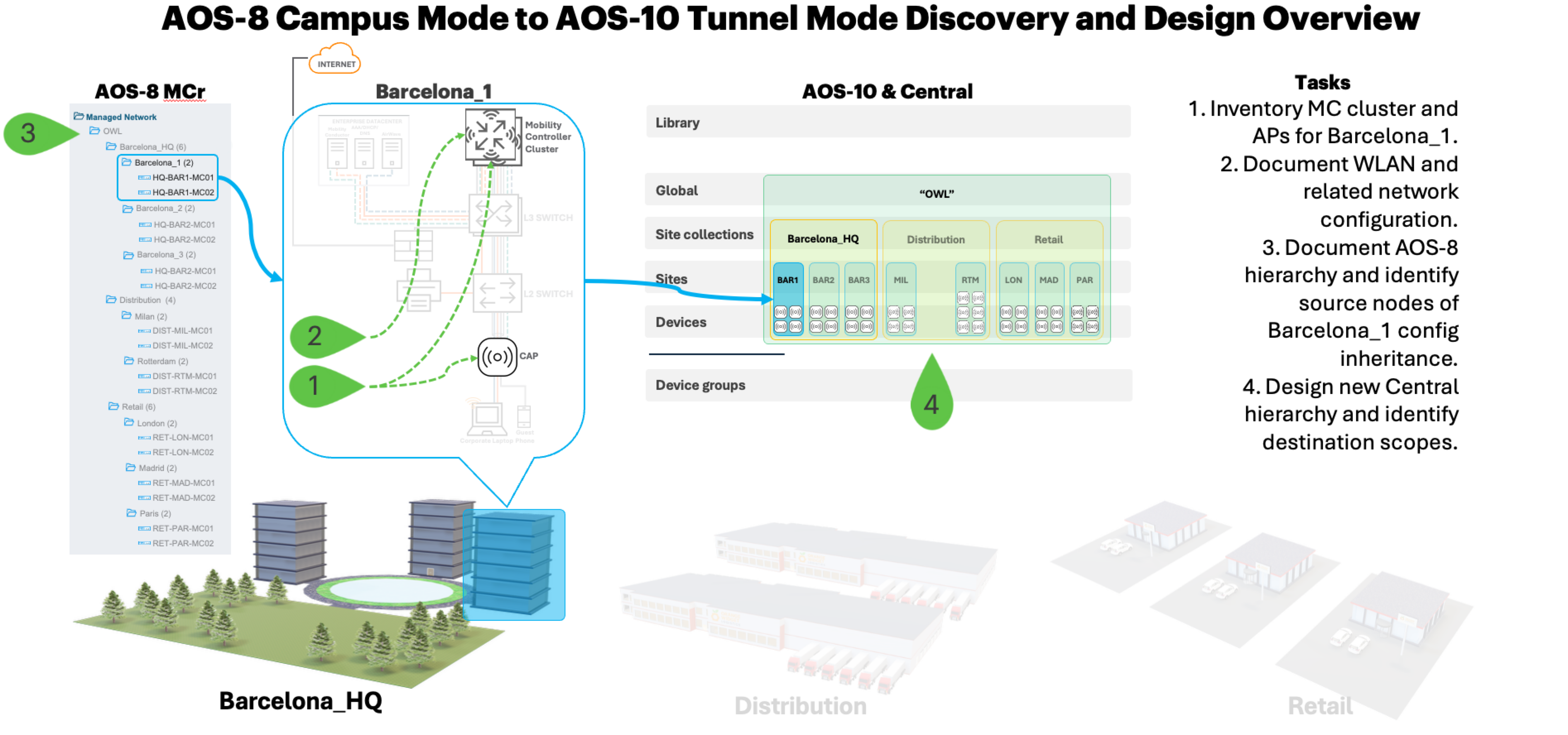
The workflow in this discovery example is organized into four high-level tasks that provide a practical framework for analyzing the existing deployment, identifying the source of configuration inheritance, and defining the equivalent scope structure in Central. Each task builds on the previous one to ensure the resulting AOS-10 implementation is predictable, aligned with operational intent, and free of unnecessary legacy configuration that commonly accumulates in WLAN environments over 5–10 years of production.
Step 1 Inventory MC cluster and APs for Barcelona_1 site
Step 2 Document WLAN and all other related network configuration
Step 3 Document the Mobility Conductor’s hierarchy and Barcelona_1 site’s Mobility Controller’s configuration inheritance source
Step 4 Translate the AOS-8 hierarchy into Central scopes
1: Inventory Mobility Controllers and APs for Site
The first task in this discovery exercise is to identify and inventory the site’s controllers and APs. The information collected here will be used during the device onboarding phase later in this project.
Step 1 Open an SSH or console session to the Mobility Conductor, enable logging, and enter the following three commands:
   (OWL_MCr01) [mynode] #no paging
   (OWL_MCr01) [mynode] #show ap database long
   (OWL_MCr01) [mynode] #show openflow-controller switches
Note: If show openflow-controller switches command on the MCr does not provide the expected controller serial number and MAC addresses, use the traditional show inventory command on each AOS-8 controller.
Step 2 Collect the following information as highlighted in the example image below.
Hostname
Serial number
Ethernet MAC

Note: While virtual AOS-8 mobility controllers (MC-VA) are used in this discovery guide, it is for example purposes only. AOS-10 mobility gateways in a real-world migration must be physical Aruba appliances.
Step 3 Document results and store the collected information in a table for use during the onboarding process later in the project.
The following is an example table of the information collected in the above image:
| Hostname | MAC Address | Serial No. |
|---|---|---|
| HQ-BAR1-AP01 | d0:d3:aa:c0:8d:a8 | VNLBK9T8PQ |
| HQ-BAR1-AP02 | d0:d3:aa:c0:8d:98 | VNLBK9T8PN |
| HQ-BAR1-AP03 | d0:d3:aa:c0:8d:a0 | VNLBK9T8PO |
| HQ-BAR1-AP04 | d0:d3:aa:c0:8d:a1 | VNLBK9T8PP |
| HQ-BAR1-MC01 | 00:0c:11:9d:9f:e6 | MCAXD9FDC |
| HQ-BAR1-MC02 | 00:0c:11:02:f3:ba | MCLD2F3B0 |
Note: Running the show ap database long and show openflow-controller switches commands on the Mobility Conductor will list all controllers and APs tunneling to the controllers it manages. To focus on a specific subset of devices, add |include <string> to display only matching rows. For example, show ap database long include BAR1 will show all rows matching the BAR1 filter.
2: Document WLAN and Other System Configuration
WLAN Configuration
One of the more efficient ways to find WLAN configurations is within the mobility controller’s show running-config output. In AOS-8, a single SSID’s behavior is determined by a chain of interconnected profiles that starts with the wlan virtual ap-profile. For accurate WLAN migration, all referenced elements must be identified, traced, and documented in the order of their nesting dependencies.
The following steps can be followed to collect the WLAN information for the example Barcelona_1 site.
Step 1 Open an SSH or console session to the Mobility Conductor, enable logging, and enter the following three commands:
   (OWL_MCr01) [mynode] #logon <controller-ip>
   (HQ-BAR1-MC01) [MDC] #no paging
   (HQ-BAR1-MC01) [MDC] #show running-config
| Repeat this step for all controllers in the upgrade project to document device-specific configuration, such as hostnames, VLAN interface IP addresses, and so on. |
Step 2 From the logged text file, search for the following keywords to find the WLAN configuration and tie the dependencies as described in the upcoming Configuration Mapping Reference section:
ap-grouprf dot11<a/b/6ghz> radio profileswlan virtual-apwlan ssid-profileaaa profileaaa authentication dot1xaaa server-groupaaa authentication-serveruser-role
Step 3 Record the results and save the gathered information in a table for reference during the Configuration and Staging phase later in the project.
Step 4 Repeat steps 2 and 3 for every production virtual AP profile to collect all WLANs.
Step 5 Repeat steps 1-4 for all Mobility Controllers in the cluster to be migrated.
Configuration Mapping Reference
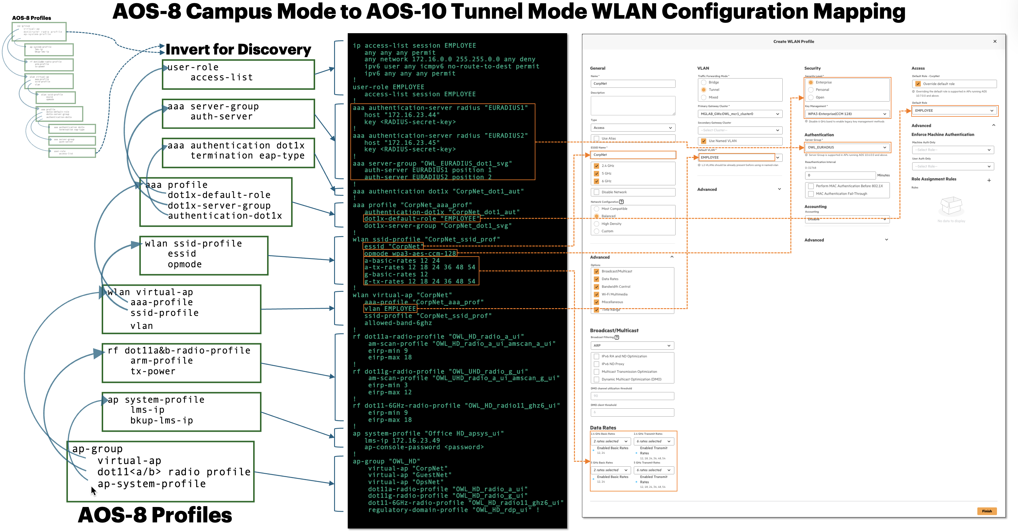
The image below demonstrates how the first WLAN (CorpNet) configuration is traced from the AOS-8 profile stack, displays the running-config output, and maps to its corresponding configuration fields in Central. On the left, it highlights the interconnected AOS-8 profiles that define the SSID behavior, while the center shows the extracted CLI configuration for CorpNet. The right side illustrates how these parameters (SSID settings, VLAN assignment, authentication method, server groups, and default role) are recreated within the Central UI.
The image below continues the same mapping guidance, but for RF configuration.
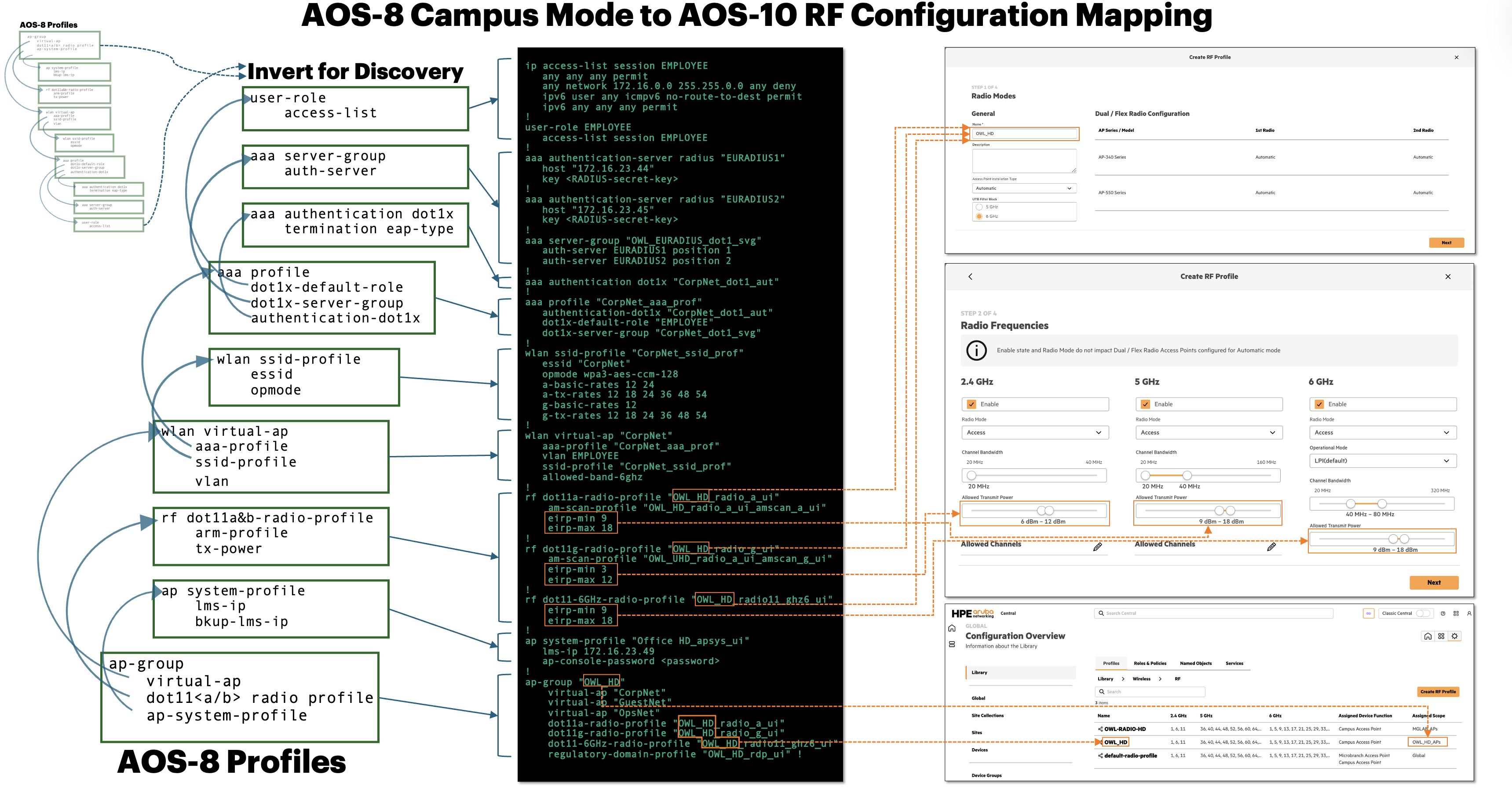
These visual mappings reinforce the discovery methodology: every setting documented in the CorpNet WLAN table must be directly traceable to a profile reference in AOS-8 before being rebuilt in Central. By validating each dependency in this way, engineers ensure functional parity between the AOS-8 deployment and the new AOS-10 configuration model.
Example CorpNet (802.1X) WLAN Discovery Results Document
The example table below organizes the discovered CorpNet WLAN settings to support communication, peer review, and SSID reconstruction in Aruba Central.
| Setting Name | Value |
|---|---|
| General Column | |
| Name (SSID) | CorpNet |
| Bands | 2.4 GHz, 5 GHz, 6 GHz |
| Legacy 2.4 GHz Transmit Rates | 12-54 |
| Legacy 5 GHz Transmit Rates | 12-54 |
| Beacon Rate | Default |
| VLANs Column | |
| Forwarding Mode | Tunnel |
| Primary Gateway Cluster | [Cluster Name] |
| VLAN ID | 2 |
| Security Column | |
| Security Level | Enterprise |
| Key Management | WPA3-Enterprise(128) |
| Primary & Secondary RADIUS Servers | 172.16.23.43, 172.16.23.44 |
| Access Column | |
| Default Role | Authenticated |
Example OpsNet (PSK) WLAN Discovery Results Document
The example table below organizes the discovered OpsNet WLAN settings to support communication, peer review, and SSID reconstruction in Aruba Central.
| Setting Name | Value |
|---|---|
| General Column | |
| Name (SSID) | OpsNet |
| Bands | 2.4 GHz, 5 GHz, 6 GHz |
| Legacy 2.4 GHz Transmit Rates | 12-54 |
| Legacy 5 GHz Transmit Rates | 12-54 |
| Beacon Rate | Default |
| VLANs Column | |
| Forwarding Mode | Tunnel |
| Primary Gateway Cluster | [Cluster Name] |
| VLAN ID | 3 |
| Security Column | |
| Security Level | Personal |
| Key Management | WPA3-Personal |
| PSK | [PSK] |
| Access Column | |
| Default Role | Authenticated |
Example GuestNet (PSK) WLAN Discovery Results Document
The example table below organizes the discovered GuestNet WLAN settings to support communication, peer review, and SSID reconstruction in Aruba Central.
Note: GuestNet will be modernized from the current PSK to Enhanced Open (OWE) with a Central NAC captive portal; the guest VLAN (100) and tunnel forwarding will be retained.
| Setting Name | Value |
|---|---|
| General Column | |
| Name (SSID) | GuestNet |
| Bands | 2.4 GHz, 5 GHz, 6 GHz |
| Legacy 2.4 GHz Transmit Rates | 12-54 |
| Legacy 5 GHz Transmit Rates | 12-54 |
| Beacon Rate | Default |
| VLANs Column | |
| Forwarding Mode | Tunnel |
| Primary Gateway Cluster | [Cluster Name] |
| VLAN ID | 100 |
| Security Column | |
| Security Level | Personal |
| Key Management | WPA3-Personal |
| PSK | [PSK] |
| Access Column | |
| Default Role | Authenticated |
General AOS-8 Campus WLAN Discovery Reference
To help apply this mapping example to other WLANs, the graphic below summarizes the method used above for systematically extracting the configuration from the show running-config output. By inverting the profile stack, the logical building sequence becomes visible, allowing engineers to identify every object required to reliably create the WLAN and RF configuration in AOS-10 with Central.

LAN and Controller System Settings Discovery
In addition to WLAN configuration, the controller’s LAN and system-level settings must be reviewed and documented. These parameters define how the controller integrates with the wired network and enterprise services. They are not rebuilt automatically during migration and must be validated to ensure operational continuity in AOS-10.
This step focuses on extracting controller-level settings that affect:
- Management reachability
- VLAN and gateway design
- Infrastructure services (NTP, DNS, SNMP)
- Authentication server connectivity
- Regulatory and RF constraints
- Administrative access
Begin by generating a full show running-config output and saving it to a text file. Rather than reading the file linearly, use targeted searches to locate each configuration block listed below. Capture the complete configuration section for each item and store it with the project documentation for staging and validation.
Note: In large configurations, it may be faster to use CLI filters such as show running-config begin <keyword> when collecting data directly from the controller.
Controller and LAN Configuration Checklist
| Information Type | Search Keyword | What to Capture |
|---|---|---|
| Hostname | hostname | System identity |
| NTP | ntp server | All defined NTP servers |
| Time Zone | clock timezone | Time zone and offset |
| DNS | ip name-server | All configured name servers |
| SNMP | snmp-server | Communities, hosts, versions |
| Management IP | controller-ip and interface vlan | VLAN ID, IP address, subnet mask |
| Default Gateway | ip default-gateway | Layer 3 upstream path |
| VRRP / VIP | vrrp | Virtual IPs and priorities |
| Admin Access | mgmt-user | Defined admin users and roles |
| Physical Ports | interface gigabitethernet | Trunk mode, native VLAN, allowed VLANs |
| AP Groups | ap-group | Radio, regulatory, and virtual-ap bindings |
| Authentication Servers | aaa authentication-server | RADIUS servers and keys |
| Country Code | country-code | Regulatory domain settings |
| Cluster Name and Members | lc-cluster group-profile& lc-cluster exclude-vlan if applicable | Controller’s cluster membership details |
| VLAN Definitions | vlan , vlan-name, and interface vlan | All VLAN IDs, names, SVI IP addresses, and any VLANs referenced by WLAN virtual-ap profiles |
Example of VLAN information:
vlan 23
vlan-name MGMT
vlan MGMT 23
!
interface vlan 23
   ip address 172.16.23.47 255.255.255.0
Site Considerations
Repeat this process for all controllers to be upgraded at the site. Pay particular attention to:
- Management VLAN differences between appliances
- VRRP or VIP assignments used for controller clustering
- Port-level trunk configurations that impact AP and client connectivity
These system-level parameters often expose hidden dependencies that must be preserved when moving to AOS-10 tunnel mode.
Example Controller and VLAN Discovery Summary
The following example illustrates how controller-level discovery results can be organized to support peer review, scope validation, and reconstruction of gateway settings in Central.
Documenting this information in a structured format enables side-by-side comparison of clustered controllers, highlights configuration differences that may affect migration, and provides a validated reference during staging and cutover.
Controller Discovery Summary - Barcelona_1 Site
| Category | Setting | Controller 1 (HQ-BAR1-MC01) | Controller 2 (HQ-BAR1-MC02) |
|---|---|---|---|
| Identity | Hostname | HQ-BAR1-MC01 | HQ-BAR1-MC02 |
| Model | 7210 | 7210 | |
| Serial Number | [Captured] | [Captured] | |
| Ethernet MAC | [Captured] | [Captured] | |
| Site | Site | Barcelona_1 | Barcelona_1 |
| Intended Central Group | Device Group | OWL_GW_BAR1 | OWL_GW_BAR1 |
| Time & Services | Time Zone | Europe/Madrid | Europe/Madrid |
| NTP Servers | 10.10.10.10, 10.10.10.11 | 10.10.10.10, 10.10.10.11 | |
| DNS Servers | 10.10.10.10, 10.10.10.11 | 10.10.10.10, 10.10.10.11 | |
| Management & L3 | Management VLAN | 23 | 23 |
| Management IP | 172.16.23.47 | 172.16.23.48 | |
| Subnet Mask | 255.255.255.0 | 255.255.255.0 | |
| VRRP VIP | 172.16.23.49 | 172.16.23.49 | |
| Default Gateway | 172.16.23.1 | 172.16.23.1 | |
| WLAN Dependencies | SSIDs | CorpNet, OpsNet, GuestNet | CorpNet, OpsNet, GuestNet |
| AP Groups | OWL_HD, OWL_UHD, OWL_Outdoor | OWL_HD, OWL_UHD, OWL_Outdoor | |
| RADIUS Servers | 172.16.23.43, 172.16.23.44 | 172.16.23.43, 172.16.23.44 | |
| RADIUS Secret | Captured separately | Captured separately |
VLAN Definitions Summary
All VLAN IDs and associated names used by the controller, WLANs, and upstream network must be documented. This ensures accurate VLAN recreation, correct tunnel forwarding behavior, and alignment with gateway cluster design in Central.
| VLAN Name | VLAN ID |
|---|---|
| MGMT | 23 |
| EMPLOYEE | 2 |
| EMPLOYEE_OPS | 3 |
| GUEST | 100 |
| IOT | 192 |
With controller-level and VLAN dependencies documented, the next step is to determine where each configuration element is committed within the AOS-8 hierarchy. Understanding commit locations and inheritance boundaries ensures that the scope is correctly replicated or intentionally redesigned when building the equivalent structure in Central.
3: Document Mobility Conductor Hierarchy
The AOS-8 Mobility Conductor provides visibility into configuration hierarchy and inheritance. Understanding where configuration is committed today is critical to accurately replicating or redesigning the hierarchy within Central.
Commands
The following CLI commands generate a text-based view of the current AOS-8 hierarchy. The output lists each node along with its full path, allowing engineers to trace configuration scope and inheritance boundaries.
(OWL_MCr01) [mynode] #no paging
(OWL_MCr01) [mynode] #show configuration node-hierarchy
The illustration below correlates the CLI output with the AOS-8 Mobility Conductor UI and the anticipated AOS-10 Central scope structure. Key nodes and target scopes are highlighted to demonstrate how existing hierarchy levels map to Central constructs. The connecting lines emphasize direct relationships between AOS-8 configuration nodes and their proposed AOS-10 destination scopes.

The result is the Central hierarchy definition listed as required output of the Discovery → Staging Contract.
Configuration Commit Locations
Purpose
After documenting the controller and hierarchy structure, the next step is to determine where each configuration element is committed within the AOS-8 hierarchy. Accurately identifying inheritance sources ensures configuration is created at the correct level in Central.
Method
The following command displays the effective configuration for a node and identifies the original commit location of each configuration line.
(OWL_MCr01) [mynode] #show configuration effective detail <node-path | name>
This output provides:
- The full effective configuration applied to the node
- The source node where each setting was originally committed
- Visibility into inherited versus locally defined configuration
This is the most efficient way to trace configuration inheritance and identify override points.
Practical Use Cases
Typical questions answered during discovery include:
- Was this VLAN configured locally on the controller or inherited from a parent node?
- At which level was a PSK overridden for a global SSID?
- Is this AAA profile defined at the site level or globally?
Example Output Interpretation
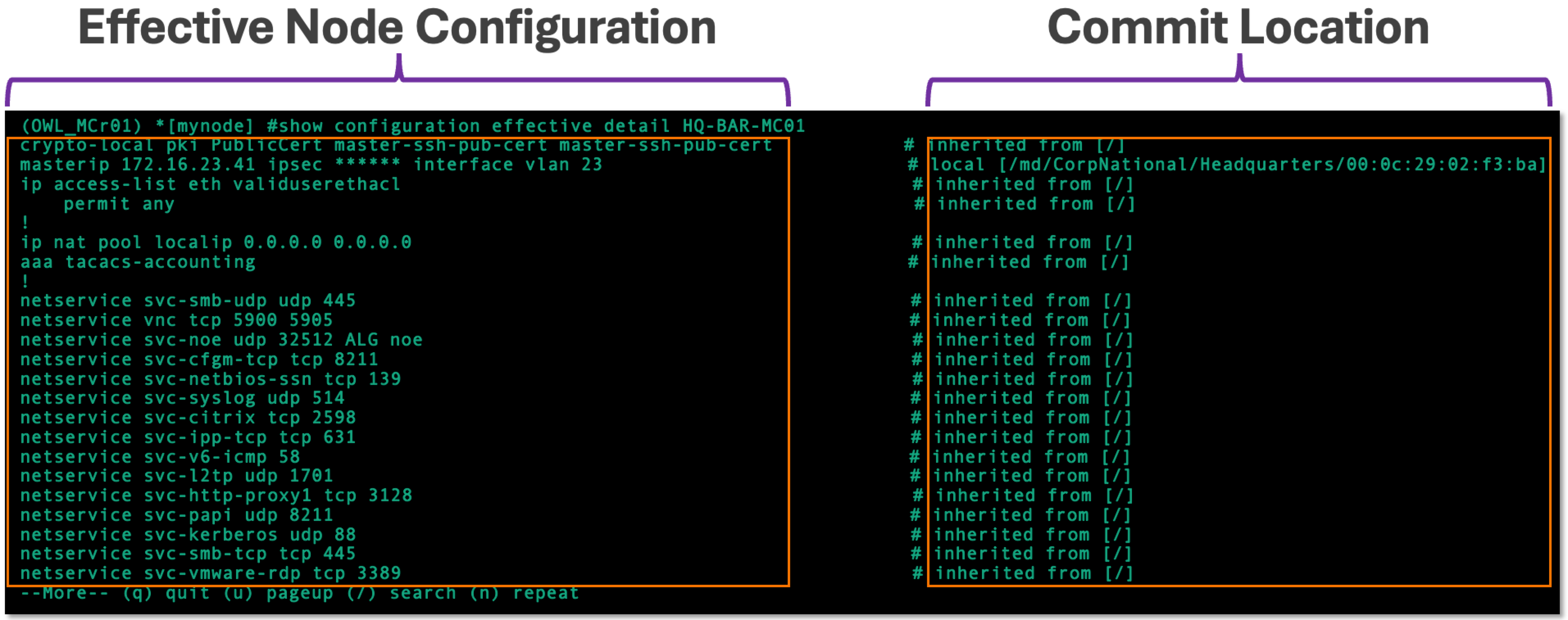
The examples below illustrate:
- The effective configuration for the selected controller
- The corresponding commit location for each configuration line
Inherited settings are clearly identified, allowing engineers to determine whether configuration must be recreated at a Global, Site Collection, Site, or Device Group level in Central.
Note: To view encrypted configuration elements such as RADIUS secrets or passphrases in plain text, run the encrypt disable command prior to executing the show configuration effective detail command.
Command Execution Context
If issued from the [mynode] level, as shown in the image above, the target node must be specified explicitly. However, when the CLI session is already positioned at the target node, the command may be executed without a path, as shown in the image below. The output remains the same and confirms both the effective configuration and the commit location for each inherited or locally defined setting.

Engineers can copy any node path obtained from the show configuration node-hierarchy command collected earlier and use it directly with the show configuration effective detail command to analyze inheritance at any level of the hierarchy.
Analyzing Commit Locations at Scale
The show configuration effective detail command provides precise commit location information, but large outputs can be difficult to analyze manually.
By leveraging the delimiter character (#) between the configuration line and its commit source, engineers can quickly isolate inherited versus locally defined configuration using a spreadsheet application such as Excel or Google Sheets.
This method enables rapid filtering of configuration by commit location, making it significantly easier to validate scope boundaries before rebuilding the hierarchy in Central.
Using Excel
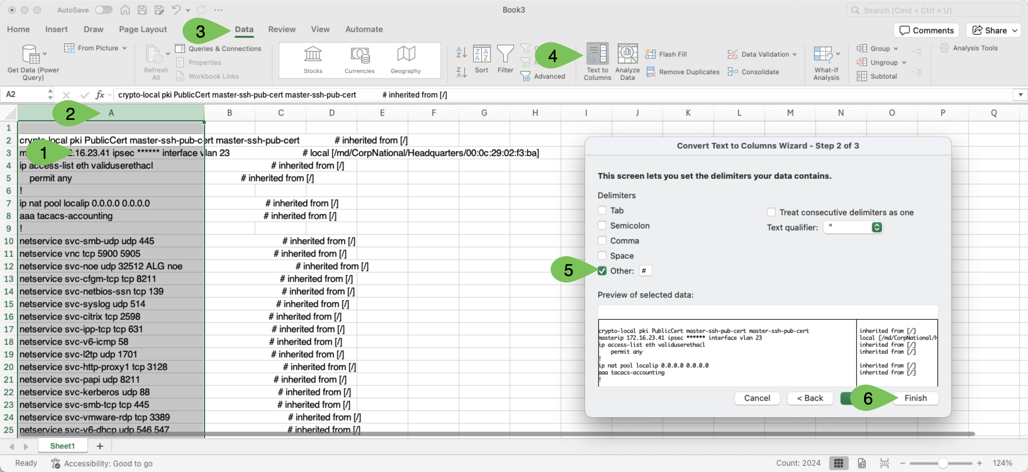
Follow the steps below to process output with Excel:
Step 1 Copy the full output of the show configuration effective detail <node> command and paste it into the first column.
Step 2 Highlight the full column
Step 3 Click Data
Step 4 Click the Text to Columns button
Step 5 Check the box next to the Other option and enter “#” as the delimiter
Step 6 Click Finish
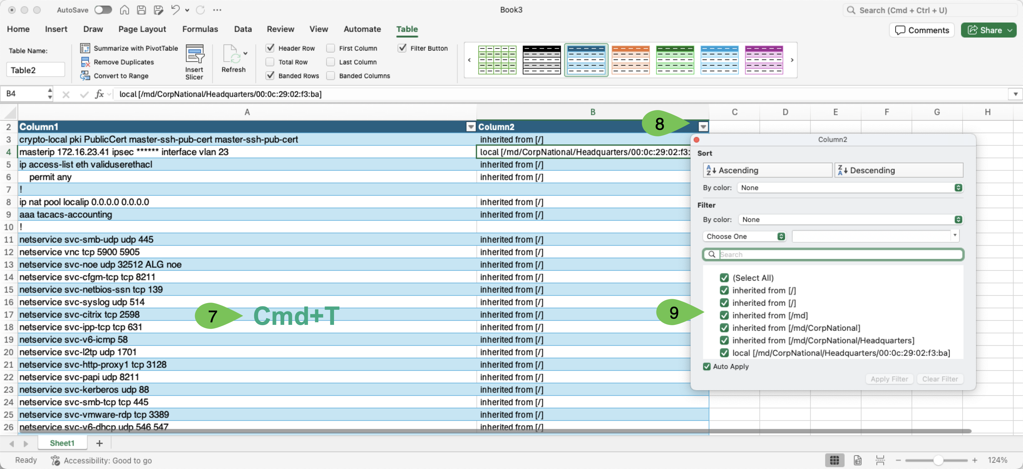
Step 7 With one of the populated cells selected, type Cmd+T to convert the content into a table.
Step 8 Click the dropdown arrow at the top of the second column
Step 9 Select one node at a time to view the configuration applied at that node
Using Sheets
Follow the steps below to process the output with Sheets:
Step 1 Copy the full output of the show configuration effective detail <node> command described above and paste it into the first column.
Step 2 Highlight the full column
Step 3 Click Data
Step 4 Click Split text to columns from the dropdown menu
Step 5 Find the Separator window and click the Detect Automatically option
Step 6 Click Custom
Step 7 Type “#” as the delimiter

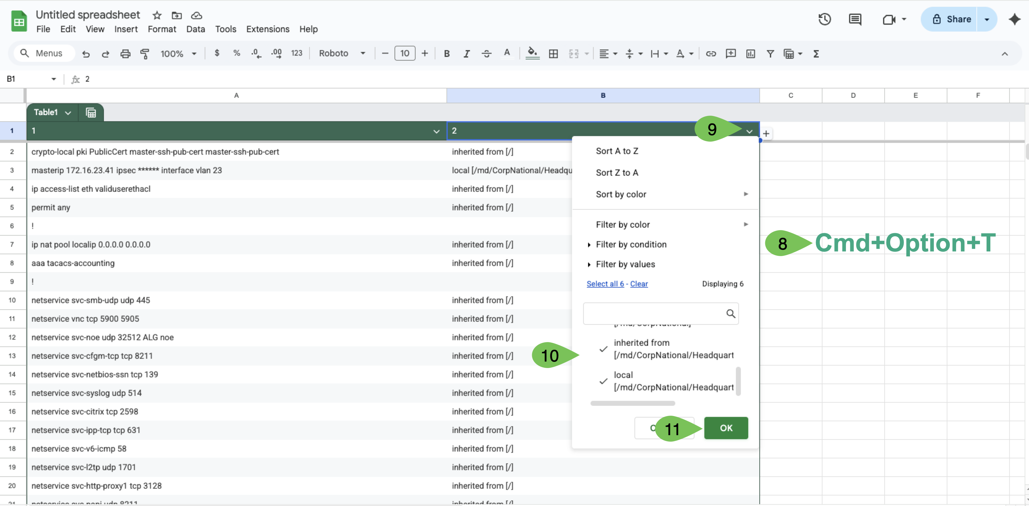
Step 8 With one of the populated cells selected, type Cmd+Option+T to convert the content into a table
Step 9 Click the dropdown arrow on the second column
Step 10 Select one node at a time to view the configuration applied at that node
Step 11 Click Ok to view
Using commit location data in this structured format allows engineers to confidently model the new Central hierarchy and assign configuration to the appropriate destination scopes, avoiding misaligned or flattened designs.
4: Translate the AOS-8 Hierarchy into Central Scopes
Using the inventory, inheritance sources, and commit locations gathered in Tasks 1-3, translate the existing AOS-8 configuration hierarchy into the target Central scope structure. The goal of this task is not to build anything in Central yet, but to produce a Central hierarchy definition - the mapping that the Configuration and Staging phase uses to create the scopes.
Central organizes configuration into nested scopes - Global → Site Collection → Site →Device and Device Group →Device - with reusable profiles held in the Library. Configuration applied at a higher scope is inherited by everything beneath it. Translating the hierarchy is a matter of deciding which AOS-8 node maps to which Central scope.
The following steps will translate this reference customer’s hierarchy. Some steps will vary depending on the number of levels in the AOS-8 environment.
Step 1 Start from the node hierarchy. Using the show configuration node-hierarchy output collected in Task 3, list each AOS-8 configuration node and its level in the tree.
Step 2 Map each node level to its Central scope equivalent. In the OWL example:
The customer root node (
OWL) represents the tenant itself and is managed at Global scope.
First-level groups that represent a region or business function (
Barcelona_HQ,Distribution,Retail) map to Site Collections.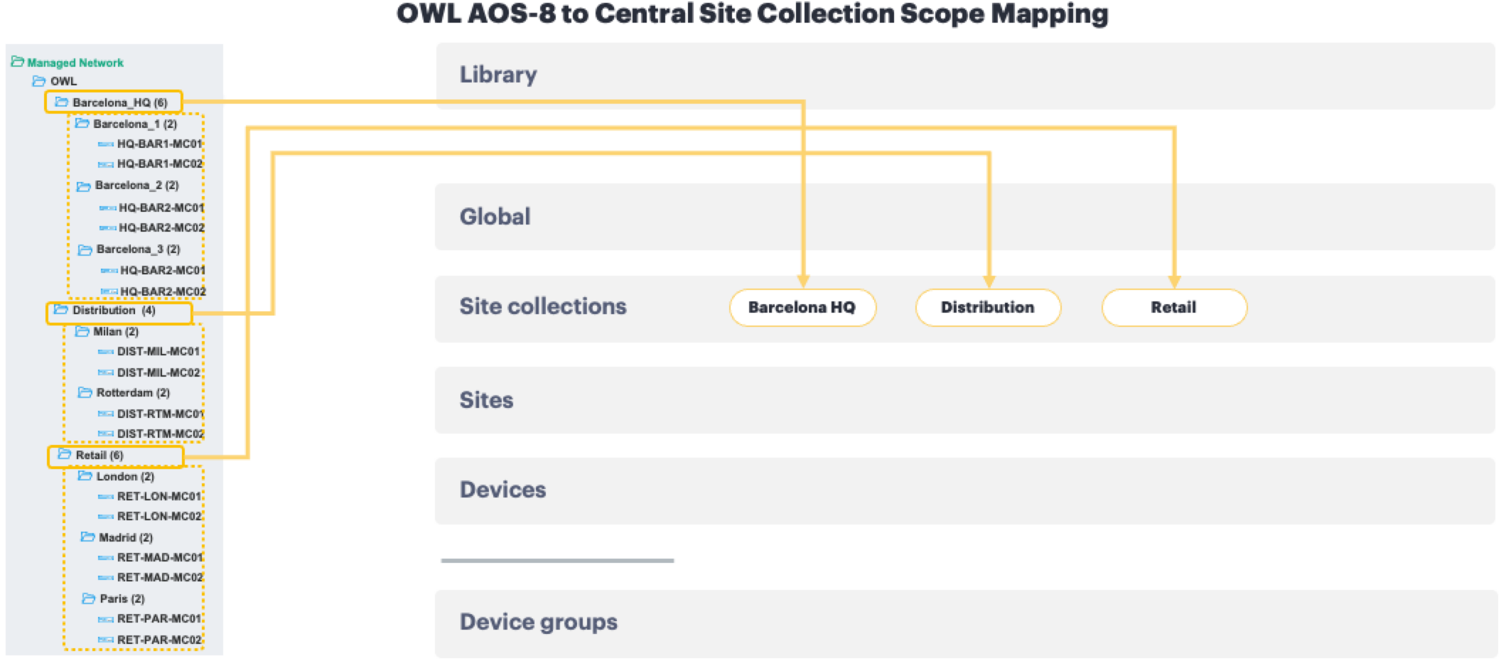
Second-level groups that represent an individual building or branch office (
Barcelona_1,Milan,London, and so on) map to Sites.
The controllers and APs beneath each location (not illustrated here) become Devices, assigned to sites and organized into Device Groups by function. (Device onboarding and placement are performed in a later phase.)
Step 3 Define Sites. Create one Site for each physical location that corresponds to a site-level node in the AOS-8 hierarchy. Sites also anchor per-site services and physical location (address / GPS), which Central can use to set country code and time zone automatically. 
Step 4 Define Site Collections. Group related sites that should share inherited configuration into a Site Collection. Create only the collections the design requires - overuse introduces unnecessary inheritance complexity.

Step 5 Define Device Groups. In Central, both gateways and access points are organized into device groups - a configuration scope shared by a set of like devices. The two map from AOS-8 differently, so handle them separately. Access points are grouped campus-wide in the Barcelona HQ example (one device group per AP role, spanning every site), while gateways are grouped per building, because a gateway cluster can only form among gateways in the same device group.
- Access points map directly. For OWL, each AOS-8 AP group becomes one Central AP device group. These are
OWL_HD_APs,OWL_UHD_APs, andOWL_OUTDOOR_APs- one per AP group documented in Task 2, named without a building suffix because each spans every site. The RF and WLAN behavior each AP group defined is recreated through RF, AP System, and WLAN profiles applied at the device-group scopes. - Gateways map by cluster. AOS-8 has no AP group equivalent for controllers; they live in the Mobility Conductor’s configuration node hierarchy (folders in the conductor UI) and are clustered using
lc-clusterprofiles. In Central, a gateway cluster forms only among the gateways in a single device group, so the unit that translates cleanly is the cluster - each AOS-8 gateway cluster becomes one gateway device group. Barcelona_1’s two-controller cluster becomesOWL_GW_BAR1, and the pattern repeats per building. Map by cluster rather than by folder: for some customers, a single AOS-8 node can contain more than one cluster, and each of those clusters would become its own gateway device group.
All device groups are created in classic Central with the Allow New Central to overwrite all configurations for this group option enabled so that new Central becomes the source of truth; that creation is performed in the Staging phase.
| The illustration below demonstrates a different, but equally valid, way to create device groups in a per-building manner if buildings have specific configuration requirements. |
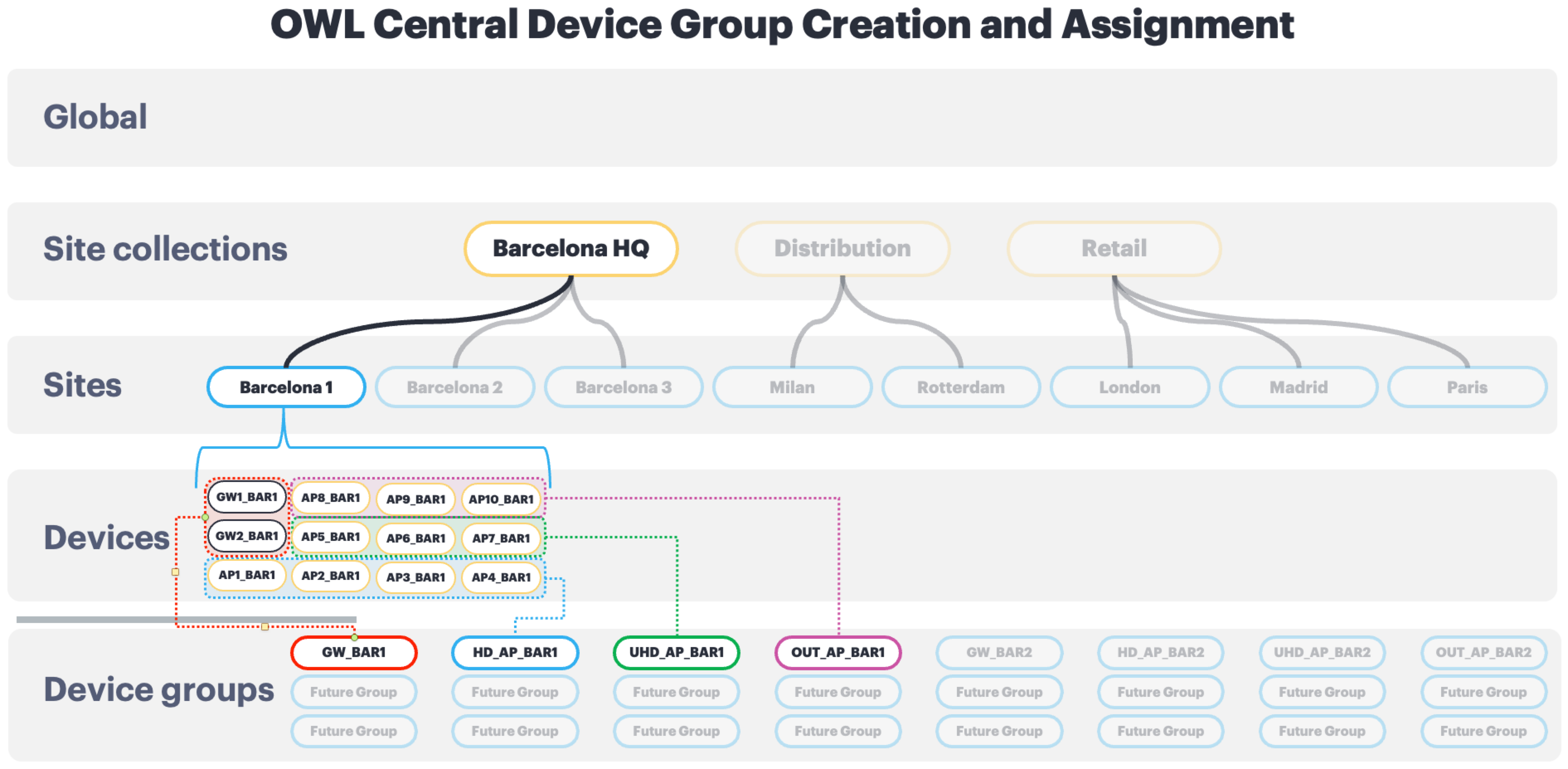
Step 6 Assign each configuration element to a commit scope. Using the commit-location analysis from Task 3, decide where each setting will live - Library, Site Collection, Site, Device Group, or Device - so that configuration is created at the correct level rather than duplicated or flattened.
| This step requires a deep understanding of AOS-8 hierarchy and inheritance, Central scope inheritance and precedence, and how configuration overrides affect network devices on the two platforms. More information can be found in the Scopes and Understanding Inheritance sections of the Configuration Model chapter in the VSG. |
Step 7 Record the result as the Central hierarchy definition. Capture the mapping in a table (below) and carry it forward as an authoritative input to Configuration and Staging.
AOS-8 Node to Central Scope Mapping
| AOS-8 Node | Central Scope | Scope Type | Parent Scope |
|---|---|---|---|
| OWL | Global | Tenant root | - |
| Barcelona_HQ | Barcelona_HQ | Site Collection | Global |
| Distribution | Distribution | Site Collection | Global |
| Retail | Retail | Site Collection | Global |
| Barcelona_1 | Barcelona_1 | Site | Barcelona_HQ |
| Barcelona_2 | Barcelona_2 | Site | Barcelona_HQ |
| Barcelona_3 | Barcelona_3 | Site | Barcelona_HQ |
| Milan | Milan | Site | Distribution |
| Rotterdam | Rotterdam | Site | Distribution |
| London | London | Site | Retail |
| Madrid | Madrid | Site | Retail |
| Paris | Paris | Site | Retail |
AOS-8 AP-Group to Central AP Device Group Mapping (Barcelona_1)
In AOS-8, an AP-group bundles the profiles that define AP behavior. In Central, each AP-group maps directly to one AP device group; the behavior is recreated through RF, AP System, and WLAN profiles. These AP device groups span every site in the campus.
| AOS-8 AP-Group | Central AP Device Group | Purpose |
|---|---|---|
| OWL_HD | OWL_HD_APs | High-density indoor APs |
| OWL_UHD | OWL_UHD_APs | Ultra-high-density indoor APs |
| OWL_Outdoor | OWL_OUTDOOR_APs | Outdoor APs |
Gateway Device Group (Barcelona_1)
| Building (Site) | Gateways | Gateway Device Group |
|---|---|---|
| Barcelona_1 | HQ-BAR1-GW01 / HQ-BAR1-GW02 | OWL_GW_BAR1 |
The illustration below repeats the diagram from the start of Task 3 (the show configuration node-hierarchy output), with connecting lines showing the direct relationship between AOS-8 configuration nodes and their proposed AOS-10 destination scopes.
The scopes documented above will be created in the Configuration and Staging phase; device onboarding and Site/Device Group assignment of production devices occur during Migration Execution.
Reference Table of Information Collection Commands
| Information Needed | Command | Where | Purpose |
|---|---|---|---|
| Configuration Node Hierarchy | #show configuration node-hierarchy | Mobility Conductor | Plan AOS 10 Site and Group structure |
| Configuration Nodes and Commit Details | #show configuration effective detail [node] #show configuration committed [node] | Mobility Conductor | Map configuration application points in AOS 10 |
| AP Inventory (Model, MAC, Serial) | #show ap database long | Mobility Conductor | Record AP details for onboarding and validation |
| AP Group Information | #show ap-group | Mobility Controller | View all AP groups |
| WLAN-related Configuration | #show ap-group [group name] | Mobility Controller | View VAP, 802.11 radio, and other AP group-related profiles |
| Associated Clients | #show ap association | Mobility Controller | List associated clients |
| Authenticated Users | #show user-table | Mobility Controller | List authenticated users |
| APs’ LLDP Neighbors | #show ap lldp neighbors | Mobility Controller | Record switch and port connections for APs |
| Active ESSIDs | #show ap essid | Mobility Controller | View active SSIDs and the number of APs per SSID |
| Active APs and Radio Stats | #show ap active | Mobility Controller | List all active APs and their radio statistics |
| Full Running Config | #show run | Mobility Controller | Collect data to reference, validate, and obtain context |
Additional Helpful CLI Commands
| Information Needed | Command | Where | Purpose |
|---|---|---|---|
| Active Ports | show port status | Mobility Controller | Identify active ports |
| VLAN Port Assignments | show trunk | Mobility Controller | To know what VLANs exist where |
| Controller/Gateway IP Address | show controller-ip | Mobility Controller | Display the controller’s assigned management IP and VLAN ID |
| Configured Local Users | show local-user db | Mobility Controller | Determine if local users exist and need to be supported in AOS 10 |
| S/N & MAC Address | show inventory | Mobility Controller | Display serial number and MAC address of the controller |
Execute the commands above on the active mobility conductor and on both AOS 8 controllers that are being upgraded to AOS 10 gateways.
AirWave Information Gathering
In addition to mobility controller information gathering, AirWave provides an alternative way to view and validate:
- Group and Site structure
- AP inventory, including associated SSIDs and configuration details.
Note: AirWave may overlap with some of the data collection points above, serving as a helpful cross-check during the migration process.
Implementation Engineer Notes
- Efficiency Tip: Use AirWave to consolidate some of the data above.
- Cross-Validation: After collecting the data, compare outputs from AirWave and CLI commands to ensure consistency.
- Backup: Save all collected outputs in a structured format (e.g., spreadsheets) for reference during and after the upgrade.
Switchport Configuration Verification
When transitioning to an AOS 10 Tunneled AP deployment, the configuration of AP switchports depends on the WLAN deployment mode. Switchport configuration examples based on the WLAN forwarding mode are provided below.
Tunnel Mode Only WLANs
- Description: All WLANs are configured in Tunnel Mode, where client traffic is tunneled back to the Mobility Gateway.
- Port Configuration: AP switchports can be configured as access ports since no VLAN tagging is required for wireless client traffic.
- Alternative Option: APs will still establish tunnels to their gateways if connected to switchports configured as trunk ports, but the native VLAN must match the access VLAN configuration to ensure that AP management traffic is handled properly (similar to AOS 6 or 8 campus mode deployments).
Configuration Example (Access Port):
interface 1/1/1
  no shutdown
  description ACCESS_PORT
  no routing
  vlan access 23
Bridge Mode WLANs
- Description: In this situation, one or more WLANs operate in Bridge Mode, where client traffic is bridged locally onto the VLANs tagged on the AP switchport.
- Port Configuration:
- AP switchports must be configured as trunk ports to allow bridged wireless traffic to access specific data VLANs.
Configuration Example (Trunk Port):
interface 1/1/2
  no shutdown
  description TRUNK_PORT
  no routing
  vlan trunk native 23
  vlan trunk allowed 1-3,23,100,192
Mixed Mode WLANs
- Description: Use a trunk port configuration to support Mixed Mode WLANs, ensuring the native VLAN is set properly and allowed VLANs are pruned as required.
- Port Configuration:
- Native VLAN for AP management traffic.
- Tagged VLANs for bridged wireless traffic in Mixed Mode WLANs.
- Prune all VLANs used for tunneled WLAN clients.
Configuration Example (Trunk Port):
interface 1/1/2
  no shutdown
  description TRUNK_PORT
  no routing
  vlan trunk native 23
  vlan trunk allowed 1-3,5-6
Checklist for Switchport Recommendations
| Forwarding Mode | Port Type | Key Configuration |
|---|---|---|
| Tunnel Mode Only | Access | - Access VLAN for AP management traffic. |
| Bridge mode | Trunk | - Include native VLAN for management. - Allow tagged VLANs for bridged traffic. |
| Mixed Mode WLANs | Trunk | - Prune tunneled VLANs. - Allow only required bridged VLANs. |
Switchport Tips for Implementation
- Access Port Simplicity in Tunnel Mode: Using access ports in a Tunnel Mode Only deployment simplifies configuration and eliminates the need to manage trunk VLANs.
- VLAN Management in Mixed Mode: Be diligent about pruning VLANs for tunneled traffic in Mixed Mode WLANs to avoid misconfigurations that could lead to broadcast storms or unexpected traffic flows.
- Documentation: Keep a clear record of VLAN assignments for each port, especially in environments where both Tunnel Mode and Mixed Mode WLANs coexist.
- Validation: After configuring switchports, validate AP connectivity and client traffic flows to ensure that management, tunneled, and bridged traffic is properly routed.
By following these guidelines and examples, implementation engineers can confidently configure AP switchports to support the requirements of AOS 10 deployments while minimizing misconfiguration risks and ensuring efficient traffic management.
Discovery Outputs Required for Aruba Central Staging
The purpose of the Discovery phase is to produce a defined set of design artifacts that are consumed directly by the Configuration and Staging phase. Staging activities in HPE Aruba Networking Central assume that these outputs are complete, accurate, and validated.
The following discovery outputs form the Discovery → Staging Contract:
- Central hierarchy definition Sites, groups, and any labeling strategy derived from the AOS-8 configuration hierarchy.
- Gateway and AP inventory Device models, serial numbers, MAC addresses, management IPs, and site/group assignments required for onboarding and clustering.
- VLAN catalog Named VLANs, VLAN IDs, and their usage across gateways and WLANs.
- WLAN catalog SSIDs with security mode, bands, forwarding mode (tunnel, bridge, or mixed), and VLAN associations.
- Authentication and AAA catalog RADIUS servers, shared secrets, ports, and RFC3576 (CoA) requirements.
- Role and policy mapping (out of scope in this release of the guide) User roles, policy rules, and any required network destinations or policy ordering constraints.
These artifacts are used to create Central objects at the appropriate scope (Library, Site, Site Collection, Group, or Device) without requiring additional access to the production AOS-8 environment.
Note: In the OWL reference deployment, all discovery outputs are consolidated into structured tables and catalogs before any Aruba Central configuration is created. This allows staging to proceed independently and prevents repeated access to the production AOS-8 controllers during migration execution.
Exit Criteria for Discovery
The Discovery phase is complete when the following conditions are met:
- All Discovery → Staging contract artifacts are collected, reviewed, and validated.
- The Aruba Central site and group hierarchy is finalized.
- WLAN forwarding mode decisions (tunnel, bridge, or mixed) are documented.
- Migration sequencing, validation checkpoints, and rollback assumptions are defined.
Once these criteria are satisfied, proceed to Configuration and Staging, where the discovery artifacts are instantiated as Aruba Central configuration objects.